manuals.online logo
Brands
  1. Home
  2. •
  3. Brands
  4. •
  5. Nibe
  6. •
  7. Heat Pump
  8. •
  9. Nibe F2040 Series User manual

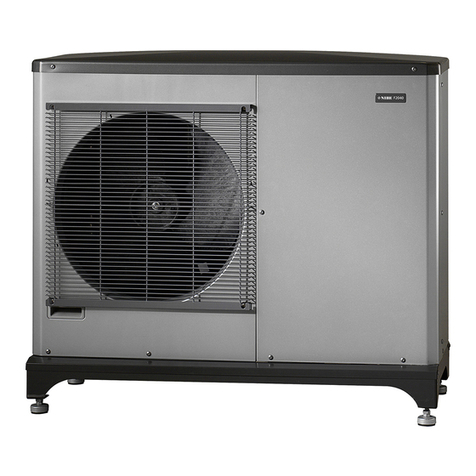
Nibe F2040 Series User manual

INSTALLATION GUIDE + PRE-COMMISSIONING CHECKLIST
F2040 6/8/12KW + VVM320
NB. This reference guide is supplementary to the NIBE installation manual and is not intended to replace it.
Page | 2
Positioning of F2040 (outdoor unit)
➢Position the F2040 as close as practically possible to the VVM320, a Maximum of ten metres between units is recom-
mended to minimize heat loss and reduce running costs.
➢Install on a solid Base or wall bracket (second story height not recommended).
➢Leave space around unit for to ensure good air circulation. (Distances specified are minimum not a target)
➢Avoid installation adjacent to sensitive areas e.g. bedrooms; noise levels are lower than most oil or gas boilers.
➢300mm clearance below unit is specified by NIBE due to frequent snowfalls in Sweden. UNIPIPE Ireland leave the
minimum clearance to the discretion of the plumber, however, if left below 300mm and snow damage is encountered,
UNIPIPE will not accept responsibility for any damage incurred.
Page | 3
Positioning of VVM320 (indoor unit)
➢Leave sufficient space in front of the unit for servicing as per the manual.
➢Leave minimum 25mm behind unit for pipes/cables.
➢Use adjustable feet to level the unit.
➢Leave access to filters/valves for servicing.
Page | 4
Mechanical Connection of F2040
➢Connect to the unit using the supplied flexible hoses with minimum use of elbows.
➢The Flexible hose incorporating a Manual air vent must be on the flow pipe (top connection).
➢Flexis/pipework must be insulated and weatherproofed with a UV stable product.
➢Exposed pipework must be kept to a minimum.
➢Pipework routed below ground must be low heat loss and kept to the minimum possible length.
➢Condensation will be produced by and drip from below the unit. This must be safely routed to a drain/soakaway,
avoiding ingress on walkways.
Page | 5
Mechanical Connection of VVM320
Pipe connections (22mm) Strainer Valve
Tundish at rear of unit Secondary return connection inside unit (15mm)
Page | 6
Mechanical Connection of VVM320
➢Pipework Between the F2040 and VVM 320 must be sized by the installer. Minimum 32mm multilayer pipe or one-inch
copper recommended.
➢Other Pipework To/From VVM320 must be sized by the installer and equivalent to the connections at a minimum.
➢All High points on the heating side should incorporate venting facilities. (Flamco auto air vents recommended)
➢Elbows should only be used when necessary,90 Degree pull bends are recommended.
➢Pipe runs should be designed to consist of minimum bends and fittings reducing pressure/flow losses.
➢Pipes should be installed and bracketed neatly for aesthetic purposes.
➢The strainer valve supplied should be installed on the return pipe to the F2040 to protect the internal heat exchanger.
The direction of flow is indicated on the valve body and must be adhered to. It should be installed to allow easy re-
moval of the centre nut for cleaning purposes. This should be cleaned after the initial operation.
➢The Tundish may release water under certain conditions and must be piped to a drain or soakaway. A resealable trap is
recommended to prevent sewer smells if applicable.
➢A filling valve and pressure gauge is incorporated within the unit and is not required externally.
➢A ten-litre heating expansion vessel is incorporated within the unit and should be pre-set to the required (cold fill)
pressure.
➢An additional heating expansion vessel should be fitted if required relative to the system volume.
➢A potable expansion vessel must be fitted on the hot pipe leaving the VVM320 (non-return valve on cold inlet)
➢If connecting to an existing heating system, the system must be flushed and cleansed prior to interconnection.
Page | 7
Page | 8
Electrical Connection of F2040
F2040 Communication board (AA23)
➢The mains cable is pre-wired in the unit and must be terminated in a local rotary isolator. (not a cooker switch)
➢The rotary isolator must be supplied by 6 or 10 Square cable back to the Fuse board. (dependent on distance and
sized by the electrician)
➢The circuit breaker must be 25 Amp “motor” rated.
➢The communication (comms) cable must be screened cat5 or equivalent. It must also be separated from power supply
runs and the foil screen grounded on one end only.
Page | 9
Electrical Connection of VVM320
VVM320 Communication board (AA3) Additional relay
Page | 10
Electrical Connection of VVM320
➢The mains cable is pre-wired in the unit and must be terminated in a local rotary isolator.
➢The rotary isolator must be supplied by 6 or 10 Square cable back to the fuse board. (dependant on distance and sized by
the electrician)
➢The circuit breaker must be rated for 32 Amps.
➢The communication (comms) cable must be screened cat5 or equivalent. It must also be grounded in the outdoor unit
only.
➢All sensor cables must be screened cat5 or equivalent.
➢The additional relay is a volt free contact used to power the external pump. The power supply for the pump is sourced
externally with the live cable routed through the additional relay (X7) allowing control by the VVM320.
➢The outdoor sensor must be positioned on a north/ north west facing surface to avoid direct sunlight interference. Ideally
located under a soffit for water protection. Kept at a serviceable height if possible.
➢Install the indoor sensor in a central position. A suitable location is on a free inner wall in a hall approx. 1.5 m above the
floor. If the room sensor is used in a room with underfloor heating, it should only have an indicatory function, not control
of the room temperature.
Page | 11
Filling and venting the system
Buffer vent
➢Fill the central heating side though the filling loop in the VVM320
➢Vent the hot water coil via the coil vent
➢Vent the buffer via the buffer vent
➢Vent all high points on pipework
➢Pressurise the system to the required cold fill pressure (typically 1-1.5 bar).
➢The hot water cylinder must be filled prior to turn on.
➢The cylinder is filled via the cold-water supply as any standard cylinder.
➢Ensure under floor heating/radiators are filled and vented correctly.
➢There should be no gurgling sounds from the system.
Coil vent
NB. The Outdoor Unit Must be powered up a minimum of 6 hours before the indoor unit.
Page | 12
NIBE uplink
➢Connect the VVM to the router with Cat5e UTP
straight with male to male RJ45 connectors.
➢A planet earth symbol will appear on the main
menu screen if the connection is ok.
➢Follow the connection instructions on
www.nibeuplink.com

Other manuals for F2040 Series

6

This manual suits for next models

1

Other Nibe Heat Pump manuals

Nibe F1255PC BE User manual

Nibe

Nibe F1255PC BE User manual

Nibe FIGHTER 600P User manual

Nibe

Nibe FIGHTER 600P User manual

Nibe F125 User guide

Nibe

Nibe F125 User guide

Nibe MT-WH 2029-F User manual

Nibe

Nibe MT-WH 2029-F User manual

Nibe S1155 User manual

Nibe

Nibe S1155 User manual

Nibe DRAZICE TJ 2 EHP 6 kW Specification sheet

Nibe

Nibe DRAZICE TJ 2 EHP 6 kW Specification sheet

Nibe F750 User guide

Nibe

Nibe F750 User guide

Nibe F1155 Series User manual

Nibe

Nibe F1155 Series User manual

Nibe F470 User guide

Nibe

Nibe F470 User guide

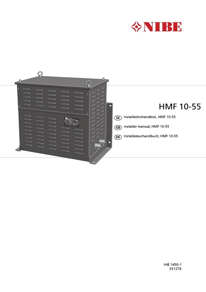
Nibe HMF 10-55 User guide

Nibe

Nibe HMF 10-55 User guide

Nibe FIGHTER 310P Technical specifications

Nibe

Nibe FIGHTER 310P Technical specifications

Nibe CLIMATEMASTER Tranquility TES Guide

Nibe

Nibe CLIMATEMASTER Tranquility TES Guide

Nibe PCM S40 User guide

Nibe

Nibe PCM S40 User guide

Nibe F750 Operating instructions

Nibe

Nibe F750 Operating instructions

Nibe S1156 User guide

Nibe

Nibe S1156 User guide

Nibe F470 User guide

Nibe

Nibe F470 User guide

Nibe FIGHTER 120 User manual

Nibe

Nibe FIGHTER 120 User manual

Nibe F750f750 User manual

Nibe

Nibe F750f750 User manual

Nibe SMO 20 User manual

Nibe

Nibe SMO 20 User manual

Nibe F130 User manual

Nibe

Nibe F130 User manual

Nibe F2026 User guide

Nibe

Nibe F2026 User guide

Nibe F2050 User manual

Nibe

Nibe F2050 User manual

Nibe Fighter 200P User manual

Nibe

Nibe Fighter 200P User manual

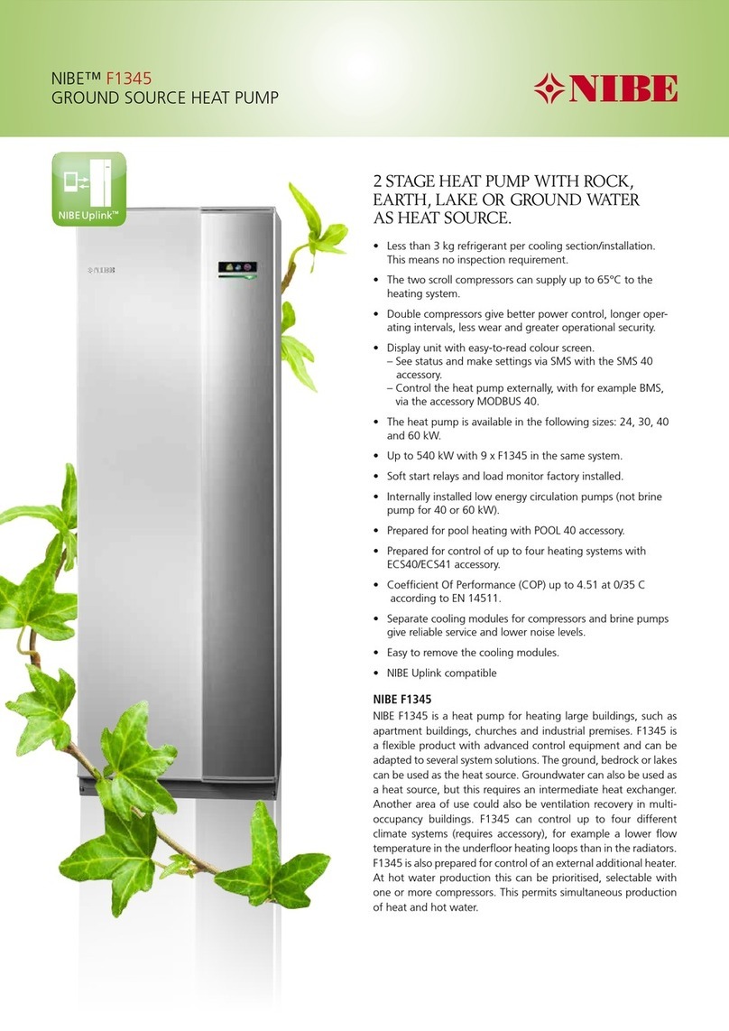
Nibe F1345 Series User manual

Nibe

Nibe F1345 Series User manual
Popular Heat Pump manuals by other brands

Smith AH - 290 Installation, user and service manual

Smith

Smith AH - 290 Installation, user and service manual

GE AZ58H12EADM1 and Owner's manual and installation instructions

GE

GE AZ58H12EADM1 and Owner's manual and installation instructions

AquaViva SUPERIOR AVSP-FI9RW installation manual

AquaViva

AquaViva SUPERIOR AVSP-FI9RW installation manual

Bosch IDP Technical service bulletin

Bosch

Bosch IDP Technical service bulletin

Daikin Altherma 3 H HT Series installation manual

Daikin

Daikin Altherma 3 H HT Series installation manual

Haier MRV II AV48NMVERA Startup guide

Haier

Haier MRV II AV48NMVERA Startup guide

Mitsubishi Electric Mr.SLIM PKA-A KA7 installation manual

Mitsubishi Electric

Mitsubishi Electric Mr.SLIM PKA-A KA7 installation manual

TEAM HORNER AquaCal Water Source WS03 installation manual

TEAM HORNER

TEAM HORNER AquaCal Water Source WS03 installation manual

Dimplex WI 40CS Installation and operating instrictions

Dimplex

Dimplex WI 40CS Installation and operating instrictions

Glen Dimplex HPL 9S-TUW Installation and operating instruction

Glen Dimplex

Glen Dimplex HPL 9S-TUW Installation and operating instruction

Dimplex System M Compact Plus C 6kW Installation and operating instruction

Dimplex

Dimplex System M Compact Plus C 6kW Installation and operating instruction

Daikin Altherma 3 R F User reference guide

Daikin

Daikin Altherma 3 R F User reference guide

McLean CLIMAGUARD TX23 instruction manual

McLean

McLean CLIMAGUARD TX23 instruction manual

Carrier GW Series installation instructions

Carrier

Carrier GW Series installation instructions

Daikin ETSHB16P30EF Installer's reference guide

Daikin

Daikin ETSHB16P30EF Installer's reference guide

Carrier CH16NA installation instructions

Carrier

Carrier CH16NA installation instructions

York YHJF18 Technical guide

York

York YHJF18 Technical guide

Trane CAUC-C80 Installation operation & maintenance

Trane

Trane CAUC-C80 Installation operation & maintenance

manuals.online logo
manuals.online logoBrands
  • About & Mission
  • Contact us
  • Privacy Policy
  • Terms and Conditions

Copyright 2025 Manuals.Online. All Rights Reserved.