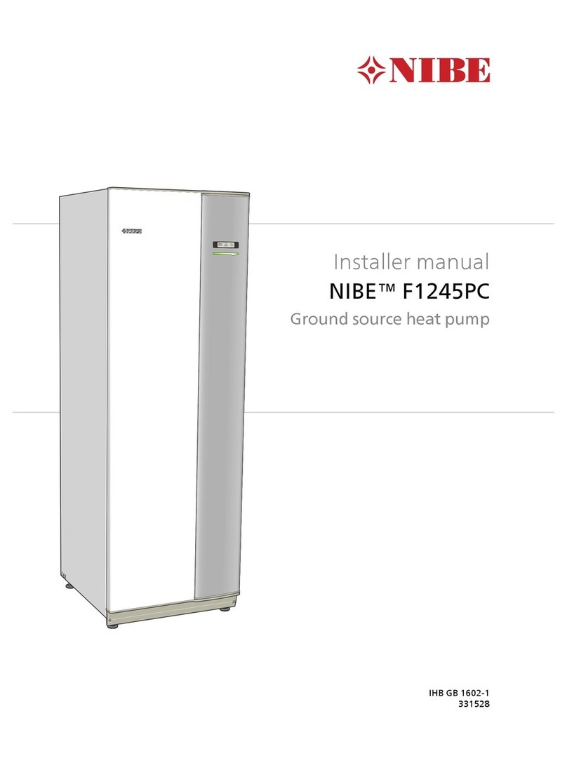
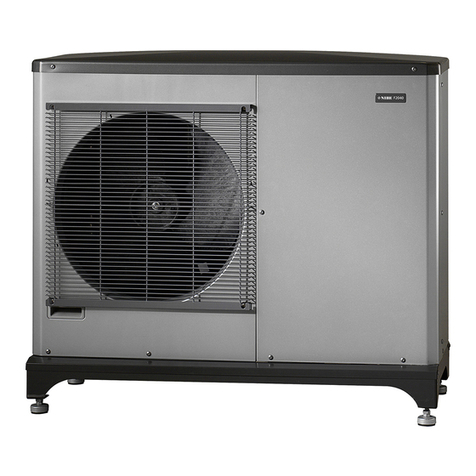
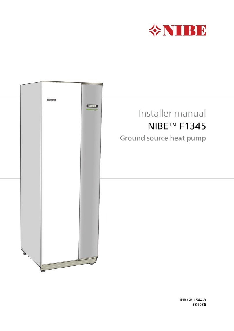
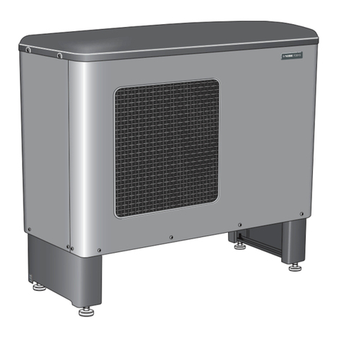
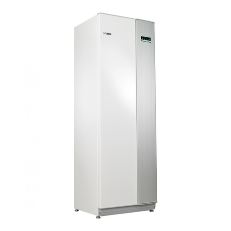
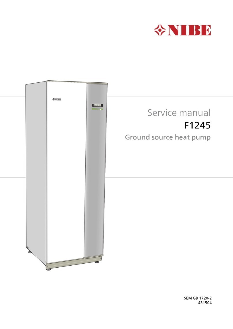
Nibe F1345 Series User manual

2 STAGE HEAT PUMP WITH ROCK,
EARTH, LAKE OR GROUND WATER
AS HEAT SOURCE.
• Less than 3 kg refrigerant per cooling section/installation.
This means no inspection requirement.
• The two scroll compressors can supply up to 65°C to the
heating system.
• Double compressors give better power control, longer oper-
ating intervals, less wear and greater operational security.
• Display unit with easy-to-read colour screen.
– See status and make settings via SMS with the SMS 40
accessory.
– Control the heat pump externally, with for example BMS,
via the accessory MODBUS 40.
• The heat pump is available in the following sizes: 24, 30, 40
and 60 kW.
• Up to 540 kW with 9 x F1345 in the same system.
• Soft start relays and load monitor factory installed.
• Internally installed low energy circulation pumps (not brine
pump for 40 or 60 kW).
• Prepared for pool heating with POOL 40 accessory.
• Prepared for control of up to four heating systems with
ECS40/ECS41 accessory.
• Coefficient Of Performance (COP) up to 4.51 at 0/35 C
according to EN 14511.
• Separate cooling modules for compressors and brine pumps
give reliable service and lower noise levels.
• Easy to remove the cooling modules.
• NIBE Uplink compatible
NIBE™ F1345
GROUND SOURCE HEAT PUMP
NIBE F1345
NIBE F1345 is a heat pump for heating large buildings, such as
apartment buildings, churches and industrial premises. F1345 is
a flexible product with advanced control equipment and can be
adapted to several system solutions. The ground, bedrock or lakes
can be used as the heat source. Groundwater can also be used as
a heat source, but this requires an intermediate heat exchanger.
Another area of use could also be ventilation recovery in multi-
occupancy buildings. F1345 can control up to four different
climate systems (requires accessory), for example a lower flow
temperature in the underfloor heating loops than in the radiators.
F1345 is also prepared for control of an external additional heater.
At hot water production this can be prioritised, selectable with
one or more compressors. This permits simultaneous production
of heat and hot water.

2 NIBE F1345
INSTALLATION METHOD
The term “ground source” covers four different heat sources:
rock, surface soil, ground water and lake.
Ground water
A viable energy source for any building
where ground water is easily accessible.
Ground water can also be utilised as a heat source since it
has a temperature of between 4 and 12°C all-year round. The
heat pump collects stored solar energy from the ground water.
Normally, there is one well for drawing up water and one for
returning it.
Lake collector
Cost-effective installation
for lakeside homes.
If your home is built beside a water source such as a lake, heat
from the lake water can be extracted using a surface soil collector
anchored to the bottom of the lake.
Rock - using a ground probe
Ideal for refurbishment or adaptation
from a fossil fuel heating system.
In the lower subsoil of the so-called “near-surface geothermal
layer” lies a heat source with an almost constant temperature
that can be utilised all year round. The heat pump collects stored
solar energy from a collector in a hole drilled into the rock. The
depth of the hole can vary between 90 – 200 metres, depending
on the size of heat pump selected. This type of system can be
used for all possible building types, large or small, public or
private. It requires little space and the ground probe can be drilled
in the smallest of gardens.
Surface soil - using a surface collector
Cost-effective energy collection.
During the summer, solar heat is stored in the soil. This is
either directly absorbed as insulation or as heat from rain and
the air from the near-surface layer of the soil. The heat pump
collects this stored solar energy from a buried collector. That is,
a hose filled with anti-freeze, and buried at a depth of about
80 – 100 cm, the length of the hose varies between 250 and
400 metres, depending on the size of heat pump selected.
Using this energy for heating is a cost effective method. The
highest yield can be obtained from soil with a high water content.

F1345 is extremely efficient thanks to a highly effective compressor
in well dimensioned refrigerant circuits. Internally installed low
energy circulation pumps and flex hoses (not brine pump for 40
or 60 kW). The brine respectively heating medium circuits are
connected from the rear of the heat pump. Particle filter supplied.
The heat pump can be connected to an optional low temperature
distribution system. e.g. radiators, convectors or under floor
heating. F1345 is equipped with a control computer for optimum
and reliable operation. A large backlit TFT display shows
information about status, operating time and all temperatures in
the heat pump as well as certain information about any slave heat
pumps, in colour using icons and text. F1345 is constructed on a
robust frame with durable panels and effective soundproofing for
the best possible comfort. All panels are easy to remove for easy
access when installing and for servicing.
NIBE F1345 3
Evaporator
Heating medium supply
Brine in
Brine in
Brine out
Brine out
Heating medium return
Condenser
* The brine pump (1 x) for 40 or 60 kW is supplied and installed externally
outside the heat pump.
Sleeve pipe
Brine to heat pump
Ground water level
Active borehole
(water column in
rock)
Brine from heat pump
40kW24-30kW 60kW40kW24-30kW 60kW
Circulation pump
Circulation pump
Expansion valveCooling module EP14
Cooling module EP15
Compressor
Compressor
Brine pump*
Brine pump*
F1345 consists of two heat pump modules (cooling module),
circulation pumps and control system with possibility of additional
heat. F1345 is connected to the brine and heating medium
circuits.
In the heat pump evaporator, the brine (water mixed with anti-
freeze, glycol or ethanol) releases its energy to the refrigerant,
which is vaporised in order to be compressed in the compressor.
The refrigerant, of which the temperature has now been raised,
is passed to the condenser where it gives off its energy to the
heating medium circuit and, if necessary, to any docked water
heater. If there is a greater need for heating/hot water than the
compressors can provide it is possible is to connect an external
immersion heater.
HOW DOES F1345 WORK?
Principle of operation

4 NIBE F1345
F1345 should be transported and stored vertically in a dry place.
When being moved into a building, F1345 may be leant back 45°.
NOTE! The heat pump is top heavy.
If the cooling modules are pulled out and transported upright,
F1345 can be transported on its back.
The side panels can be removed for easier installation in the
building.
R
0
+2
0
-2
1
R
0
HMflow
49(50)°C
Hotwater
51°C
+2
0
-2
1
R
0
HMflow
49(50)°C
Hotwater
51°C
R
0
• Position F1345 on a firm base that can take the weight,
preferably on a concrete floor or foundation. Use the heat
pump’s adjustable feet to obtain a stable set-up.
• Install with its back to an outside wall, ideally in a room
where noise does not matter, in order to eliminate noise
problems. If this is not possible, avoid placing it against a
wall behind a bedroom or other room where noise may be
a problem.
• Wherever the unit is located, walls to sound sensitive rooms
should be fitted with sound insulation.
• Route pipes so they are not fixed to an internal wall that
backs on to a bedroom or living room.
(50) (50)
800
NOTE! Ensure that the heat pump cannot fall
over during transport.
LEK
* A normal installation needs 300 - 400 mm (any side) for connection
equipment, i.e. level vessel, valves and electrical equipment.
**
To simplify transport and service, the heat pump can be separated
by pulling the cooling module out from the cabinet.
See the installer manual for comprehensive instructions about the
separation.
Leave a space of 800 mm in front of the heat pump.
Approximately 50 mm free space is required on each side
in order to open the side hatches. The hatches do not need
to be opened during service, all service on F1345 can be
carried out from the front. There must be at least 300mm of
free space above the heat pump. Leave space between the
heat pump and wall behind (and any routing of supply cables
and pipes) to reduce the risk of reproduction of any vibration.
GOOD TO KNOW ABOUT NIBE F1345
Transport and storage Assembly
Drawing out the cooling module
Installation area

NIBE F1345 5
GOOD TO KNOW ABOUT NIBE F1345
Dimensions
Pipe dimensions
Connections
(XL1) Heating medium supply, external thread G2”
(XL2) Heating medium return, external thread G2”
(XL6) Brine in, external thread G2”
(XL7) Brine out, external thread G2”
EP14-XL1
EP15-XL1
EP14-XL2
EP15-XL2
EP14-XL7
EP15-XL7
EP14-XL6
EP15-XL6
1775
600
560 440
735
1555
1715
80 145 145 145
450620
820
85
25-50

6 NIBE F1345
LEK
LEK
AA2
AA26
EP14-XL1
EP15-XL1
AA3
EP14-XL2
EP14-PF2
EP15-PF2
EP15-XL2
EP15-FB1
SF1
AA4-XJ4
AA4-XJ3
AA4
AA4
XJ10
XJ3
X7
XJ6
XJ9
UB3
X1
AA7
K1
XJ8
XJ7
EP14-XL7
EP15-XL7
UB1
X8 K4 K3 K2/K5
FC1
EP14-XL6
EP15-XL6
PF3
PF1
UB2
XJ2
XJ8
XJ7
EP15
EP14
XJ1
XJ5
XJ4
FC1 UB1UB2UB3X2 X3 X4 X5 X6
GOOD TO KNOW ABOUT NIBE F1345
Equipment

NIBE F1345 7
Pipe connections
XL1 Connection, heating medium flow
XL2 Connection, heating medium return
XL6 Connection, brine in
XL7 Connection, brine out
HVAC components
EP14 Cooling module
EP15 Cooling module
Sensors etc.
BT 1 Outside sensor
Electrical components
AA2 Base card
AA3 Input circuit board
AA4 Display unit
AA4-XJ3 USB outlet (no function)
AA4-XJ4 Service outlet (No function)
AA7 Extra relay circuit board
AA26 Base card 2
FC1 Miniature circuit-breaker
K1 Emergency mode relay
K2 Relay, external circulation pump (only 40 and 60 kW)
K3 Relay, external circulation pump (only 40 and 60 kW)
K4 Relay, external circulation pump (only 40 and 60 kW)
K5 Relay (only 24 and 30 kW)
X1 Terminal block, incoming electrical supply
X2 Terminal block, non-return valve, external brine pump
(only 40 and 60 kW) and external operating voltage
(at tariff control)
X3 Terminal block, step controlled additional heat
X4 Terminal block, emergency mode relay
X5 Terminal block, common alarm
X6 Terminal block, communication, sensors and software
controlled inputs
X7 Terminal block, control signal external brine pump
(only 40 and 60 kW)
X8 Terminal blocks
XJ 1 Connector, electrical supply to compressor,
cooling module EP14
XJ 2 Connector, electrical supply to compressor,
cooling module EP15
XJ 3 Connector, cooling module EP14
XJ 4 Connector, brine pump, cooling module EP14
(only 24 and 30 kW)
XJ 5 Connector, heating medium pump, cooling module
EP14
XJ 6 Connector, cooling module EP15
XJ 7 Connector, brine pump, cooling module EP15 (only 24
and 30 kW)
XJ 8 Connector, heating medium pump, cooling module
EP15
XJ 9 Connector, cooling module EP15
XJ 10 Connector, cooling module EP14
SF 1 Switch
Miscellaneous
PF1 Rating plate
PF2 Type plate, cooling section
PF3 Serial number plate
UB1 Cable gland, incoming electricity
UB2 Cable gland, power
UB3 Cable gland, signal
Designations in component locations according to standard IEC 81346-1 and
81346-2.
GOOD TO KNOW ABOUT NIBE F1345

8 NIBE F1345
The pump is adjustable, the flow can be adjusted in menu
5.1.11.
24 kW 30 kW
100
90
80
70
60
50
40
100%
80%
60%
40%
30
20
10
0
0 0,1 0,2 0,3 0,4 0,5 0,6 0,7 0,8 0,9
1,0
Eleffekt per cirkulationspump
W
Flöde, l/s
100
90
80
70
60
50
40
100%
80%
60%
40%
30
20
10
0
0 0,1 0,2 0,3 0,4 0,5 0,6 0,7 0,8 0,9
1,0
Eleffekt per cirkulationspump
W
Flöde, l/s
90
80
70
60
50
40
100%
80%
60%
40%
100%
80%
60%
40%
30
20
10
0
0 0,2 0,4 0,6 0,8 1,0 1,2 1,4 1,6 1,8
2,0
Externt tillgängligt tryck
kPa
2 cirkulationspumpar
1 cirkulationspump
Flöde, l/s
90
80
70
60
50
40
100%
80%
60%
40%
100%
80%
60%
40%
30
20
10
0
0 0,2 0,4 0,6 0,8 1,0 1,2 1,4 1,6 1,8
2,0
Externt tillgängligt tryck
kPa
2 cirkulationspumpar
1 cirkulationspump
Flöde, l/s
LE
K
GP1
External available pressure, kPa External available pressure, kPa
Electrical output per circulation pump, W Electrical output per circulation pump, W
Heating medium side
2 circulation pumps
1 circulation pump
2 circulation pumps
1 circulation pump
Flow, l/s
Flow, l/s
Flow, l/s
Flow, l/s
GOOD TO KNOW ABOUT NIBE F1345
Pump capacity diagram

NIBE F1345 9
40 kW 60 kW
100
90
80
70
60
50
40
100%
80%
60%
40%
30
20
10
0
0 0,1 0,2 0,3 0,4 0,5 0,6 0,7 0,8 0,9
1,0
Eleffekt per cirkulationspump
W
Flöde, l/s
100
90
80
70
60
50
40
100%
80%
60%
40%
100%
80%
60%
40%
30
20
10
0
0 0,2 0,4 0,6 0,8 1,0 1,2 1,4 1,6 1,8
2,0
Externt tillgängligt tryck
kPa
2 cirkulationspumpar
1 cirkulationspump
Flöde, l/s
100
90
80
70
60
50
40
100%
80%
60%
40%
30
20
10
0
0 0,2 0,4 0,6 0,8 1,0
1,2
Eleffekt per cirkulationspump
W
Flöde, l/s
100
90
80
70
60
50
40
100%
80%
60%
40%
100%
80%
60%
40%
30
20
10
0
0 0,2 0,4 0,6 0,8 1,0 1,2 1,4 1,6 1,8
2,0
Externt tillgängligt tryck
kPa
Flöde, l/s
2 cirkulationspumpar
1 cirkulationspump
The pump is adjustable, the flow can be adjusted in menu
5.1.11.
LEK
GP1
External available pressure, kPa External available pressure, kPa
Electrical output per circulation pump, W Electrical output per circulation pump, W
2 circulation pumps
1 circulation pump
2 circulation pumps
1 circulation pump
Flow, l/s
Flow, l/s
Flow, l/s
Flow, l/s
GOOD TO KNOW ABOUT NIBE F1345

10 NIBE F1345
24 kW 30 kW
200
180
160
140
120
100
80
100%
80%
60%
40%
60
40
20
0
0 0,2 0,4 0,6 0,8 1,0 1,2 1,4
Eleffekt per cirkulationspump
W
Flöde, l/s
120
100
80
60
40
100%
80%
60%40%
100%
80%
60%
40%
20
0
0 0,5 1,0 1,5 2,0
2,5
Externt tillgängligt tryck
kPa
Flöde, l/s
2 cirkulationspumpar
1 cirkulationspump
200
180
160
140
120
100
80
100%
80%
60%
40%
60
40
20
0
0 0,2 0,4 0,6 0,8 1,0 1,2 1,4
Eleffekt per cirkulationspump
W
Flöde, l/s
140
120
100
80
60
40
100%
80%
60%
40%
100%
80%
60%
40%
20
0
0 0,5 1,0 1,5 2,0
2,5
Externt tillgängligt tryck
kPa
2 cirkulationspumpar
1 cirkulationspump
Flöde, l/s
The pump is adjustable, the flow can be adjusted in menu
5.1.9.
LE
K
GP2
External available pressure, kPa External available pressure, kPa
Electrical output per circulation pump, W Electrical output per circulation pump, W
Brine side
2 circulation pumps
1 circulation pump
2 circulation pumps
1 circulation pump
Flow, l/s
Flow, l/s
Flow, l/s
Flow, l/s
GOOD TO KNOW ABOUT NIBE F1345
Pump capacity diagram

NIBE F1345 11
40 kW 60 kW
1,0
0,8
0,9
0,7
0,6
0,5
0,4
0,3
0,2
0,1
3
2
1
0
0 0,4 0,6 0,80,2 1,4 1,6 1,81,21,0 2,2 2,42,0
Eleffekt per cirkulationspump
kW
Flöde, l/s
180
160
140
120
100
80
60
40
3
2
1
20
0
0 0,4 0,6 0,80,2 1,4 1,6 1,81,21,0 2,2
2,4
2,0
Externt tillgängligt tryck
kPa
Flöde, l/s
1,4
1,2
1,0
0,8
0,6
0,4
0,2
3
2
1
0
0 0,5 1,0 1,5 2,0 2,5 3,0 3,5
Eleffekt per cirkulationspump
kW
Flöde, l/s
180
160
140
120
100
80
60
40
3
2
1
20
0
0 0,5 1,0 1,5 3,0
3,5
2,0 2,5
Externt tillgängligt tryck
kPa
Flöde, l/s
LEK
LEK
The pump is adjustable, the flow can be adjusted using the
speed switch on the pump.
External available pressure, kPa External available pressure, kPa
Electrical output per circulation pump, W Electrical output per circulation pump, W
Flow, l/s
Flow, l/s
Flow, l/s
Flow, l/s
GOOD TO KNOW ABOUT NIBE F1345
12 NIBE F1345
THE DISPLAY
Display unit
Display, A
Instructions, settings and operational information are shown on
the display. The easy-to-read display and menu system, facilitates
navigation between the different menus and options to set the
comfort or obtain the information you require.
Status lamp, B
The status lamp indicates the status of the heat pump. It:
• lights green during normal operation.
• lights yellow in emergency mode.
• lights red in the event of a deployed alarm.
OK button, C
The OK button is used to:
• confirm selections of sub menus/options/set values/page in
the start guide.
Back button, D
The back button is used to:
• go back to the previous menu.
• change a setting that has not been confirmed.
Control knob, E
The control knob can be turned to the right or left. You can:
• scroll in menus and between options.
• increase and decrease the values.
• change page in multiple page instructions (for example help
text and service info).
Switch, F
The switch assumes three positions:
• On ()
• Standby ( )
• Emergency mode ( )
A large, easy to read multicoulour display gives everyone the chance to
maximize the energy saving potential of this exciting green technology!
BStatus lamp
ADisplay
COK button
DBack button
EControl knob
FSwitch
F1345

NIBE F1345 13
THE DISPLAY
Menu system
When the door to the heat pump is opened, the menu system’s
four main menus are shown in the display as well as certain basic
information.
Menu 1 – Indoor climate
Setting and scheduling the indoor climate.
Menu 2 – Hot water
Setting and scheduling hot water production.
This menu only appears if a water heater is docked to the heat
pump.
Menu 3 - Info
Display of temperature and other operating information and
access to the alarm log.
Menu 4 – Heat pump
Setting time, date, language, display, operating mode etc.
Menu 5 - Service
Advanced settings. These settings are not available to the user.
The menu is visible by pressing the back button for 7 seconds.
Start guide
The first time the heat pump is switched on a start guide is
started. The start guide instructions state what needs to carried
out at the first start together with a run through of the heat
pump’s basic settings.
The start guide ensures that the start-up is carried out correctly
and cannot be bypassed. The start guide can be started later in
menu 5.7.
Indoor temperature -
(if a room sensor is
connected)
Outdoor temp. Hot water temp.
Extra hot water
(if activated)
Estimated amount of
hot water

14 NIBE F1345
Pipe installation
Pipe installation must be carried out in accordance with
current norms and directives. F1345 can operate with a return
temperature of up to 58 °C and an outgoing temperature from
the heat pump of 65 °C.
F1345 is not equipped with shut off valves; these must be
installed outside the heat pump to facilitate any future servicing.
Pipe connection (cooling medium)
The pipe connections are on the rear of the heat pump.
Insulate all indoor brine pipes against condensation.
Mark the brine system with the antifreeze that is used.
Install the supplied safety valve at the expansion vessel as
illustrated in the outline diagram. The entire length of the
overflow water pipe from the safety valves must be inclined to
prevent water pockets and must also be frost-free.
Install shut off valves as close to the heat pump as possible so
that the flow to individual cooling modules can be shut off.
Extra safety valves between the particle filter and shut off valves
(according the outline diagram) are required.
Fit the supplied particle filter on the incoming brine pipe. Fit the
supplied non-return valves on the outgoing pipe. In the case of
connection to an open groundwater system, an intermediate
frost-protected circuit must be provided, because of the risk of
dirt and freezing in the evaporator. This requires an extra heat
exchanger.
PP
Pressure expansion vessel
The brine circuit must be supplied with a pressure expansion
vessel.
The brine side must be pressurised to at least 0.05 MPa (0.5 bar).
The pressure expansion vessel should be dimensioned as set out
in the following diagram, to prevent operating disturbances. The
diagrams cover the temperature range from -10 °C to + 20 °C
at a pre-pressure of 0.05 MPa (0.5 bar) and the safety valve's
opening pressure of 0.3 MPa (3.0 bar).
Ethanol 28% (volume percent)
In installations with ethanol (28% volume percent) as the brine,
the pressure expansion vessel must be dimensioned according to
the following diagram.
Ethylene glycol 40% (volume percent)
In installations with ethylene glycol (40% volume percent) as the brine
the pressure expansion vessel must be dimensioned according to the
following diagram.
0 200 400 600 800 1000 1200 1400 1600 1800 2000
0
10
20
30
40
50
60
70
80
90
100
Volume pressure expansion vessel (l)
Total volume refrigerant in system (l)
30
0
40
50
60
0
10
20
100 200 300 400 500 600 700 800900 1000 1100 1200 1300 1400 1500
Volume pressure expansion vessel (l)
Total volume refrigerant in system (l)
Ethylene glycol 40% (volume percent)
In installations with ethylene glycol (40% volume percent) as the brine
the pressure expansion vessel must be dimensioned according to the
following diagram.
INSTALLATION
Note! Note that condensation may drip from the
level
vessel. Position the vessel so that this does not harm
other equipment.

NIBE F1345 15NIBE VPB 200N 15
Connection of external brine pump
(only 40 and 60 kW)
Install the brine pump (GP16) according to the circulation pump
manual for connection of incoming brine (EP14-XL6) and (EP15-
XL6) between the heat pump and shut off valve (see image).
Pipe connection (heating medium)
Connecting the climate system
A climate system is a system that regulates indoor comfort with
the help of the control system in F1345 and for example radiators,
underfloor heating/cooling, fan convectors etc.
The pipe connections are on the rear of the heat pump.
Install the necessary safety equipment and shut off valves
(installed as close to the heat pump as possible so that the flow
to individual cooling modules can be shut off).
Fit the supplied particle filter on the incoming pipe.
The safety valve must have a maximum 0.6 MPa ( 6.0 bar)
opening pressure and be installed on the heating medium return.
The entire length of the overflow water pipe from the safety
valves must be inclined to prevent water pockets and must also
be frost-free.
When connecting to a system with thermostats on all radiators,
a relief valve must be fitted, or some of the thermostats must be
removed to ensure sufficient flow.
Fit the supplied non-return valves on the outgoing pipe.
Install the vent valves in the climate system if necessary.
CAUTION! When necessary you should install
venting valves in the climate system.
CAUTION! The heat pump is designed so that
heating production can occur with one or two
cooling modules. This however entails different
pipe or electrical installations.
40kW24-30kW 60kW40kW24-30kW 60kW
GP16
Pipe connection (water heater)
• Any docked hot water heater must be fitted with necessary
set of valves.
• The mixing valve must be installed if the setting is changed
so that the temperature can exceed 60 °C.
• The setting for hot water is made in menu 5.1.1.
• The safety valve must have a maximum opening pressure in
accordance with the water heater manual and be installed on
the incoming domestic water line. The entire length of the
overflow water pipe from the safety valves must be inclined
to prevent water pockets and must also be frost-free.
Fixed condensing
If F1345 is to work towards the water heater with fixed condensing you
must connect an external flow sensor (BT25) according to the descrip-
tion in the installer handbook In addition, menu settings must be made
(see installer handbook).
CAUTION! The heat pump/system is
designed so that hot water production can
occur with one or several cooling modules.
This however entails different pipe or electrical
installations.
INSTALLATION

16 NIBE F1345
NIBE F1345 can be connected in several different ways, some of which are shown
below. Further option information is available in the respective assembly instruc-
tions for the accessories used.
-BT6
-EB100-BT7
-CP10
-EP12
-CM3
P
-BP6 -QM21 -FL3
-XL28-XL27
-QM33
-FL2
-CM1
-QM11 -QM20
-QM34
-EB100-BT25
-EB100-BT71
-FL12
-FL11
-FL13
-FL14
-QM54
-QM55
-QM56
-QM57
-QM50
-QM51
-QM52
-QM53
-RM11
-RM10
-BT1
>-EB100
-EB100
-EB100
-EP15
-EP14
-HQ15
-HQ14
-RM12
-RM13
-HQ13
-HQ12
-EB100
-CM5
-FL10
-QM42
-QM43
-EB1
-EB1
-EB2
-XD1
-RN11
-QN10
-EB100
-GP10
-KA1
-AA25
-RM42
F1345 docked with electric additional heat and water
heater
(floating condensing)
The heat pump (EB100) prioritises charging of hot water with half
the power (cooling module EP14) via a reversing valve (QN10).
When the water heater/accumulator tank (CP10) are fully
charged (EB100-QN10) switches to the heating circuit. When
there is a demand for heat, cooling module (EP15) starts first. For
greater demands, cooling module (EP14) also starts for heating
operation.
Additional heat (EB1) is connected automatically when the energy
requirement exceeds the heat pump capacity.
If the water heater/accumulator tank (CP10) is fitted with an
immersion heater (EB2) and a junction box (XD1) and the accessory
card AXC 50 (AA5), the functions "temporary lux" and "periodic
increase" can be used. A by-pass contactor is recommended.
INSTALLATION

NIBE F1345 17
2x F1345 docked with oil addition, pool and water heater
(floating condensing)
The heat pump (EB100) prioritises charging of hot water with
half the power (cooling module EP14) via a reversing valve
(EB100-QN10). When the water heater/accumulator tank (CP10
and CP11) are fully charged (EB100-QN10) switches to the
heating circuit. The other half of the output (cooling module
EP15) prioritises pool heating via a reversing valve (CL11-QN19).
When the pool is heated (CL11-QN19) switches to the heating
circuit. When there is a demand for heat, cooling module (EP15)
starts in heat pump (EB101) first. For greater demands, cooling
module (EP14) also starts in (EB101) for heating operation.
Additional heat (EM1) is connected automatically when the
energy requirement exceeds the heat pump capacity.
If the water heater/accumulator tank (CP10) is fitted with an
immersion heater and a junction box the function "temporary
lux" is used. A by-pass contactor is recommended.
-HQ13
-RM11
-HQ12
-RM10
-HQ15
HQ14
-RM12
-RM13
>-EB101
-EB101
-EP15
-EP14
-EP12
-CM3
P
-BP6 -QM21 -FL3
-XL28-XL27
-QM33
-EB100-BT25
-FL2
-CM1
-QM11 -QM20
-EB100-BT71
-QM34
-QM54
-QM55
-QM56
-QM57
-FL13
-FL14
-FL13
-FL14
-QM50
-QM51
-QM52
-QM53
-FL11
-FL12
-QM54
-QM55
-QM56
-QM57
-QM50
-QM51
-FL11
-QM52
-QM53
-FL12
-QN10
-QN19
-CL11
-AA5
-RN42
-EP5
-GP9 -BT51 -HQ41 POOL
-BT6
-EB100-BT7
-CP10
-RN63
-RN62
-CP11
-RN61
-RN60
-RM42
-GP10
-QN11
-BT52 -AA5
-CM5
-FL10
-EM1
-EM1
-KA1 -BT3
-BT2
-EP21
-GP20
-QN25
-AA5
-HQ13
-EB100
-EB100
-RM11
-HQ12
-RM10
-BT1
>-EB100
-EB100
-EB100
-EP15
-EP14
-HQ15
-HQ14
-RM12
-RM13
-AA5 -GP11
-RN41
-RN42
-RM44
-RM43
-EB10
-FQ1
-BT70
INSTALLATION

18 NIBE F1345
Inspection of the installation
Current regulations require the heating installation to be
inspected before it is commissioned. The inspection must
be carried out by a suitably qualified person and should be
documented. The above applies to closed heating systems. If the
heat pump is replaced, the installation must be inspected again.
Guideline values for collectors
Type Surface ground heating,
recommended
collector length
Ground-source heating,
recommended
active drilling depth
24 3x350 – 3x400 m 2x180 – 3x180 m
30 3x450 – 4x450 m 3x150 – 5x150 m
40 4x500 – 6x500 m 4x170 – 5x200 m
60 6x450 – 8x450 m 6x150 – 8x180 m
For use with 40 x 2.4 PN 6.3 PEM hose.
This are rough example values. On installation the correct
calculations must be made according to local conditions.
The length of the collector hose varies depending on the rock/soil
conditions, climate zone and on the climate system (radiators or
underfloor heating).
Max length per coil for the collector should not exceed 500 m.
The collectors must always be connected in parallel with the
possibility of adjusting the flow for the relevant coil.
For surface soil heat, the hose should be buried at a depth of
about 1 metre and the distance between the hoses should be at
least 1 metre.
For several bore holes, the distance between the holes must be
at least 15 m.
Ensure the collector hose rises constantly towards the heat pump
to avoid air pockets. If this is not possible, air vents should be
used.
As the temperature of the brine system can fall below 0 °C it
must be protected against freezing down to -15 °C. One litre
of ready mixed brine per meter of collector hose (applies when
using PEM-hose 40 x 2.4 PN 6.3) is used as a guide value when
making the volume calculation.
Control, general
The indoor temperature depends on several factors. Sunlight
and heat emissions from people and household machines are
normally sufficient to keep the house warm during the warmer
parts of the year. When it gets colder outside, the climate system
must be started. The colder it is outside, the warmer radiators and
floor heating system must be.
The heat pump is controlled by built-in sensors for flow and
return brine temperatures (collector). Brine return temperatures
can, if so required, be limited to a minimum (e.g. for ground
water systems).
Control of the heat production is performed based on the
"floating condensing" principle, i.e. the temperature level needed
for heating at a specific outdoor temperature is produced guided
by collected values from the outdoor and flow sensors. The room
temperature sensor can also be used to compensate the deviation
in room temperature.
F1345 can be docked to an external unit with its own heating
controls. In that case, the heat pump delivers heat up to a
fixed temperature level. This is known as “Fixed condensing”.
The automatic heating control system is then controlled by the
external unit’s regulation device.
INSTALLATION

NIBE F1345 19
Basic functions
Heat production
F1345 is equipped with an outdoor temperature controlled
heating control system. This means that the supply of heat to the
house is regulated in accordance with the chosen setting of the
regulating curve (curve slope and offset). After adjustment, the
correct amount of heat for the outside temperature is supplied.
The flow line temperature of the heat pump will hunt around
the theoretically required value. For subnormal temperatures the
control system calculates a heating deficit in the form of "degree-
minutes" which means that heating production is accelerated.
The larger the subnormal temperature, the greater the heat
production.
Heat production can take place with one or several compressors.
Hot water production
This function requires accessory VST 20.
If the water heater is docked to F1345 when there
is a demand for hot water, the heat pump gives
this priority and devotes half its output to water
heating. Heating is produced by the second compressor in this
mode. Maximum time for hot water charging can be adjusted
in the menu system. After this, heating is produced by both the
compressors for the remaining period of time before further
water heating can take place.
With two or more compressors connected for water heating this
is engaged and disengaged automatically by the control system
on demand. A reversing valve is required for each F1345 that is
to charge hot water.
Hot water charging starts when the hot water sensor has fallen
to the set start temperature. Hot water charging stops when the
hot water temperature on the hot water sensor (BT6) has been
reached.
For occasional higher demand for hot water, the temporary lux
function can be used to raise the temperature for 3 – 12 hours
(selected in the menu system).
Own curve
F1345 has pre-programmed non linear heating curves. It is also
possible to create your own defined curve. This is an individual
linear curve with one break point. You select a break point and
the associated temperatures.
Under floor drying
F1345 has an integrated floor drying function. This allows for
controlled drying of a concrete slab. It is possible to create
your own program and to follow a pre-programmed time and
temperature schedule.
LEK
LEK
LEK
Brine pump
The brine pumps (40 or 60 kW have 1 brine pump) normally follow the
operation of the heat pump. There is a special operating mode for con-
tinuous operation for 10 days, followed by return to normal mode (this
may be used before stable circulation has been established).
Alarm indications
The status lamp lights red in the event of an alarm and the display
shows detailed information depending on the fault. An alarm log is cre-
ated with each alarm containing a number of temperatures, times and
the status of outputs.
Additional heat only
F1345 can be used exclusively with an additional heater to produce
heat, for example before the collector installation is complete.
Room control
F1345 can be supplemented with a room sensor (BT50). The room tem-
perature sensor has up to three functions:
1. Show current room temperature in the heat pump's display.
2. Option of changing the room temperature in °C.
3. Makes it possible to change/stabilise the room temperature.
Install the sensor in a neutral position where the set temperature is
required. A suitable place is on a free inner wall in a hall approx. 1.5 m
above the floor. It is important that the sensor is not obstructed from
measuring the correct room temperature by being located, for example,
in a recess, between shelves, behind a curtain, above or close to a heat
source, in a draft from an external door or in direct sunlight. Closed
radiator thermostats can also cause problems.
The heat pump operates without the sensor, but if one wishes to read
off the accommodation's indoor temperature in F1345's display the sen-
sor must be installed.
External control (AUX input)
F1345 can be controlled using signals from external systems (for exam-
ple DUC) connected to three software controlled inputs (AUX inputs).
The alarm and time conditions in F1345 override the external control.
The following functions can be controlled:
• Blocking of the compressors -EP14 and -EP15
• Blocking additional heat
• Blocking heating
• Tariff blocking
• Activation of temporary lux (extra hot water)
• External adjustment of flow temperature
• Forced control of brine pump(s)
• Activating fan speed (requires accessory NIBE FLM)
All control signals should occur with potential-free relays.
INSTALLATION

20 NIBE F1345
Step controlled additional heat
Heat pumps are not usually dimensioned to provide the entire heat out-
put requirement, which is why additional output is necessary during cold
days. The external step controlled additional heater (if connected) is au-
tomatically switched on (in different steps) if the output is not sufficient
to reach the temperature levels requested by the control computer.
F1345 provides 230 V control signals for the additional heat, that is
signals for controlling external relays, contactors etc, but not to supply
them with power.
External step controlled additional heat can be controlled by up to three
potential free relays in the heat pump (3 step linear or 7 step binary).
With the AXC 50 accessory a further three potential free relays are used
for addition control, which then gives max 3+3 linear or 7+7 binary
steps.
Step in occurs with at least 1 minute interval and step outs with at least
3 seconds interval.
Master/Slave
Several heat pumps (F1345) can be interconnected by selecting one heat
pump as master and the others as slaves.
The heat pump is always delivered as master and up to 8 slaves can be
connected to it and supply up to 540 kW (with 9 x F1345 60 kW) in the
same system. In systems with several heat pumps each pump must have
a unique name, that is only one heat pump can be "Master" and only
one can be for example "Slave 5".
External temperature sensors and control signals must only be connect-
ed to the master, except for external control of the compressor module
and reversing valve(s) (QN10) that can be connected one to each heat
pump.
Software controlled output (AUX output)
It is possible to have an external connection through the relay function
via a potential free variable relay (max 2 A) on the X5 terminal block.
Optional functions for external connection:
• Indication of buzzer alarm (preselected at the factory).
• Controlling ground water pump.
• Cooling mode indication (only applies if accessories for cooling are
present or if the heat pump has the integrated cooling function).
• Control of circulation pump for hot water circulation.
• External circulation pump (for heating medium).
• If any of the above is installed to terminal block X5 it must be
selected in the control system.
The accessory card is required if two or more of the above functions are
to be connected to terminal block X5 at the same time.
Load monitor
When many power consumers are connected in the property at the
same time as the electric additional heat is operating, there is a risk of
the property's main fuse tripping. The heat pump has integrated load
monitors that control the electrical steps for the electrical additional heat
by disconnecting step by step in event of overload in a phase. Reconnec-
tion occurs when other current consumption is reduced.
A current sensor should be installed on each incoming phase conductor
in to the distribution box to measure the current. The distribution box is
an appropriate installation point.
USB service outlet
F1345 is equipped with a USB socket in the display unit. This USB socket
can be used to connect a USB memory stick to update the software,
save logged information and handle the settings in F1345.
LEK
INSTALLATION
Other manuals for F1345 Series
8
Table of contents
Other Nibe Heat Pump manuals
Popular Heat Pump manuals by other brands

Daikin
Daikin INTERGAS Altherma EJHA-AV3 installation manual

International comfort products
International comfort products R- 410A installation instructions

Danfoss
Danfoss DHP-AT user guide

poolstar
poolstar Poolex Silverline FI Series Installation and user manual

Panasonic
Panasonic Aquarea WH-ADC1216H6E5 Service manual

Marstair
Marstair MMC Technical manual

Panasonic
Panasonic WH-SDF09C3E8 Service manual

LG
LG LD187HHV4 Engineering manual

Carrier
Carrier 38QV024320 Operation, Service and Troubleshooting

Sanyo
Sanyo 42XHW72R Specifications

Dimplex
Dimplex LA 60TU Nstallation and operating instructions

Nortek
Nortek GXH09KSK4DH Owner's manual and installation instructions