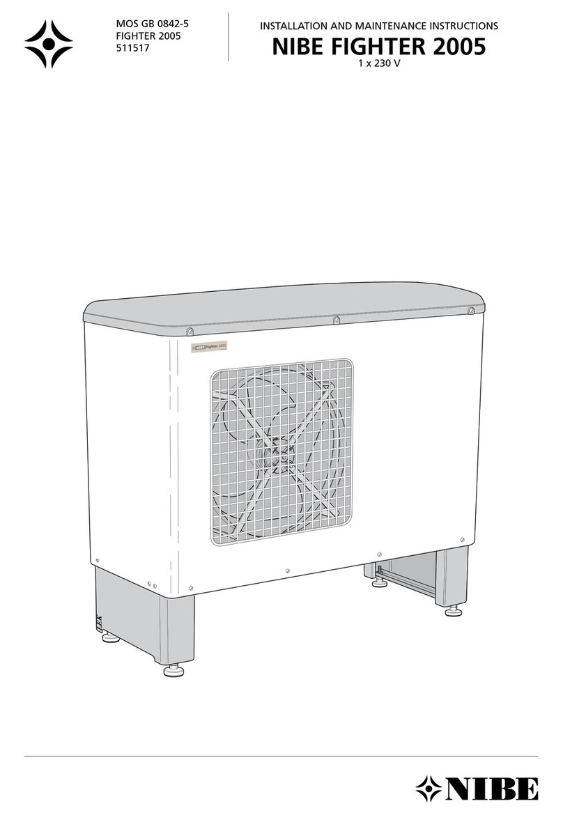
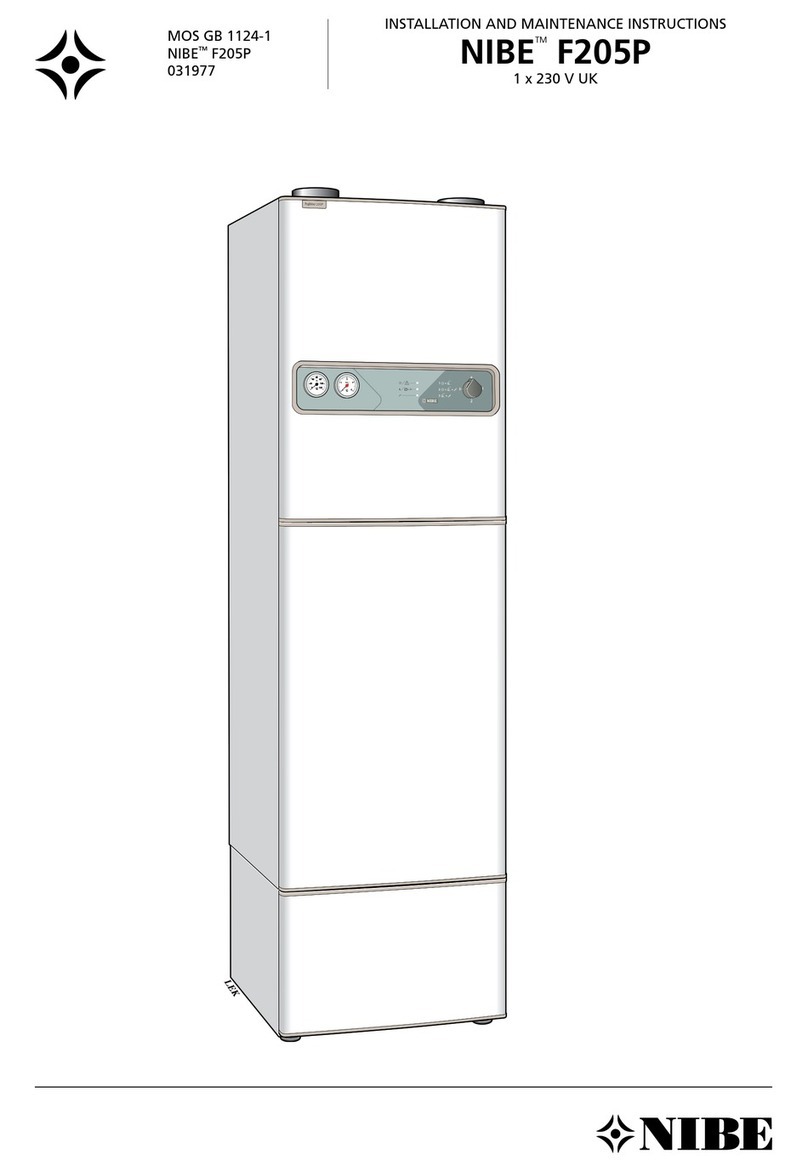
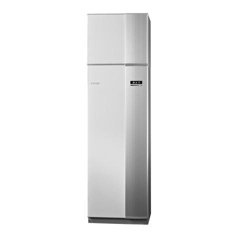
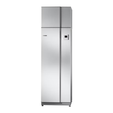
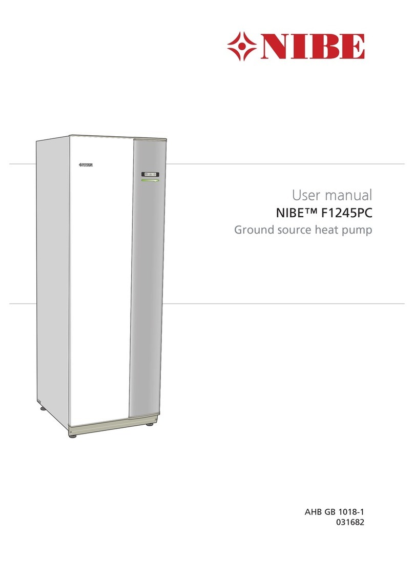
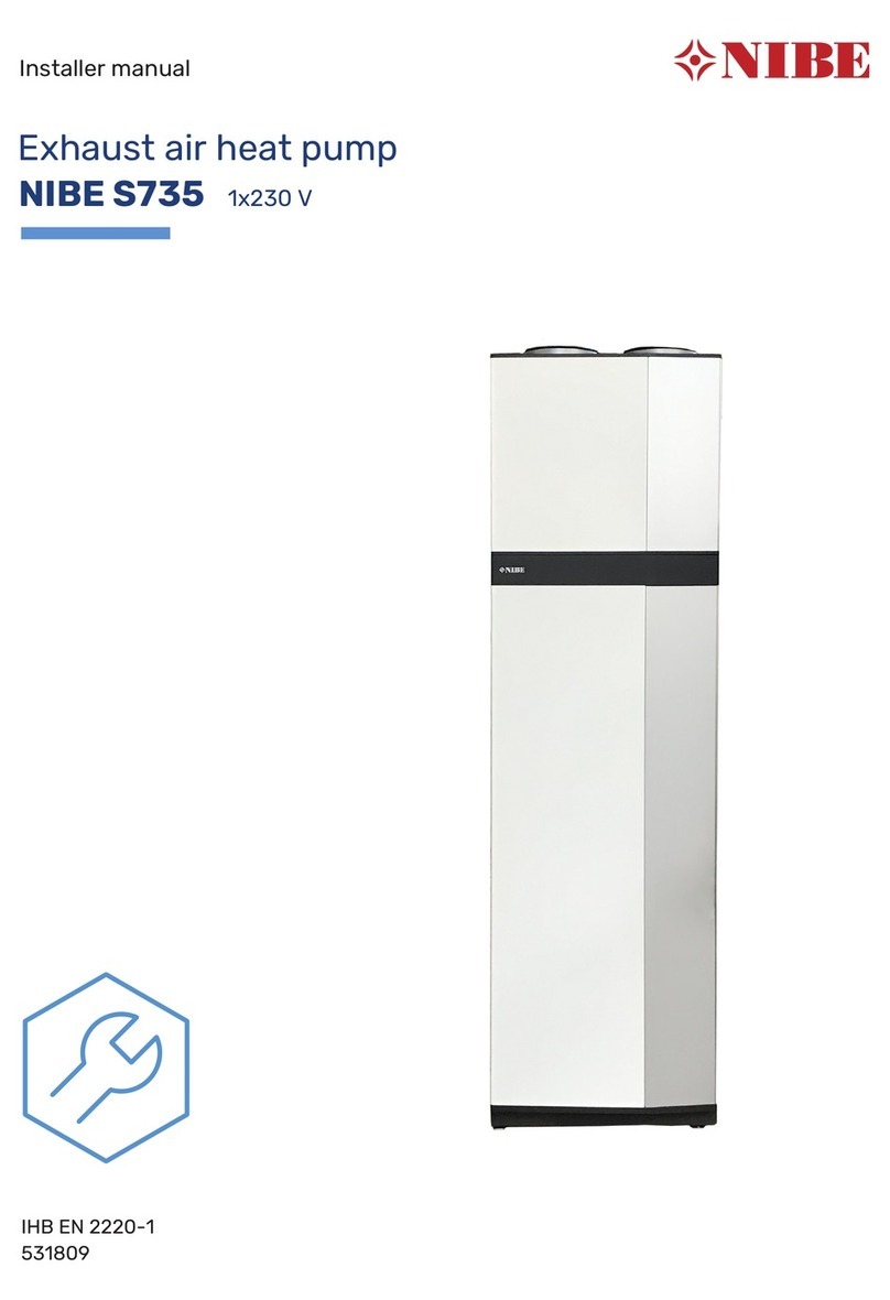
Nibe FIGHTER 1120 User manual

INSTALLATION AND MAINTENANCE INSTRUCTIONS
FIGHTER 1120
MOS GB 0429-1 611922
FIGHTER 1120
LEK
R


For the Installer
Contents 1
FIGHTER 1120
For Home Owners
General points for the installation engineer
Transport and storage .................................................. 9
Installation .................................................................... 9
Floating condensing .................................................... 9
Fixed condensing ........................................................ 9
Guideline values for collectors .................................... 9
Inspection of the installation ........................................ 9
Pipe connections
General ...................................................................... 10
Heating medium pump .............................................. 10
Pipe connection (brine) .............................................. 10
Pipe connection (heating medium) ............................ 10
Ventilation recovery .................................................... 10
Free cooling ................................................................ 10
Pump capacity diagrams, heating medium side ........ 11
Pump capacity diagrams, brine side .......................... 12
Electrical connections
Removing the covers ................................................ 13
Connection ................................................................ 14
Connection on delivery .............................................. 15
Tariff connection ........................................................ 15
Connecting the outside sensor .................................. 16
Connecting the temperature sensor included for
hot tap water ............................................................ 16
Connecting the supplied temperature sensor with
fixed condensing .................................................... 16
Connecting the supplied sensor for external
compensation .......................................................... 16
Max hot water temperature ........................................ 17
Max phase current ...................................................... 17
Centralised load control and load monitor ................ 18
Docking
General ...................................................................... 19
Abbreviations .............................................................. 19
Option 1 – immersion heater and water heater ........ 20
Option 3 – oil-fired boiler ............................................ 22
Option 4 – another heat source ................................ 24
Commissioning and adjusting
Preparations .............................................................. 26
Filling and venting the cooling medium system ........ 26
Filling the heating/heating medium systems ............ 26
Soft-start relay ............................................................ 26
Starting and checking ................................................ 27
Readjustment, heating medium side ........................ 27
Readjustments, brine side ........................................ 27
Setting the automatic heating control system
Setting using diagrams .............................................. 28
Heating curve offset -2 .............................................. 28
Heating curve offset 0 ................................................ 28
Heating curve offset +2 .............................................. 28
Controls
General........................................................................ 29
Key lock ...................................................................... 29
Quick movement ........................................................ 29
Changing parameters ................................................ 30
Menu tree .................................................................... 31
Main menus ................................................................ 34
Hot water temperature ................................................ 35
Supply temperature .................................................... 36
Outside temperature .................................................. 38
Brine flow/return.......................................................... 38
Clock............................................................................ 39
Other settings.............................................................. 41
Service menus
Settings additional heat .............................................. 43
Operating settings ...................................................... 44
Quick start ....................................................................47
TEST Force driven operation...................................... 47
Alarm log .................................................................... 47
Alarm indications on the display ................................ 48
Dealing with malfunctions
Alarm indications on the display .............................. 49
Low hot water temperature or no hot water ............ 50
Low room temperature ............................................ 50
High room temperature ............................................ 50
Helping the circulation pump to start ........................ 51
Draining, heat medium side .................................... 51
Draining, brine side.................................................... 51
Component locations
Component locations ................................................ 52
List of components
List of components .................................................... 53
Electrical circuit diagram
Wiring diagram 3 x 400 V + N .................................... 54
Dimensions
Dimensions and setting-out coordinates .................. 58
Technical specifications
Technical specifications ............................................ 59
Enclosed kit
Enclosed kit ................................................................ 60
Accessories ................................................................ 60
General
Concise product description ................................ 2
Setting table ........................................................ 2
System description
Principle of operation .......................................... 3
Front panel
Layout .................................................................. 4
Explanation .......................................................... 4
Setting different operating modes (even with
accessories) ...................................................... 5
Room temperature
Automatic heating control system ........................ 6
Default setting ...................................................... 6
Changing the room temperature .......................... 6
Basic values for the automatic heating control
system ................................................................ 7
Heat production .................................................... 8
Domestic hot water .............................................. 8
Electric boiler mode .............................................. 8
Brine pump .......................................................... 8
Fixed condensing ................................................ 8
Standby mode “ ” ............................................ 8

General
FIGHTER 1120
For Home Owners
2
In order to get the ultimate benefit from your heat pump
FIGHTER 1120 you should read through the For Home
Owners section in this Installation and Maintenance
Instruction.
FIGHTER 1120 is a base heat pump for heating small hous-
es, apartment blocks and industrial premises. The ground,
rock or lakes can be used as the heat source.
FIGHTER 1120 is a Swedish made quality product offer-
ing a long life span and safe operation.
Installation date
Accessories:
Electrical supplement ...... ■■
Hot water control ............ ■■
Oil supplement ................ ■■
Room control .................. ■■
Other .............................. ■■
The serial number (95), should always be stated with all
correspondence with NIBE.
689
___________
(e.g. 68922329454897)
FIGHTER 1120-
__
kW
Installation engineers
Completedby the installer when the heat pump is installed
The type of brine Mixing proportion/freezing point
Active drilling depth/collector length
Commissioning checks
Temperature brine (flow/return)__ / __ Pump setting _
(Nominal temperature diff 2 - 5 °C)
Temperature heat medium (in/out) __ / __ Pump setting __
(Nominal temperature diff 5 - 10 °C)
Settings
* Accessories ** Electric boiler mode (see Menu 14).
Date ________Signed ______________________________
Menu Basic
setting
1.4 Start temp. HW*..............
1.5 Stop temp. HW*.............. 54
1.6
Stop temp. XHW*
............ 60
1.8
Interval period XHW*
........ 14
2.1 Curve slope .............. 9
2.2 Offset. heating curve ...... 0
2.3
Flow temp/MIN
.............. 15
2.4
Flow temp/MAX
.............. 55
Position Basic
setting
100
“Fuse”
.............. 20
101
“Max electrical output”
.... C
102
“Max boiler temp”
............ 65

FIGHTER 1120 consists of a heat pump, circulation
pumps and a control system for the heat pump and
any additional heat (an immersion heater is not includ-
ed in the basic design).
FIGHTER 1120 has built-in circulation pumps, making
it easy to connect to the heating medium and collector
circuits.
The absorption of heat from the heat source (rock,
ground or lake) is through a closed collector system
containing water mixed with antifreeze.
Ground water can also be used as a heat source. This
requires an intermediate heat exchanger.
The brine emits its heat to the refrigerant in the heat
pump’s evaporator. It then vaporises and is com-
pressed in the compressor. The refrigerant, with its
increased temperature, is led into the condenser
where it emits its energy to the heat medium circuit.
System description 3
For Home Owners
FIGHTER 1120
Principle of operation
Köldbärare
(KB)-retur
Värmebärare
(VB), returKompressor
Markkollektor Bergkollektor
Värmebärare
(VB), fram
Värmebärar-
pump
Kondensor
Expansionsventil
Köldbärare
(KB)-fram
Förångare
Köldbärar-
pump
The installation must be fitted with the
necessary safety equipment in accor-
dance with the applicable regulations.
Compressor Heating water return
Heating water flow
Heating water pump
Condensor
Evaporator
Horizontal loop collector Vertical loop collector
Brine pump
Brine in
Brine out
Expansion valve

Front panel
For Home Owners
4
A BI II III I II
50.0 C
Hotwatertemperature
13.43
1.0
A
Display
Power switch
Left-hand
buttons
Offset heating
curve
Layout
A
B
C
D
Right-hand
buttons
E
Explanation
Switch
with three positions 1 - 0 - :
1Normal mode. All control functions connected.
0 Boiler completely switched off.
Standby. Only circulation pump and electrical
supplement. Not connected at the factory
The switch must not be turned to 1 or “”
before filling the boiler with water.
A
Display First row:
Compressor symbol.
Indicates when the compressor is opera-
tional.
Additional symbol
Indicates when immersion heater is con-
nected. The line indicates which power
step/steps are currently connected.
IAdditional power, step 1 enabled.
II Additional power, step 2 enabled.
I II Additional power, step 3 enabled.
B
I II III
A
Extra hot water symbol.
Indicates when the Extra hot water function
is active.
Ais shown when temperature increase is
active.
Bis shown when a time based tempera-
ture increase is activated, for example.
periodic.
Circulation pump symbol.
IShown when the circulation pump is
operational.
II Shown when circulation pump 2 is oper-
ational (accessory, extra shunt group
required).
Heating system symbols.
Shown when house heating is in progress.
A B
I II
FIGHTER 1120

Front panel 5
For Home Owners
FIGHTER 1120
Left-hand buttons
C
Operating mode
This button is used to set the required
operating mode with regard to permit-
ting/blocking the circulation pump and
additional energy. The change does not
need to be confirmed with the Enter
button.
The different operating modes are:
Auto mode:
FIGHTER 1120 automatically selects the operating
mode by taking the outdoor temperature into account.
The circulation pump and the immersion heater are
permitted to run as needed.
Summer mode:
Only production of hot water using FIGHTER 1120.
The circulation pump and immersion heater are
blocked. However, when Extra hot water is activated
the immersion heater is connected.
Spring/Autumn mode:
Only production of heating and hot water using
FIGHTER 1120. The circulation pump is operational.
The immersion heater is disabled. However, when
Extra hot water is activated the immersion heater is
connected.
The current operating mode is shown on the display
when the button is pressed and the mode changes
when you continue to press the button. The display
returns to the normal display mode once the enter but-
ton is pressed.
Winter mode:
Production of heating and hot water.
Display
Second row: Value of the current parameter.
Third row: Description of current display para-
meter. Hot water temp is normally
shown.
Fourth row: Shows menu numbers, key lock,
clock symbol and time
B
A key lock can be activated in the main
menus by simultaneously pressing the
Plus and the Minus buttons. The key
symbol will then be shown on the dis-
play. The same procedure is used to
deactivate the key lock.
The symbol becomes visible when a
timer function is selected, for example,
periodic lowering of the supply or time
setting for extra hot water.
1
Right-hand buttons
Offset heating curve
D
E
Extra hot water
The Extra hot water function is activat-
ed using this button. The change does
not need to be confirmed with the enter
button.
A:
Means that the hot water temperature is increased
to 60 °C (adjustable). The temperature then returns to
the normal value.
When Acomes on the function is activated.
When Agoes out the function is deactivated.
Press once to give extra hot water for 3 hours.
Press twice to give extra hot water for 6 hours.
Press three times to give extra hot water for 12 hours.
Press four times to give extra hot water for 24 hours.
Press five times to deactivate the function.
Plus button
This button is used to scroll through the
menu system (forwards) or increase
the value of the selected parameter.
See the section Control —General.
Minus button
This button is used to scroll through the
menu system (backwards) or lower
the value of the selected parameter.
See the section Control —General.
Enter button
This button is used to select a lower
menu in the menu system, to activate a
parameter change as well as confirm a
parameter change.
See the section Control —General”.
This knob is used to change the heating
curve's parallel offset and in doing so the
room temperature. Turning clockwise
increases the room temperature. When
the knob is turned menu 2.0 is shown on
the display and the value for the calculat-
ed flow temperature changes.
No function.

Room temperature
FIGHTER 1120
For Home Owners
6
Automatic heating control system
The indoor temperature depends on several factors.
Sunlight and heat emissions from people and house-
hold machines are normally sufficient to keep the
house warm during the warmer parts of the year.
When it gets colder outside, the heating system must
be started. The colder it is outside, the warmer radia-
tors and floor heating system must be. With the
FIGHTER 1120, this adjustment is done automatically
by a control computer. Before the computer can do
this, some basic settings are required.
The heat pump is controlled by built-in sensors for flow
and return brine temperatures (collector). Brine return
temperatures can, if so required, be limited to a mini-
mum (e.g. for ground water systems).
Heat production is usually controlled using the floating
condensing principle. This means that the temperature
level needed for heating at a given outside tempera-
ture is produced on the basis of values taken from
sensors for outside temperature and flow temperature
(see docking options 1, 2, 3 and 4). This adjustment is
made automatically, however the basic settings must
first be made on the boiler, see the section Room tem-
perature - Default setting.
The basic heating is set using menu 2.1 and with the
Offset heating curve knob.
If you do not know the correct settings use the basic
data from the map opposite.
If the required room temperature is not obtained, read-
justment may be necessary.
NOTE! Wait one day between settings so that the tem-
peratures have time to stabilise.
Readjustment of basic settings.
Cold weather conditions
When the room temperature is too low, the heating
curve value is increased in menu 2.1 by one incre-
ment.
When the room temperature is too high, the heating
curve value is decreased in menu 2.1 by one incre-
ment.
Warm weather conditions
If the room temperature is low, increase the offset
heating curve setting by one step.
If the room temperature is high, reduce the heating
curve offset setting by one step.
Changing the room temperature manually.
If you want to temporarily or permanently lower or
raise the indoor temperature relative to the previously
set temperature, turn the
Heating curve offset knob
anticlockwise or clockwise. One to three lines approxi-
mately represents a 1 degree change in room tempera-
ture.
NOTE! An increase in the room temperature may be
inhibited by the radiator or floor heating thermostats, if
so these must be turned up.
Default setting
Changing the
room temperature
A BI II III I II
50.0 C
Hotwatertemperature
13.43
1.0
A
Offset heating
curve

Room temperature 7
For Home Owners
FIGHTER 1120
Basic values for the automatic heating control system
Examples of basic data selection:
1. House with low temperature* radiator systems
Markaryd = Area 10 (5). Set 10 on menu 2.1,
Curve slope and -2 on the knob Offset heating
curve
2. House with floor heating** installed in a
concrete floor structure
Markaryd = Area 10 (5). Set 5 on menu 2.1, Curve
slope and -1 on the knob Offset heating curve
3. House with floor heating** installed in a timber
floor structure
Markaryd = Area 10 (5). Set 8 (10-2=8) on menu
2.1, Curve slop”and -1 on the knob Offset heating
curve.
*A low temperature radiator system refers to a sys-
tem where the flow temperature needs to be 55 °C
on the coldest day.
** Floor heating can be dimensioned very differently.
Examples 2 and 3 above refer to a system where
the flow temperature needs to be approximately
35 - 40 °C resp 45 - 50 °C on the coldest day.
The values stated on the map apply for the Curve
slope.
The first value applies for low temperature *radiator
systems. Heating curve offset is set to -2.
The value in brackets refers to floor heating systems**
installed in concrete floor structures. When the system
is installed in a timber floor structure you can use the
number before the brackets, but this value must be
reduced by two units. In these cases the Heating
curve offset is set to -1.
The map values are usually a good starting point and
concern an approximate room temperature of 20°C.
The values can be adjusted later if necessary.
The lower values in the north of Sweden are due to
the lower design outdoor temperature.
Skellefteå
Umeå
Örnsköldsvik
Sundsvall
Hudiksvall
Gävle
Stockholm
Visby
Luleå
Jönköping
Göteborg Borås
Halmstad Markaryd
Helsingborg
Malmö
VäxjöKalmar
Linköping Norrköping
Karlskrona
Ystad
Simrishamn
Örebro
Karlstad
Hässleholm
Uppsala
Västerås
Söderhamn
11 (5)
10 (5)
9 (5)
9 (4)
8 (4)
8 (4)
9 (4)
Gällivare
Östersund
Kiruna
Falun
9 (5)
11 (5)
12 (6)
Example:

Room temperature
For Home Owners
8
FIGHTER 1120
If the FIGHTER 1120 is fitted with the Electrical sup-
plement accessory the unit can be used solely as an
electric boiler to produce heat and hot water. This is
especially useful, for example, before the collector
installation is finished.
Changing of Electric boiler mode is done from menu
9.2.4.
The brine pump normally follows the operation of the
heat pump. There is a special operating mode for con-
tinuous operation for 10 days, followed by return to
normal mode (used before stable circulation has been
established).
The setting is made on menu 9.2.12, Brine pump 10
days.
FIGHTER 1120 can be docked with an external unit
with its own automatic heating control system.
FIGHTER 1120 then delivers heat up to a fixed temp-
erature level. This is known as fixed condensing. To
regulate the room temperature, see the instructions
for the external units.
Not connected from the factory, requires the accessory
ETS 11.
FIGHTER 1120 can be complemented with Domestic
hot water operation and, for example, our VPA hot
water accumulator to produce domestic hot water.
The supply of heat to the building is controlled by the
control computer settings (curve slope and offset).
After adjustment the correct amount of heat for the
current outdoor temperature is supplied. The heat
pump flow temperature (HM Flow) will hover around
the theoretical required value (the value in brackets on
the display). For subnormal temperatures the comput-
er calculates a deficit in the form of degree minutes,
which results in the acceleration of heat production.
The larger the subnormal temperature, the greater the
heat production.
The heat pump computer can control an immersion
heater in a maximum of seven output steps if fitted, or
an external oil-fired boiler and mixing valve.
Heating Hot water
Electric boiler mode
Brine pump
Fixed condensing
Standby mode

General information for the installer 9
For the Installer
FIGHTER 1120
Current regulations require the heating installation to
be inspected before it is commissioned. The inspec-
tion must be carried out by a suitably qualified person
and should be documented. The above applies to
closed heating systems. If the heat pump is replaced,
the installation must be inspected again.
FIGHTER 1120 is placed on a firm base, preferably a
concrete floor or foundation. FIGHTER 1120 should
be setup with its rear against an outer wall in a
scullery or similar type of room to eliminate noise
problems. If this is not possible, avoid placing it
against a wall behind a bedroom or other room where
noise may be a problem. Irrespective of the placement
the wall should be sound insulated. Route pipes so
they are not fixed to an internal wall that backs on to a
bedroom or living room.
The FIGHTER 1120 must be transported and stored
upright and dry.
Transport and storage
Installation
Guideline values for collectors
Inspection of the installation
For use with 40 x 2.4 PN 6.3 PEM hose.
The length of the collector hose varies depending
on the rock /ground conditions and on the heating
system, i.e. radiators or floor heating.
Max length per collector should not exceed 400m.
Where there is more than one collector, they must be
connected in parallel, with a means of adjusting the
flow.
The hose should be buried at a depth of about 1 metre
and the distance between the hoses should be at least
1 metre.
For several bore holes, the distance between the
holes must be at least 15m.
Heat Ground heat Rock heat
pump recommended recommended
size collector length active drilling depth
7 325 –2 x 250 m 120 –140 m
10 2 x 250 –2 x 350 m 160 –190 m
15 2 x 350 –3 x 300 m 2 x 110 –2 x 140 m
If required FIGHTER 1120 can be docked to an exter-
nal unit with its own heating controls. FIGHTER 1120
then delivers heat up to a fixed temperature level. This
is called fixed condensing. See docking option 4. To
set the correct parameters for fixed condensing see
Docking - option 4. The heat medium pump does not
need to be changed.
See the instructions for the external units for how to
regulate the room temperature.
The outside sensor has no function with this option,
but it should be connected to prevent error messages
appearing on the display. There is no need to install
the sensor outside.
Heat production is usually controlled using the floating
condensing principle. This means that the tempera-
ture level needed for heating at a given outside tem-
perature is produced on the basis of values taken from
sensors for outside temperature and flow temperature
(see docking options 1 and 3).
Fixed condensing
Floating condensing
8,5 400 –2 x 300 m 140 –170 m
13 2 x 300 –2 x 400 m 2 x 100 –2 x 120m
5 250 –400 m 90 –110 m
NOTE!
Enter the selected values on page 2
in this Installation instruction. The
details are important for
service work.

When dimensioning the collector, consideration must
be given to the geographical location, type of rock and
ground and the degree of coverage provided by the
heat pump.
When installing the collector hose ensure it rises con-
stantly towards the heat pump to avoid air pockets. If
this is not possible, install high points to vent the air.
All collector pipes in heated rooms must be insulated
against condensation. The level vessel (LV) must be
installed as the highest point in the collector system
and on the incoming pipe before the brine pump. Note
that condensation may drip from the level vessel.
Position the vessel so that this does not harm other
equipment.
As the temperature of collector system can fall below
0 °C it must be protected against freezing down to -15
°C. One litre of ready mixed brine per meter of collec-
tor hose (applies when using PEM-hose 40 x 2.4 PN
6.3) is used as a guide value when making the volume
calculation.
The level vessel must be marked to show the type of
antifreeze used.
Shut-off valves should be installed as close to the heat
pump as possible. Fit a particle filter to the incoming
pipe.
In the case of connection to an open groundwater sys-
tem, an intermediate frost-protected circuit must be pro-
vided, because of the risk of dirt and freezing in the
evaporator. This requires an additional heat exchanger.
Pipe connections10
Pipe installation must be carried out in accordance
with current norms and directives. FIGHTER 1120 can
only operate up to a return temperature of about 50 °C
and an outgoing temperature from the heat pump of
about 60 °C. Since FIGHTER 1120 is not fitted with
shutoff valves, these must be fitted outside of the heat
pump to facilitate servicing.
FIGHTER 1120
For the Installer
General
Pipe connections for the heat medium side are made
at the top. All required safety devices, shut-off valves
(as close to the heat pump as possible), and particle
filter (supplied) are fitted.
You should fit either an overflow valve or remove
some of the thermostats when connecting to systems
with thermostats on all the radiators (coils).
Pipe connections
(heating medium)
Pipe connections (collector)
Using fixed condensing (Docking opt. 4) the heat
medium pump (VBP) runs, in automatic mode, at the
same time as the brine pump (KBP).
Heating medium pump
The installation can be supplemented with the exhaust
air module FLM 30/40 to provide ventilation recovery.
To avoid condensation, all pipes and other cold sur-
faces must be isolated with diffusion-proof material.
Ventilation recovery
The installation can be supplemented with fan convec-
tors, for example, in order to allow connections for free
cooling.
Pipes and other cold surfaces must be insulated with
diffusion-proof material to prevent condensation.
Where the cooling demand is high, fan convectors
with drip trays and drain connection are needed.
Free cooling
Köldbärare ut
FIGHTER 1120
FLM 30
Frånluft
Ø160
Avluft
Ø160
Köldbärare in
Fan convector
Inlet to heat pump
Outlet from heat pump
Rock-/soil collector
EXP
P
FIGHTER 1120
FLM 30/40
Extract air
Ø160 Exhaust air
Ø160
Brine In
Brine out
NOTE!
The pipe work must be flushed
before the heat pump is connected,
so that any contaminants do not
damage the component parts.

00
mvpkPa
250 500 750
0l/h
1000
2
4
8
20
80
40
Tryckfall
Flöde
1250 1500 1750 250022502000
60 6
FIGHTER 1115 5
00
mvpkPa
250 500 750
0l/h
1000
2
4
8
20
80
40
Tryckfall
Flöde
1250 1500 1750
60 6
00
mvpkPa
250 500 750
0l/h
1000
2
4
8
20
80
40
Tryckfall
Flöde
1250 1500 1750
25002250 25002250
2000 2000
60 6
FIGHTER 1115 7 FIGHTER 1115 8,5
FIGHTER 1115 10
00
mvpkPa
250 500 750
0l/h
1000
2
4
8
20
80
40
Tryckfall
Flöde
1250 1500 1750 250022502000
60 6
FIGHTER 1115 13/15
00
mvpkPa
250 500 750
0l/h
1000
2
4
8
20
80
40
Tryckfall
Flöde
1250 1500 1750 250022502000
60 6
100 10 100 10
Pipe connections 11
FIGHTER 1120
For the Installer
Pump capacity diagrams, heating medium side
Available pressure equipment
FIGHTER 1120 5
FIGHTER 1120 7 FIGHTER 1120 8.5
FIGHTER 1120 10 FIGHTER 1120 13/15
Pressure drop
Flow
Flow
Pressure drop
Flow
Pressure drop
Flow
Pressure drop
Pressure drop
Flow

Pipe connections
FIGHTER 1120
For the Installer
12
Pump capacity diagrams, brine side
Pressure drop, kPa
Pressure drop, kPa
Pressure drop, kPa
Pressure drop, kPa
Flow, l/s
Flow, l/s
Flow, l/s
Flow, l/s
Pump setting
Pump setting
Pump setting
Pump setting

Electrical connection 13
FIGHTER 1120
For the Installer
Removing the covers
LEK
1
LEK
2
LEK
3
LEK
4

NOTE!
Electrical installation and service
must be carried out under the
supervision of a qualified electrician.
Electrical installation and wiring must
be carried out in accordance with the
stipulations in force.
Electrical connection
For the Installer
14
FIGHTER 1120
LEK
Cable entries for the
supply and sensors.
FIGHTER 1120 not be connected without the permis-
sion of the electricity supplier and must be connected
under the supervision of a qualified electrician.
FIGHTER 1120 must be installed via an isolator
switch with a minimum breaking gap of 3 mm. Other
electrical equipment, except the outdoor sensor and
the current sensors, are connected at the factory.
Disconnect the heat pump before insulation testing
the house wiring.
The heat pump is connected on terminal block (9) to
3 x 400V + N + PE via the junction box with fuses.
If a miniature circuit breaker is used this should have
motor characteristic “D”(compressor operation). For
fuse ratings, see Technical data.
The automatic heating control system, circulation
pumps and their wiring, are internally fuse protected
with a miniature circuit breaker (1).
Connection
9

Electrical connection 15
For the Installer
FIGHTER 1120
Connection on delivery
LEK
69 9
When a separate compressor and electrical module
supply is required to give tariff control do the following:
■Remove the 3 cables between terminal block (9)
and the compressor contacts (69). Connect the
supply directly to the contactor.
■Remove the 2 orange straps on terminal block (9)
and connect the control voltage to the outermost
terminals marked L and N on the wiring diagram.
Tariff connection
L1L2L3NPE
LEK
L1L2L3PE L1L2L3NPE
LEK

Electrical connection
FIGHTER 1120
For the Installer
16
Existing sensors are disconnected from the EBV card
(2), positions 15 and 16. The sensor supplied is
instead connected via a two-wire cable in this position.
The sensor is placed in the submerged tube on the
electric boiler/accumulator tank.
See docking options 4.
Connection of the supplied
temperature sensor with
fixed condensing
The supplied sensor is connected using a two-wire
cable to terminal positions 11 and 12 on the EBV card
(2). The sensor is placed in a submerged tube on the
accumulator tank, e.g. VPA.
Connecting the temperature
sensor included for hot tap water
■The outside sensor (15) must be installed in a
shaded location on a wall facing north or north-
west, where it will not be affected by any morning
sun. The sensor is connected using a two wire
cable to terminals 1 and 2 on the EBV card (2). The
minimum cable cross section is 0.4 mm2up to 50
metres. Suitable cable types are EKKX or LiYY.
■If the outside temperature sensor cable runs close
to power cables, screened cable should be used.
All conduits should be sealed to avoid condensa-
tion in the sensor capsule.
Connecting the outside sensor
Connecting an external contact, for example, a room
thermostat (RT10 accessory) or a timer allows you to
temporarily or periodically raise or lower the flow tem-
perature and with that the room temperature. See
Menu 2.5 for settings.
Connection of the
supplied sensors for
external compensation
Outside temp. sensor
Temp set back 1
Heating medium flow 1

LEK
Electrical connection 17
For the Installer
FIGHTER 1120
The setting of the different max outputs is done using
the knob (101) on the load monitor card (2).
Max hot water temperature
The setting of the different maximum hot water tem-
peratures is done using the knob (102) on the load
monitor card (2).
65 C
75 E
50 A
Boiler temperature Knob position
55 B
70 D
80 F
101
102
2
Max electrical output,
three stages binary
66 D
62 B
Max el. output Immersion heater, output (kW) Knob position
64 C
93 B
99 D
96 C

Electrical connection
FIGHTER 1110
For the Installer
18
Centralised load control/Tariff
In those cases centralised load control or tariff control
is used this can be connected to the terminal block
(14) on the load monitor card (2), which is positioned
behind the front cover.
When the complete electrical output is to be discon-
nected, a potential free contact function is connected
between 5 and 7 on terminal block (14), tariff A.
When the compressor is to be disconnected, a poten-
tial free contact function is connected between 6 and 7
on terminal block (14), tariff B.
Load monitor
FIGHTER 1120 is equipped with an internal load
monitor.
When the load monitor senses an overcurrent on one
of the phases, the immersion heater will step down the
output until it can be connected again.
The control system must be set for the installation’s
main fuse so that the load monitor can work correctly.
This is done using the knob (100), marked fuse on the
load monitor card (2), which is positioned behind the
front cover. The supplied current transformers
are
connected to the terminal block’s (14) terminals marked
8 to
11. Terminal 11 is the common conductor for the
three current transformers. The current transformers
are fitted in the building’s distribution box.
Cable type: unscreened LiYY, screened LiYCY. Cable
cross section, at least 2 x 0.25 for cable lengths up to
50 m.
Centralised load control and load monitor
14
2
100
Current trans-
former L3
Current trans-
former L2
Current trans-
former L1
Tariff B
Tariff A
Other manuals for FIGHTER 1120
2
Table of contents
Other Nibe Heat Pump manuals

Nibe
Nibe F370 User guide

Nibe
Nibe F730 User guide

Nibe
Nibe NIBE F1X26 Original operating manual

Nibe
Nibe ClimateMaster Trilogy VE Series Guide

Nibe
Nibe F1155 Series User manual

Nibe
Nibe F2015 User manual

Nibe
Nibe F1145 series Quick start guide

Nibe
Nibe F370 User manual

Nibe
Nibe F370 User guide

Nibe
Nibe FIGHTER 360P User manual
Popular Heat Pump manuals by other brands

Dimplex
Dimplex S1 7KS Installation and operating instructions

Daikin
Daikin EGEA 200 LT User, installation, and maintenance manual

GE
GE Zoneline AZ85H12DAC datasheet

Dimplex
Dimplex SI 90TU Installation and operating instruction

CTC Union
CTC Union Connect+ GS 6 manual

Dimplex
Dimplex LI 9AS Installation and operating instructions