8
3 About the product
3.1 General
The domestic hot water heat pump has been designed and produced according to all relevant
EU guidelines (please also refer to the EEC-declaration of conformity).
3.2 Scope of delivery
• Domestic hot water heat pump with built-in control.
• Manual including installation guidelines, operating instructions and technical data.
3.3 Product description
The NIBE MT-WH 2029-F/1FS is a domestic hot water heat pump, ready made for installation.
It consists of cabinet, components for refrigerant, air and water circuits as well as control panel,
and control and monitoring equipment designed for automatic operation.
The NIBE MT-WH 2029-F/1FS uses the heat from the extract air to produce hot water. At peak
times extra heat can be supplied through an integrated electrical immersion heater of 1.5 kW.
There is a sensor pocket in the water tank in which an external thermostat or sensor (diameter 6
mm) from an external control can be mounted.
The application area and operating principles of the heat pump are specified in this manual.
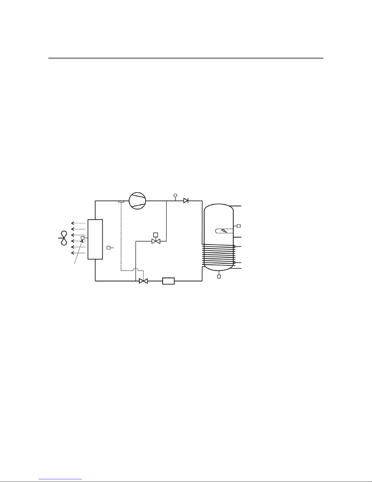
3.4 Operation of the NIBE MT-WH 2029-F/1FS
The control starts the compressor when hot water is needed. The compressor operates until the
water in the water tank reaches the set temperature. Usually, the NIBE MT-WH 2029-F/1FS can
produce enough hot water to cover the need of a household of 4 persons.
If the NIBE MT-WH 2029-F/1FS is not able to produce enough domestic hot water, an electrical
immersion heater integrated in the water tank can be activated.This way more domestic hot
water can be produced. It is possible to set the temperature to which the electrical immersion
heater should heat the water. The electrical immersion heater should only be used when there is
a need, as it consumes significantly more energy that the compressor.
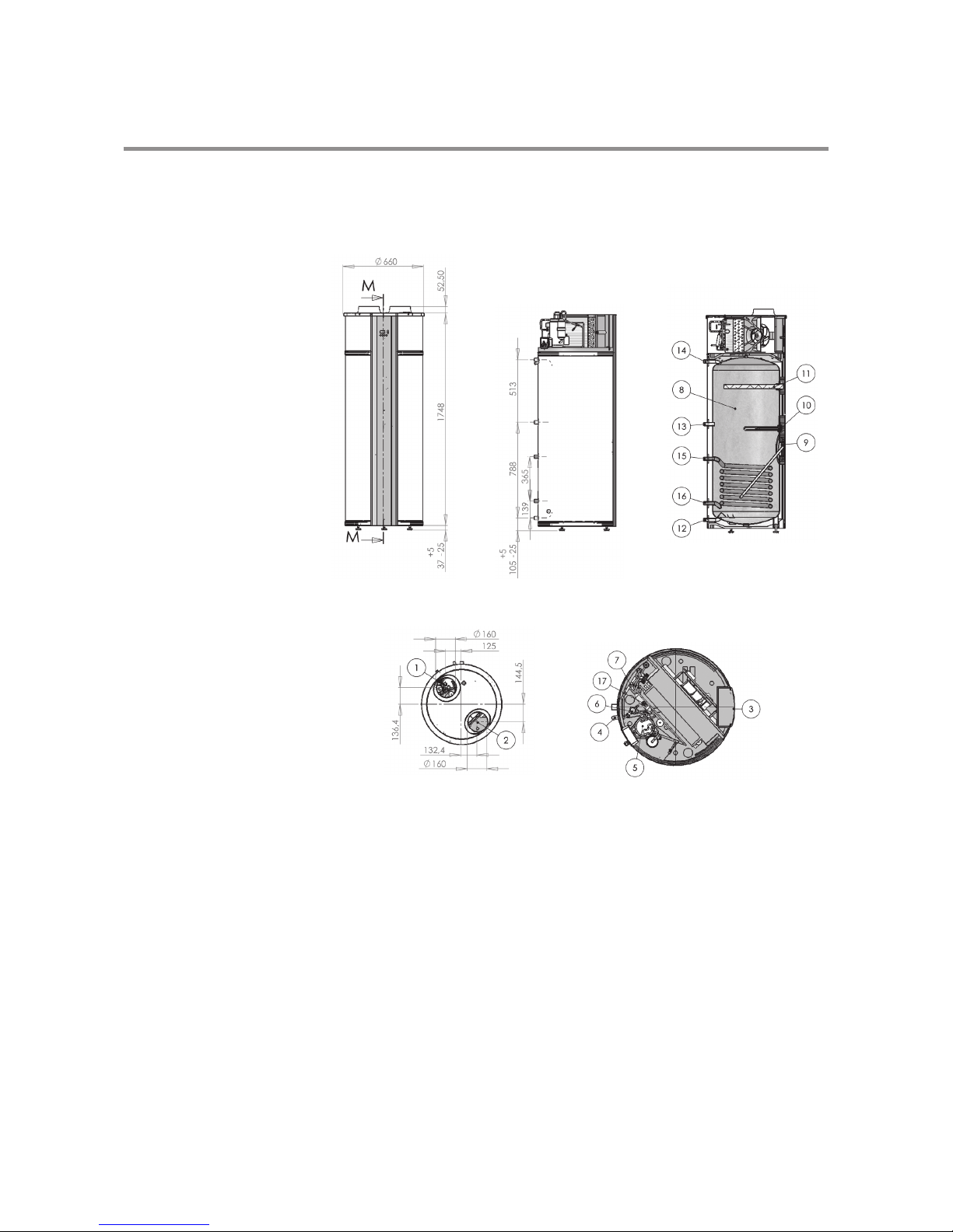
3.5 Technical data
Domestic hot water heat pump NIBE MT-WH 2029-F/1FS
Diameter without pipe connections mm Ø660
Height mm 1837
Weight without water, F/1FS kg 120/126
Electrical connections V/Hz 230/50 (L1, N, G)
Fuse size A13 (10)
Refrigerant / quantity -/kg R134a /1.1
Ingress Protection rating -IP 21
Electrical immersion heater (supplementary heat) kW 1.5
Any work carried out on
this unit must only be done by
skilled personnel.
Take all necessary precautions to
avoid accidents.