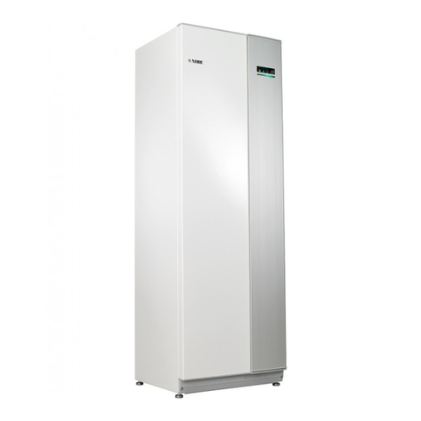
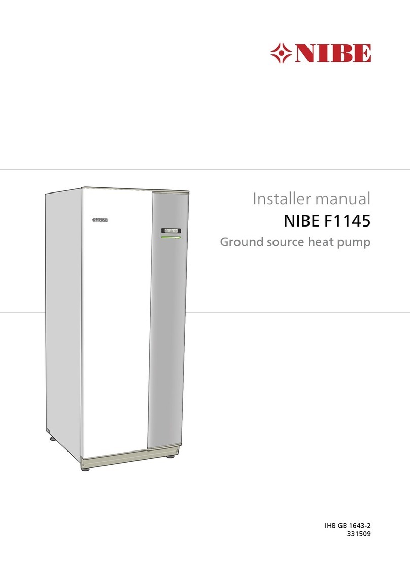
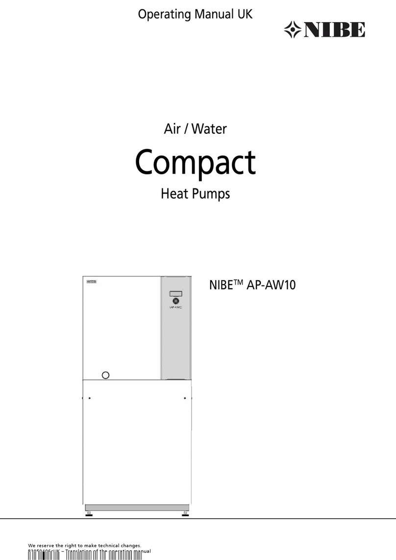
Nibe FIGHTER 310P Technical specifications

INSTALLATION AND MAINTENANCE INSTRUCTION
FIGHTER 310P
230V
MOS GB 0850-4
FIGHTER 310P
511350
LEK
Fighter310P
Fighter310P

LEK
LEK
LEK
LEK
1
3
4
5
2
LEK
LEK
LEK
LEK
1
3
4
5
2

Contents 1
FIGHTER 310P
General points for the installation engineer
Transport and storage ......................................... 11
Handling .............................................................. 11
Erecting the heat pump ....................................... 11
Maximum boiler and radiator volumes ................. 11
Lifting straps ........................................................ 11
Hard water areas ................................................. 11
Inspection of the installation ................................ 11
Temperatures in FIGHTER 310P ......................... 11
Pipe connections
General ................................................................ 12
Tap water connection ........................................... 13
Expansion vessel, tap water ................................ 13
Pump and pressure drop diagrams ..................... 13
Ventilation connection
Ventilation flow ..................................................... 14
Kitchen duct ......................................................... 14
Adjustment .......................................................... 14
Duct installation ................................................... 14
Fan diagram ......................................................... 14
Electrical connections
Connection .......................................................... 15
Power rating as set at the factory ........................ 15
Resetting the temperature limiter ........................ 15
Max current ......................................................... 15
Immersion heater ................................................ 15
Setting the fan capacity ...................................... 16
Blocking immersion heater operation ................. 16
Connecting the outside sensor ............................ 17
Centralised load control and load monitor .......... 17
Commissioning and adjusting
Preparations ........................................................ 18
Filling the water heater and the heating system
... 18
Venting the heating system ................................. 18
Starting ................................................................ 18
Setting the ventilation .......................................... 19
Readjustment ...................................................... 19
Draining of the heating system ............................ 19
Emptying the water heater ................................... 19
Cleaning the system / Flushing out of the
hot water and central heating system ............... 19
Setting the automatic heating control system
Heating curve offset -2 ........................................ 20
Heating curve offset 0 ......................................... 20
Heating curve offset +2 ....................................... 20
Setting using diagrams ........................................ 20
Dealing with malfunctions
Low temperature or a lack of hot water ............... 21
Low or a lack of ventilation .................................. 21
Low room temperature ........................................ 21
High room temperature ........................................ 21
Power switch position “ ”................................ 21
Cleaning the fan .................................................. 21
Indications on the display .................................... 22
Resetting pressostats .......................................... 22
Resetting the miniature circuit breakers .............. 23
High extract air temperature ............................... 23
Helping the circulation pump to start ................... 23
Service
Opening the front panel ....................................... 24
Refrigerant system .............................................. 24
Channel description ............................................. 24
Electrical circuit diagram
Electrical circuit diagram ...................................... 25
Changing the output ............................................ 25
Component locations
Component locations ........................................... 26
List of components
List of components .............................................. 27
Dimensions
Dimensions and setting-out coordinates ............. 28
Measuring principle ............................................. 28
Technical specifications
Technical specifications ....................................... 29
Accessories
Accessories ......................................................... 30
Enclosed kit ......................................................... 30
General
Concise product description ................................ 2
Setting table ......................................................... 2
System description
Principle of operation ........................................... 3
System diagram ................................................... 3
Front panel
Upper (visible) part of the front panel .................. 4
Visible functions ................................................... 5
Lower (hidden) part of the front panel ................. 6
Hidden functions .................................................. 7
Room temperature
Automatic heating control system ........................ 8
Default setting....................................................... 8
Changing the room temperature .......................... 8
Maintenance routines
Cleaning the air filter ........................................... 9
Cleaning the ventilation devices .......................... 9
Checking the safety valves .................................. 10
Pressure gauge ................................................... 10
Extract air temperature ........................................ 10
For Home Owners
For the Installation engineer

General
FIGHTER 310P
For Home Owners
2
In order to get the ultimate benefit from your heat pump FIGHTER 310P you should read
through the For Home Owners section in this Installation and Maintenance Instruction.
FIGHTER 310P is an exhaust air heat pump. This means that it collects the energy in the
ventilation air and uses it for hot water and room heating.
A microprocessor ensures that the heat pump always works efficiently.
FIGHTER 310P is a Swedish-made quality product which will last a long time and run reli-
ably without unpleasant surprises.
For the installation engineer: Please, hand over to the home owner his manual after final-
ised installation.
To be filled in when the heat pump has been installed
This appliance is not intended for use by persons (including children) with reduced
physical, sensory or mental capabilities, or lack of experience and knowledge, unless
they have been given supervision or instruction concerning use of the appliance by a
person responsible for their safety.
Children should be supervised to ensure that they do not play with the appliance.
Rights to make any design or technical modifications are reserved.
Manufacter:
NIBE AB
Box 14
Järnvägsgatan 40
285 21 MARKARYD
SWEDEN
Maxiumum water
supply pressure 16 bar
Immersion heater R50 / 8000W /
230 V
Operating pressure, tap
water 6 bar
Expansion vessel, tap
water, charge pressure 3,5 bar
Expansion vessel,
heating water,
charge pressure
0,5 bar
Pressure reduction valve,
setting 3,5 bar
Volume, water heater 170 litres
Mass, unit, filled with
water 435 kg
Maximum primary
working
pressure (heating side)
2,5 bar
Set opening pressure of
temperature and
pressure valve
7 bar
Set opening pressure
relief valve 6 bar
Set opening, temerature
limiter,
immersion heater
88 °C
Set opening, temerature
limiter,
compressor
88 °C
Heating up time from
15 °C to stop
temperature for
compressor
7 h 8 min
Re-heating time, 70 % of
total volume (only
compressor working)
4 h 50 min
The serial number (103), should always be stated with all
correspondence with NIBE.
______________
Installation date
Installer
Pre-pressure in the expansion vessel (0.5 bar on delivery)
Chosen output, immersion heater
Circulation pump setting
Setting, trim valve
Fan rating
Switch Selected position on
terminal block (22)
for this cable
(1 – 10)
Measured total
exhaust air flow
Position A (reduced) White cable 095
Position B (normal) White cable 097
Position C (forced) White cable 099
Setting damper (where applicable)
Setting Heating curve selection
Setting Offset heating curve
Date___________ Signed__________________________________
l/s m3/h

FIGHTER 310P comprises an electric boiler with a
copper lined water heater and a heat pump which
recovers energy from the ventilation air. The recovered
energy is supplied to the heat pump. The heat pump
must be installed in a ventilation system intended for
mechanical exhaust air.
The output of the immersion heater is max 8.0 kW
(Supplied output of 6.0 kW).
When the exhaust air at room temperature passes
through the evaporator, the refrigerant evaporates
because of its low boiling point. In this way the heat in
the room air is transferred to the refrigerant.
The refrigerant is then compressed in a compressor,
causing the temperature to rise considerably.
The warm refrigerant is fed to the condenser, which is
in the boiler water. Here the refrigerant gives off its
heat to the boiler water, so that its temperature drops
and the refrigerant changes state from gas to liquid.
The refrigerant then goes via filters to the expansion
valve, where the pressure and temperature are further
reduced.
The refrigerant has now completed its circulation and
returns to the evaporator.
System description
FrånluftAvluft
FrånluftAvluft PoistoilmaKierrätetty ilma Frånluft
Avluft
Förångare
Expansionsventil
Kompressor
Frånluftsfläkt
Kondensor
Elpatron
Frånluft
Avluft
Förångare
Expansionsventil
Kompressor
Frånluftsfläkt
Kondensor
Elpatron
Frånluft
Avluft
Frånluft
Avluft
Förångare
Expansionsventil
Kompressor
Frånluftsfläkt
Kondensor
Elpatron
Avkastluften
Avløpsluften
Till F 310P/360P UK 1-fas Till F 310P/360P UK 1-fas
Frånluft
Avluft
Det är denna som används i MOSen.
3
For Home Owners
FIGHTER 310P
LEK
C
When the room air has
passed through the heat
pump it is discharged. The
temperature of the air has
been significantly reduced
as the heat pump has
extracted the energy in the
room air.
G
The air from the kitchen
fan goes directly out into
a separate duct.
B
The warm room
air is fed to
FIGHTER 310P
D
FIGHTER 310P supplies
the house with both hot
water and room heating. E
Outdoor air is drawn into the house.
A
The warm room air is
drawn into the air duct
system.
F
Air is transported
from rooms with
outdoor air devices to
rooms with exhaust
air devices.
Principle of operation
System diagram
Extract air Exhaust air

Front panel
FIGHTER 310P
For Home Owners
4
Upper (visible) part of the front panel
Display screen
Art.nr . 611603
2
1bar 3
04
2
1bar 3
04
2
1bar 3
04
T r ansparent, blåfärgad film (ej hål).
18,6
98,1
26,3
4,2
86,3
92,7
126,8
129,8
132,8
145,2
272,5
336
41
19,2
83
90.5
111
98,6
523
10,5
Ø 52,8
53,5
135,3
130,7
15
70,5
135,3
261,5
r=4,5
37
23
9
2 st Ø 4,5, transparent, ofärgad film (ej hål).
OBS! Endast halv cirkel (radie=11)
Slits på baksidan
De 8 grårastrerade ytorna (Ø22)
skall ej förses med häftämne.
49,5
84,4
85,7
186,3
196,8
42,5
67,5
57,25
52
161
Ø 13
Ø 18,5
Ø 62
Hål 16 x 31
Hål 16 x 16
313,2
2 st urstansninga , bredd=5 och r=2,5
SwitchPressure gauge Indicator lamps
Extra hot water Heating curve offset
A DCB
E F

Front panel 5
For Home Owners
FIGHTER 310P
Pressure gauge
Here the radiator circuit pressure is displayed.
Gauge graduation is 0 - 4 bar. Normal pressure
is 0.5 - 1.5 bar.
Upper lamp
Lit Compressor is operational.
Flashing –
Not lit Compressor is not operational.
Centre lamp
Lit Automatic defrosting.
Flashing –
Not lit Normal mode.
Lower lamp
Lit Immersion heater is operational.
Flashing Parts of the immersion heater are
disabled by an external controller
(load monitor, etc).
Not lit Immersion heater is not operational.
Numerical display
In normal mode the boiler temperature is dis-
played here. The two digits on the left indicate
the “channel number” and the two on the right
the reading/setting of that channel.
In the event of a malfunction, an error message
is displayed alternately with channel number
and value. See “Dealing with malfunctions” —
“Indications on the numerical display”.
NOTE! When switching from Standby mode “
” to normal mode “1” the numerical display
can remain dimmed for a brief period. This
can also occur at extremely low outdoor tem-
peratures.
Extra hot water
Pressing the “Extra hot water” button raises the
boiler temperature to about 60 °C, giving
increased water capacity for about 24 hours. In
this mode, the built-in lamp is constantly lit.
Pressing the button again gives a permanent
function which raises temperature of the hot
water during 6 hours / day. In this mode, the
built-in lamp flashes.
Pressing the button again resets the above
functions.
Heating curve offset
With the “Heating curve offset” button you can
change the offset of the heating curve and thus
the room temperature.
E
A
B
C
D
F
Art.nr. 611822
2
1bar 3
04
2
1bar 3
04
2
1bar 3
04
Transparent, blåfärgad film (ej hål).
67,5
57.25
26,3
86,3
92,7
126,8
129,8
132,8
145,2
336
41
19,2
83
90.5
111
98,6
523
10,5
Ø 52,8
53,5
135,3
130,7
15
70,5
135,3
r=4,5
37
23
9
2 st Ø 4,5, transparent, ofärgad film (ej hål).
OBS! Endast halv cirkel (radie=11)
Slits på baksidan
De 8 grårastrerade ytorna (Ø22)
skall ej förses med häftämne.
49,5
84,4
85,7
186,3
196,8
42,5
52
161
Ø 13
Ø 18,5
Hål 16 x 31
Hål 16 x 16
313,2
Power switch
with 3 modes 0 - 1 - :
0 Heat pump off.
1Normal mode. All control functions connect-
ed.
Standby. This mode is used during start up
and with any operating disruptions.
Indicator lamps
Visible functions

Front panel
FIGHTER 310P
For Home Owners
6
Lower (hidden) part of the front panel
Art.nr . 611603
2
1bar 3
04
2
1bar 3
04
2
1bar 3
04
T r ansparent, blåfärgad film (ej hål).
18,6
98,1
26,3
4,2
86,3
92,7
126,8
129,8
132,8
145,2
272,5
336
41
19,2
83
90.5
111
98,6
523
10,5
Ø 52,8
53,5
135,3
130,7
15
70,5
135,3
261,5
r=4,5
37
23
9
2 st Ø 4,5, transparent, ofärgad film (ej hål).
OBS! Endast halv cirkel (radie=11)
Slits på baksidan
De 8 grårastrerade ytorna (Ø22)
skall ej förses med häftämne.
49,5
84,4
85,7
186,3
196,8
42,5
67,5
57,25
52
161
Ø 13
Ø 18,5
Ø 62
Hål 16 x 31
Hål 16 x 16
313,2
2 st urstansninga , bredd=5 och r=2,5
Indicator
lamps Heating
curve selection
Operating
mode Channel
selection
I
HJ
G
L
Miniature circuit-breaker Temperature limiter
K
Fan speed
M L

Front panel 7
FIGHTER 310P
For Home Owners
Channel selection
Use the “Channel selection” button to browse
forward through the display window channels to
see the required reading or setting.
Available readings/settings include:
1Boiler temperature
2Flow temperature
3Outdoor temperature
5Extract air temperature
Normally the display always shows Channel 1.
When you have browsed through the channels,
channel 1returns after a while.
Heating curve selection
Use the “Heating curve selection” knob to set
the automatic heating control system; see sec-
tion “Room temperature”.
I
J
Hidden functions
The two lamps next to the operating mode selec-
tor indicate the chosen operating mode. This
should not be confused with the indicating lamps
in the numerical display.
Uppermost lamp “Immersion heater”
Lit The immersion heater may be con-
nected if necessary, i.e. when the
compressor cannot single handed
cover the heating requirement.
Not lit The immersion heater is disabled.
Bottom lamp “Circulation pump”
Lit The circulation pump is
operational.
Not lit The circulation pump is not opera-
tional, however it is automatically
exercised twice a day. The shunt is
valve is also closed in this position.
Operating mode indications
G
Art.nr. 611822
2
1bar 3
04
2
1bar 3
04
2
1bar 3
04
Transparent, blåfärgad film (ej hål).
67,5
57.25
26,3
86,3
92,7
126,8
129,8
132,8
145,2
336
41
19,2
83
90.5
111
98,6
523
10,5
Ø 52,8
53,5
135,3
130,7
15
70,5
135,3
r=4,5
37
23
9
2 st Ø 4,5, transparent, ofärgad film (ej hål).
OBS! Endast halv cirkel (radie=11)
Slits på baksidan
De 8 grårastrerade ytorna (Ø22)
skall ej förses med häftämne.
49,5
84,4
85,7
186,3
196,8
42,5
52
161
Ø 13
Ø 18,5
Hål 16 x 31
Hål 16 x 16
313,2
Operating mode
When the heat pump is started, all functions
(immersion heater, circulation pump and auto-
matic heating control system) are running.
Pressing the “Operating mode” button once dis-
ables the immersion heater.
Pressing it once more stops the circulation
pump as well. Only hot water production is then
obtained.
Pressing it yet again reconnects the immersion
heater and the circulation pump.
H
Miniature circuit-breaker
Resetting the miniature circuit
breakers.
K
Temperature limiter
Resetting the temperature limiter.
L
Art.nr. 611822
2
1bar 3
04
2
1bar 3
04
2
1bar 3
04
Transparent, blåfärgad film (ej hål).
67,5
57.25
26,3
86,3
92,7
126,8
129,8
132,8
145,2
336
41
19,2
83
90.5
111
98,6
523
10,5
Ø 52,8
53,5
135,3
130,7
15
70,5
135,3
r=4,5
37
23
9
2 st Ø 4,5, transparent, ofärgad film (ej hål).
OBS! Endast halv cirkel (radie=11)
Slits på baksidan
De 8 grårastrerade ytorna (Ø22)
skall ej förses med häftämne.
49,5
84,4
85,7
186,3
196,8
42,5
52
161
Ø 13
Ø 18,5
Hål 16 x 31
Hål 16 x 16
313,2
Fan speed
This switch is used for changing the fan
speed.
It is possible to switch between three different
speeds:
Position A: Reduced ventilation
Position B: Normal ventilation
Position C: Forced ventilation
Position B is normally used.
Position A is used on occasions when a lower
ventilation flow is acceptable in the house, for
example, when no one is in the house. This
position should not be used over long periods.
Otherwise there is a risk of an inferior indoor cli-
mate as well as damage due to dampness in
the house.
Position C is used on occasions when a higher
ventilation flow is sought in the house, for exam-
ple, when there are many people in the house.
This position should not be used over long peri-
ods. Otherwise this will increase energy con-
sumption and with that operating costs.
M
Art.nr. 611603
2
1bar 3
04
2
1bar 3
04
2
1bar 3
04
Tr ansparent, blåfärgad film (ej hål).
18,6
98,1
26,3
4,2
86,3
92,7
126,8
129,8
132,8
145,2
272,5
336
41
19,2
83
90.5
111
98,6
523
10,5
Ø 52,8
53,5
135,3
130,7
15
70,5
135,3
261,5
r=4,5
37
23
9
2 st Ø 4,5, transparent, ofärgad film (ej hål).
OBS! Endast halv cirkel (radie=11)
Slits på baksidan
De 8 grårastrerade ytorna (Ø22)
skall ej förses med häftämne.
49,5
84,4
85,7
186,3
196,8
42,5
67,5
57,25
52
161
Ø 13
Ø 18,5
Ø 62
Hål 16 x 31
Hål 16 x 16
313,2
2 st urstansninga , bredd=5 och r=2,5

Room temperature
FIGHTER 310P
For Home Owners
8
The indoor temperature depends on several factors.
During the hot season, solar radiation and heat given
off by people and equipment are sufficient to keep the
house warm. When it gets colder outside, the heating
system must be started. The colder its gets, the hotter
the radiators must be.
This adjustment is made automatically, however the
basic settings must first be made on the boiler, see the
section “Room temperature” “Default setting”.
The basic heating is set with the “Heating curve selec-
tion” knob and with the “Heating curve offset” knob.
If you do not know the correct settings use the basic
data from the map opposite.
If the required room temperature is not obtained, read-
justment may be necessary.
NOTE! Wait one day between settings so that the tem-
peratures have time to stabilise.
Readjustment of basic settings.
Cold weather conditions
If the room temperature is low, increase the heating
curve selection setting by one step.
If the room temperature is high, reduce the heating
curve selection setting by one step.
Warm weather conditions
If the room temperature is low, increase the heating
curve offset setting by one step.
If the room temperature is high, reduce the heating
curve offset setting by one step.
Changing the room temperature manually.
If you want to temporarily or permanently lower or
raise the indoor temperature relative to the previously
set temperature, turn the
“Heating curve offset” knob
anticlockwise or clockwise respectively. One scale mark-
ing corresponds to a change of about one degree in the
room temperature.
NOTE! An increase in the room temperature may be
inhibited by the radiator or floor heating thermostats, if
so these must be turned up.
Default setting
Automatic heating control system
Changing the room
temperature
Art.nr. 611822
2
1
bar
3
04
2
1
bar
3
04
2
1
bar
3
04
Transparent, blåfärgad film (ej hål).
67,5
57.25
26,3
86,3
92,7
126,8
129,8
132,8
145,2
336
41
19,2
83
90.5
111
98,6
523
10,5
Ø 52,8
53,5
135,3
130,7
15
70,5
135,3
r=4,5
37
23
9
2 st Ø 4,5, transparent, ofärgad film (ej hål).
OBS! Endast halv cirkel (radie=11)
Slits på baksidan
De 8 grårastrerade ytorna (Ø22)
skall ej förses med häftämne.
49,5
84,4
85,7
186,3
196,8
42,5
52
161
Ø 13
Ø 18,5
Hål 16 x 31
Hål 16 x 16
313,2
Heating curve
selection
Heating curve
offset

The heat pump's air filter (63) needs to be cleaned
regularly (approximately 4 times per year) by pulling it
out and shaking it clean.
■Set the switch (8) to “0”.
■Open the upper front cover by pulling it out by the
lower edge, then lifting it up.
■Pull out the filter holder (78).
■Take out the filter and shake off any dirt.
Check that the filter is not damaged. New original
filters can be ordered from NIBE.
■ Assembly takes place in the reverse order.
The interval between cleaning operations varies and
depends on the amount of dust in the exhaust air.
Every third month a reminder for cleaning the filter is
shown in the display as “A-01”. Note that the time will
be set to zero by setting the switch to "0".
Maintenance routines 9
For Home Owners
LEK
The heat pump and its ventilation ducting require some
regular maintenance when the following points should
be checked.
The numbers in brackets refer to the section “Compo-
nent locations”.
Cleaning the air filter
Art.nr. 611822
2
1
bar
3
04
2
1
bar
3
04
2
1
bar
3
04
Transparent, blåfärgad film (ej hål).
67,5
57.25
26,3
86,3
92,7
126,8
129,8
132,8
145,2
336
41
19,2
83
90.5
111
98,6
523
10,5
Ø 52,8
53,5
135,3
130,7
15
70,5
135,3
r=4,5
37
23
9
2 st Ø 4,5, transparent, ofärgad film (ej hål).
OBS! Endast halv cirkel (radie=11)
Slits på baksidan
De 8 grårastrerade ytorna (Ø22)
skall ej förses med häftämne.
49,5
84,4
85,7
186,3
196,8
42,5
52
161
Ø 13
Ø 18,5
Hål 16 x 31
Hål 16 x 16
313,2
The building’s ventilation devices should be cleaned
regularly with a small brush to keep the correct venti-
lation.
The device settings must not be changed.
NOTE! If you take down more than one ventilation
device for cleaning, do not mix them up.
Check that the ventilation opening (84) behind the
lower front cover is not blocked. Clean if necessary.
FIGHTER 310P
Cleaning the ventilation devices
Warning to the
user!
Do not remove or adjust any
component part of this unvented water
heater: Contact the installer.
Warning to the
user!
If this unvented water heater develops
a fault, such as a flow of hot water
from the discharge pipe, switch the
heater off and contact the installer.

Maintenance routines
FIGHTER 310P
For Home Owners
10
k.v.
v
.v.
2
1bar 3
04
LEK
k.v.
v
.v.
2
1bar 3
04
LEK
LEK
Check that the temperature of the extract air (channels
5) is clearly lower than the room temperature when the
compressor is operational, also see section “Dealing
with malfunctions” ”High extract air temperature”. It is
normal that the extract air temperature varies.
The pressure gauge reading should be between the
initial pressure of the expansion vessel (normally 0.5
bar) and 2.5 bar (25 mvp). See “Commissioning and
adjusting”
Pressure gauge
Extract air temperature
Art.nr. 611822
2
1bar 3
04
2
1bar 3
04
2
1bar 3
04
Transparent, blåfärgad film (ej hål).
67,5
57.25
26,3
86,3
92,7
126,8
129,8
132,8
145,2
336
41
19,2
83
90.5
111
98,6
523
10,5
Ø 52,8
53,5
135,3
130,7
15
70,5
135,3
r=4,5
37
23
9
2 st Ø 4,5, transparent, ofärgad film (ej hål).
OBS! Endast halv cirkel (radie=11)
Slits på baksidan
De 8 grårastrerade ytorna (Ø22)
skall ej förses med häftämne.
49,5
84,4
85,7
186,3
196,8
42,5
52
161
Ø 13
Ø 18,5
Hål 16 x 31
Hål 16 x 16
313,2
Checking the safety valves
LEK
Art.nr. 611822
2
1bar 3
04
2
1bar 3
04
2
1bar 3
04
Transparent, blåfärgad film (ej hål).
67,5
57.25
26,3
86,3
92,7
126,8
129,8
132,8
145,2
336
41
19,2
83
90.5
111
98,6
523
10,5
Ø 52,8
53,5
135,3
130,7
15
70,5
135,3
r=4,5
37
23
9
2 st Ø 4,5, transparent, ofärgad film (ej hål).
OBS! Endast halv cirkel (radie=11)
Slits på baksidan
De 8 grårastrerade ytorna (Ø22)
skall ej förses med häftämne.
49,5
84,4
85,7
186,3
196,8
42,5
52
161
Ø 13
Ø 18,5
Hål 16 x 31
Hål 16 x 16
313,2
FIGHTER 310P has three safety valves, one for the
heating system and two for the water heater.
The safety valves must be checked regularly. Check
one valve at a time as follows:
■Open the valve.
■Check that water flows through the valve.
■Close the valve.
■The heating system may need to be refilled after
checking the safety valve (52), see the section
”Commissioning and adjustment” – ”Filling the
heating system”.
52
47
LEK
k.v.
v
.v.
2
1bar 3
04
LEK
145
LEK
LEK

General points for the installation engineer 11
For the Installer
FIGHTER 310P
Current regulations require the heating installation to
be inspected before it is commissioned. The inspec-
tion must be carried out by a suitably qualified person.
The above applies to installations with a closed expan-
sion vessel. A new inspection must be made when
changing the heat pump or the expansion vessel.
The heat pump should be transported and stored ver-
tically in the dry.
The heat pump contains highly inflammable
refrigerant. Special care should be exercised
during handling, installation, service, clean-
ing and scrapping to avoid damage to the
refrigerant system and in doing so reduce
the risk of leakage.
Transport and storage
Handling
The lifting straps on top of the heat pump should be
removed before starting as these can otherwise cause
increased sound levels. These are removed by first
cutting with a knife and then pulling them out.
Lifting straps
Inspection of the installation
The volume of the expansion vessel
(85) is 12 litres and it is pressurised as
standard to 0.5 bar (5 mvp). As a
result, the maximum permitted height
“H” between the vessel and the high-
est radiator is 5 metres; see figure.
If the standard initial pressure in the
pressure vessel is not high enough it
can be increased by adding air via the
valve in the expansion vessel. The initial pressure of
the expansion vessel must be stated in the inspection
document.
Any change in the initial pressure affects the ability of
the expansion vessel to handle the expansion of the
water.
The maximum system volume excluding the boiler is
285 litres at the above initial pressure.
Maximum boiler and radiator
volumes
H
Normal temperature levels in boiler or water heat-
er.
The temperature of the hot water in the water heater
may vary between about 50 and 60 °C.
The “Extra hot water” knob (18) on the front panel is
used to increase the hot water capacity.
Temperatures in FIGHTER 310P
NOTE!
The transport guard around the compressor
must be removed before starting.
Temperatur
Utetemperatur
F
r
a
m
l
e
d
n
i
n
g
s
t
e
m
p
e
r
a
t
u
r
Min begränsning
20
20 Sommar Vinter DUT
DUT: Dimensionerande utetemperatur
60
°C
°C
Vattenvattentemperatur "Normalfall"
Panntemperatur
50
40
30
Vattenvattentemperatur "Extra varmvatten"
Temperatuur
Välistemperatuur
P
e
a
l
e
v
o
o
l
u
t
e
m
p
e
r
a
t
u
u
r
Min. piirang
20
20 Suvi Talv DUT
DUT: Dimensiooneritud
60
°C
°C
Veeboileri temperatuur "Normaaljuhus"
Katlatemperatuur
50
40
30
Veeboileri temperatuur"Lisa soe vesi"
Temperatur
Udetemperatur
F
r
e
m
l
ø
b
s
t
e
m
p
e
r
a
t
u
r
Min. begrænsning
20
20 Sommer Vinter DUT
DUT: Dimensionerende udetemperatur
60
°C
°C
Vandvarmertemperatur “Normale forhold”
Kedeltemperatur
50
40
30
Vandvarmertemperatur “Ekstra varmt vand”
Temperatur
Außentemperatur
V
o
r
l
a
u
f
t
e
m
p
e
r
a
t
u
r
Unterer Grenzwert
20
20 Sommer Winter DUT
60
°C
°C
Warmwasserspeichertemperatur "Normalbetrieb"
Heizkesseltemperatur
50
40
30
Warmwasserspeichertemperatur "Extra Warmwasser"
DUT: Norm-Temperatur
Temperature
Outside
temperature
F
l
o
w
t
e
m
p
e
r
a
t
u
r
e
Min. limit
20
20 Summer Winter DUT
DUT: Design basis outside temperature
60
°C
°C
Hot watertemperature "Normal"
Boiler temperature
50
40
30
Hot water temperature "Extra hot water"
Temperatur
Außentemperatur
V
o
r
l
a
u
f
t
e
m
p
e
r
a
t
u
r
Unterer Grenzwert
20
20 Sommer Winter DUT
DUT: Norm-Temperatur
60
°C
°C
Warmwasserspeichertemperatur "Normalbetrieb"
Heizkesseltemperatur
50
40
30
Warmwasserspeichertemperatur "Extra Warmwasser"
Temperatūra
Išorės temperatūra
I
š
e
i
n
a
n
t
i
t
e
m
p
e
r
a
t
ū
r
a
Žemiausia riba
20
20 Vasara Žiema DUT
60
°C
°C
Karšto vandens rezervuaro temperatūra "Normalus funkcionavimas"
Šildymo katilo temperatūra
50
40
30
Karšto vandens rezervuaro temperatūra "Specialus karštas vanduo"
DUT: Normali temperatūra
LT
EST
LEK
12
The heat pump should preferably be erected with its
back about 10 mm from an outside wall in a utility room
or similar, to minimise noise nuisance. If this is not
possible, avoid placing it against a wall behind a bed-
room or other room where noise may be a problem.
Irrespective of the placement the wall should be sound
insulated. NOTE! The distance between the heat pump
and the wall should be at least 10 mm.
Route pipes so they are not fixed to an internal wall
that backs on to a bedroom or living room.
An area of approximately 15 cm is required on the left
side of the heat pump, at the temperature and pres-
sure valve (145) to enable access to the valve.
NOTE! Since a waterfilled FIGHTER 310P weighs
roughly 435 kilos, the floor must stand such a weight.
Erecting the heat pump Normally it is no problem to install FIGHTER 310P in
hard water areas since the maxing working tempera-
ture is 65 °C.
Hard water areas

Pipe connections
FIGHTER 310P
For the Installer
12
If the vertical distance, 300 mm, is hard to fulfil a heigh-
tening console is available as an accessorie. No valve
should be fitted between the pressure reduction valve
(expansion valve) and the storage cylinder.
500 mm maximum
300 mm
minimum
Tundish
Metal discharge pipe from
temperature relief value to tundish.
Metal discharge pipe from tundish,
with continous fall.
Discharge below
fixed grating.
Fixed grating
Trapped gulley
Possible wall
Safety device
(e.g. temperature
relief valve).
Table sizing of copper discharge pipe for common temperature relief valve outlet sizes.
Pipe installation must be carried out in accordance with
current norms and directives.
The system requires a low-temperature dimensioning of
the radiator circuit. At DUT, the highest recommended
temperatures are 55 °C on the flow line and 45 °C on
the return line.
When the circulation pump is running, the flow in the
radiator circuit must not be completely stopped.
The total volume is 240 litres, with 170 litres in the water
heater and 70 litres in the boiler section.
The pressure vessel in the FIGHTER 310P is approved
for max 9.0 bar (0.9 MPa) in the water heater and
2.5 bar (0.25 MPa) in the double shell section.
Overflow water from the evaporator collection tray and
safety valves goes via non-pressurised collecting pipes
to a drain so that hot water splashes cannot cause inju-
ry. These non-pressurised collecting pipes shall not be
used for anything else. A discharge pipe from the tundish
(108) connected to the expansion relief valve (47) (safe-
ty valve) shall also be connected to a drain in the same
way.
Discharge pipes from tundishes shall have av vertical
section of pipe at least 300 mm long, before any elbows
or bends in the pipework. See following picture.
General
Valve
outlet
size
Minimum size
of discharge
pipe
Minimum size of discharge
pipe from tundish
Maximum resistance allo-
wed, expressed as a len-
ght of straight pipe (i.e. no
elbows or bends)
Resistance created
by each elbow or
bend
G 1/2 15 mm 22 mm up to 9 m 0,8 m
G 1/2 15 mm 28 mm up to 18 m 1,0 m
G 1/2 15 mm 35 mm up to 27 m 1,4 m
<G3> / 4 22 mm 28 mm up to 9 m 1,0 m
<G3> / 4 22 mm 35 mm up to 18 m 1,4 m
<G3> / 4 22 mm 42 mm up to 27 m 1,7 m
G 1 28 mm 35 mm up to 9 m 1,4 m
G 1 28 mm 42 mm up to 18 m 1,7 m
G 1 28 mm 54 mm up to 27 m 2,3 m

Pipe connections 13
For the Installer
FIGHTER 310P
The enclosed expansion vessel (106) for tap water
shall be installed in the tap water circuit after the pres-
sure reduction valve.
Expansion vessel, tap water
Pump and pressure drop diagrams
Pumpkapacitet
Flöde
Tillgängligt tryck, kPa
Internt tryckfall i panna
(inklusive armatur)
Tillgänglig pumpkapacitet
(pannans interntryckfall fråndraget)
3
2
1
0 500 1000
0
1500 2000
4
l/h
P
5
6
Interner Druckverlust in der Heizung
(einschließlich Armatur)
Zugängliche Pumpenkapazität
(interner Heizdruckverlust abgezogen)
3
2
1
kPa
kPa
60
50
40
30
20
10
0
mWs
l/s
0,50,40,30,20,10
Höchstmenge:1700 l/h
3
2
1
0 500 1000
0
1500 2000
4
l/h
l/h
l/h
P
5
6
Internal pressure drop in boiler
(including fittings)
Available pump capacity
(less the internal pressure drop of the boiler)
3
2
1
wg
10
200
0
0
20
400
30
600
40
800
50
1000
60
1200
70
1400 1600 1800 2000
50
40
30
20
10
0
m
Flow
l/s
0,50,40,30,20,10
l/s
0,50,40,30,20,10
Max flow: 1700 l/h Max flow: 1700 l/h
Max flöde: 1700 l/h
l/s
0,50,40,30,20,10
Flow, l/h
Available pump capacity, kPa
10
200
0
0
20
400
30
600
40
800
50
1000
60
1200
70
1400 1600 1800 2000
Menge
Vorhandener Druck, kPa
10
200
0
0
20
400
30
600
40
800
50
1000
60
1200
70
1400 1600 1800 2000
Max flow
1700 l/h
Available pressure, kPA
Flow
Warning to the
installer!
This installation is subject to building
regulation approval, notify the Local
Authority of intention to install.
Warning to the
installer!
Use only manufacturer’s
recommended replacement parts.
Tap water connection
Hot and cold water are connected to pos (74) (hot
water) and (73) (cold water).
The attendant expansion vessel (107) must be con-
nected to the hot water system.
The heat pump should be supplemented with an elec-
tric water heater if a bubble pool or other significant
consumer of hot water is installed.
If the heater is equipped with a valve connection Ø of
15 mm, this should be replaced with an equivalent
(split) Ø 22 mm coupling.
Appropriate heaters are COMPACT 100-300 for floor-
mounting and EMINENT 35-100 for wall-mounting.
1. Split the valve coupling.
2. Attach the valve coupling section to the heater’s
incoming cold water.
3. Attach the mixing valve section to the heater’s out-
going hot water.
4. Plug the split on the valve coupling section.
LK 550/506/513 LK 545/506/513
LK 545/508/518 MMA MMA/LK 518 SYR
LK 506
LK 501
SOLE
LK 545/508/514 LK 545/508/514
utan vakuumventil
LK 550/Cu-rör/506//513 LK 540/512
LEK
LEK
LEK
LEK
LEK
LEK
0,9
MPa
LEK
LEK
LEK
LEK
LK 560/514
ARMATUR
LEK
LEK
LEK
ARMATUR
LEK
ARMATUR
Valve coupling section Mixing valve section
KV
VV
VV
INK KV-ANSL
PROPPNING
KV
VV-BEREDARE
MED "DELAT"
VENTILKOPPEL
BACKVENTIL
Kv
Vv från värmepump
Vv
Proppas
Backventil
KV
VV
VV
INK KV-ANSL
PROPPNING
KV
VV-BEREDARE
MED "DELAT"
VENTILKOPPEL
BACKVENTIL
Ventilkoppel-del
Blandningsventil-del
Kv
Vv från värmepump
Vv
Backventil
Blandningsventil
ENDAST FÖR
DANMARK
Valve coupling section
Plugged
Non-return valve
Hw from heat pump
Cw
Hw
Mixing valve section

Ventilation connection
FIGHTER 310P
For the Installer
14
FIGHTER 310P is connected so that all ventilation air
except the kitchen fan passes the evaporator (62) in
the heat pump. The lowest ventilation flow according
to current standards is 0.35 l/s per m2floor area. For
optimum heat pump performance the ventilation flow
should not be less than 100 m3/h. (28 l/s).
The heat pump's installation area should be ventilated
by at least 36 m3/h (10 l/s).
FIGHTER 310P is equipped with a ventilation opening
in the base. As a result, an air flow of about 5 m3/h
(1,4 l/s) is taken directly from the room where the heat
pump is installed.
Changing the ventilation capacity is described under
“Electrical connection” “Setting the fan capacity”. See
also "Circuit diagram". The numbering of the curves
refers to the outlets on terminal block (22).
To obtain the necessary air exchange in every room of
the house, the exhaust air devices must be correctly
positioned and adjusted. A defective ventilation instal-
lation may lead to reduced heat pump efficiency and
thus poorer operating economy, and may result in
damage to the house.
NOTE!
A duct in a masonry chimney stack
must not be used for extract air.
To prevent fan noise being transferred to the exhaust
air devices, it may be a good idea to install a silencer
in the duct. This is especially important if there are
exhaust air devices in bedrooms.
Because the heat pump contains a flammable refriger-
ant in the form of propane (R290), the air ducting sys-
tem must be earthed. This is done by making a sound
electrical connection to the exhaust air and vented air
ducts with the two earthing cables supplied.The cables
must then be connected to the earthing studs on top
of the top cover.
Connections should be made via flexible hoses, which
must be installed so that they are easy to replace. The
extract air duct must be provided with diffusion-tight
insulation over its entire length. Provision must be
made for inspection of the duct. Make sure that there
are no reductions of cross-sectional area in the form
of creases, tight bends etc, since this will reduce the
ventilation capacity. All joins in the ducting must be
sealed and pop-riveted to prevent leakage.
The air duct system should, at a minimum, be of air
tightness class B.
The diagram below show the available ventilation
capacity.
Fan diagram
Ventilation flow Duct installation
Adjustment
The kitchen duct must not be connected to FIGHT-
ER 310P.
Kitchen duct
400
350
300
250
200
150
100
50
0
0100 200 300 400
Luftflöde
Tillgängligt statiskt tryck
12345678910
Fläktdiagram F360P
m3/h
025 50 75 100 l/s
Pa
mmvp
40
30
10
20
Air flow
Available static pressure

Electrical connections 15
For the Installer
FIGHTER 310P
All electrical equipment except for the outdoor sensor
has been connected at the factory.
Disconnect the heat pump before insulation testing the
house wiring.
FIGHTER 310P does not include an isolator switch on
the incoming electrical supply. The installation must
therefore be preceded by a circuit-breaker with at least
a 3 mm breaking gap according to applicable norms.
The heat pump must be installed via an isolator switch.
The supply to the heat pump is connected to termi-
nal (9) via a strain relief. Connection must not be car-
ried out without the permission of the electricity sup-
plier and under the supervision of a qualified electri-
cian. The cable entry conduit is dimensioned for cable
with a max Ø 19 mm.
The power is controlled via a contactor which is oper-
ated by a microprocessor.
The temperature limiter (6) cuts off the supply to the
immersion heater if the temperature rises to 88 °C; it
can be manually reset by pressing the button on the
temperature limiter.
The temperature limiter (169) for the compressor cuts
off the supply to the compressor if the temperature
rises to 88 °C; it can be manually reset by pressing the
button on the temperature limiter.
As standard the output power of the immersion heater
is 8.0 kW.
The supplied output is 6.0 kW.
Switching between different power outputs is done by
opening the front panel (see under “Service” — “Open-
ing the front panel”), and moving certain cables as
described under “Electrical diagram”, “Changing the
output”.
Connection Power rating as set at the
factory
Max current
NOTE!
Reset the temperature limiter,
it may have tripped during transport.
NOTE!
The switch (8) must not be moved
from “0” until the boiler has been
filled with water. The temperature
limiter, thermostat, compressor and
the immersion heater can otherwise
be damaged.
The automatic heating control system, circulation
pump (16) and its cabling, are internally fuse protected
with a miniature circuit breaker (7).
The temperature limiters are accessible behind the top
front cover and are positioned to the right of the pan-
el.
The temperature limiters are reset by firmly pressing
in its buttons.
Resetting the temperature limiter may only be carried
out by a qualified installation engineer after checking
the electrical equipment.
Resetting
the temperature limiter
NOTE!
The electrical installation, wiring and
any service work must be done in strict
conformity to current regulations
under the supervision of a qualified
electrician.
Immersion heater output Max current Breaker
(kW) (A) (A)
6,0 30,3 32
8,0 39,0 40
FIGHTER 310P is delivered with an 8 kW immersion
heater (1). It is started and stopped via the microproes-
sor card (34). If a failure occurs there is a temperature
limiter (6) (thermal cut-out) that is stopping the immer-
sion heater. An immersion heater without a tempera-
ture limiter is not allowed to be mounted.
Immersion heater
Art.nr. 611603
2
1bar 3
04
2
1bar 3
04
2
1bar 3
04
T r ansparent, blåfärgad film (ej hål).
18,6
98,1
26,3
4,2
86,3
92,7
126,8
129,8
132,8
145,2
272,5
336
41
19,2
83
90.5
111
98,6
523
10,5
Ø 52,8
53,5
135,3
130,7
15
70,5
135,3
261,5
r=4,5
37
23
9
2 st Ø 4,5, transparent, ofärgad film (ej hål).
OBS! Endast halv cirkel (radie=11)
Slits på baksidan
De 8 grårastrerade ytorna (Ø22)
skall ej förses med häftämne.
49,5
84,4
85,7
186,3
196,8
42,5
67,5
57,25
52
161
Ø 13
Ø 18,5
Ø 62
Hål 16 x 31
Hål 16 x 16
313,2
2 st urstansninga , bredd=5 och r=2,5
Immersion
heater
Compressor

Electrical connections
FIGHTER 310P
For the Installer
16
LEK
1
2
3
4
5
6
1
2
3
4
5
6
1
2
3
4
5
6
1
2
3
4
5
6
Normally the immersion heater is permitted to run
even if the compressor has switched of because its
stop temperature has been reached (under the condi-
tion that the immersion heater is connected via the
operating mode selector). Furthermore, the flow tem-
perature is permitted to be as high as 65 °C.
These functions can be deactivated by moving the strap
from pins 1 and 2 to pins 2 and 3 as illustrated.
The numerical display will now show horizontal lines,
otherwise vertical.
Once the strap is in position on pins 2 and 3 the
immersion heater is only permitted to run when the
compressor is operational (except in defrosting mode).
In addition, the flow temperature is limited to maxi-
mum 60 °C.
Art.nr. 611822
2
1
bar
3
04
2
1
bar
3
04
2
1
bar
3
04
Transparent, blåfärgad film (ej hål).
67,5
57.25
26,3
86,3
92,7
126,8
129,8
132,8
145,2
336
41
19,2
83
90.5
111
98,6
523
10,5
Ø 52,8
53,5
135,3
130,7
15
70,5
135,3
r=4,5
37
23
9
2 st Ø 4,5, transparent, ofärgad film (ej hål).
OBS! Endast halv cirkel (radie=11)
Slits på baksidan
De 8 grårastrerade ytorna (Ø22)
skall ej förses med häftämne.
49,5
84,4
85,7
186,3
196,8
42,5
52
161
Ø 13
Ø 18,5
Hål 16 x 31
Hål 16 x 16
313,2
LEK
1
2
3
4
5
6
1
2
3
4
5
6
1
2
3
4
5
6
1
2
3
4
5
6
LEK
1
2
3
4
5
6
1
2
3
4
5
6
1
2
3
4
5
6
1
2
3
4
5
6
Immersion heater
operation (connec-
tion on delivery)
Limited immersion
heater operation
34
Pins 1 and 2 are strapped
Pins 2 and 3 are strapped
Blocking immersion heater operation
The fan capacity is selected by connecting the white
cables to the required outlets on terminal block (22).
See under “Ventilation connection” - “Fan diagram”.
The cables correspond to fan and position as follows:
Cable marked 095 corresponds to position A, reduced
ventilation.
Cable marked 097 corresponds to position B, normal
ventilation.
Cable marked 099 corresponds to position C, forced
ventilation.
Setting the fan capacity
Outlet Voltage(V)
1 100
2 110
3 125
4 140
5 155
6 170
7 185
8 200
9 215
10 230
22
56789103412
Grå
Vit Brun
22
56789103412
Svart
22
56789103412
Ny version där fläktomkopplare finns
095 (white)
097 (white)
099 (white)

Commissioning and adjusting 17
For the Installer
FIGHTER 310P
The output steps of the immersion heater can be dis-
connected by means of a load sensor or a centralised
load control relay. This can be done either with floating
make or break contacts, connected to terminal block
(14). The required contact function is chosen with a
jumper on the PCB (34) behind the front panel (see
below).The heat pump is delivered with a strap on pins
5 and 6, which gives a make (NO) contact function.
With this arrangement, an open external contact does
not cause power disabling.
For break (NC) contact function, move the strap to pins
4 and 5.
If both a load sensor and centralised load control are
to be used, the contact functions must be the same for
both (both make or both break). The contacts must be
connected in parallel for make contact function and in
series for break contact function.
12345678
RUMSGIVARE RUNDSTYRNING
BÖRÄR–+ – –AB
UTEGIVARE
A
Rundstyrning
eller
effektvakt
14
Rundstyrning (RS)
och
effektvakt (EV)
Slutande kontaktfunktion
RS
EV
RS
EV
SKYDDSKLENSPÄNNING SELV
B
12345678
BÖRÄR–+ – –
AB
RUMSGIVARE RUNDSTYRNINGUTEGIVARE
B
A
Rundstyrning
eller
effektvakt
14
Rundstyrning (RS)
och
effektvakt (EV)
Brytande kontaktfunktion
RS EV
EVRS
SKYDDSKLENSPÄNNING SELV
12345678
ROMFØLER RUNDSTYRING
BØRER–+ – –AB
UTEFØLER
A
Rundstyring
eller
belastningsvakt
14
Rundstyring (RS)
og
belastningsvakt (BV)
Sluttekontaktfunksjon
RS
BV
RS
BV
REDUSERT SPENNING (fra skilletrafo)
B
12345678
BØRER–+ – –
AB
ROMFØLER RUNDSTYRINGUTEFØLER
B
A
Rundstyrning
eller
belastningsvakt
14
Rundstyring (RS)
og
belastningsvakt (BV)
Åpnekontaktfunksjon
RS BV
BVRS
REDUSERT SPENNING (fra skilletrafo)
12345678
HUONEANTURI TARIFFIJÄRJ.
ASETUSOLO–+ – –AB
ULKOILMA-
ANTURI
A
Tariffijärj.
tai
kuormitusvahti
14
Tariffijärj. (RS)
ja
kuormitusvahti (BV)
Sulkeutuva kosketintoiminto
RS
BV
RS
BV
SUOJAJÄNNITE SELV
12345678
HUONEANTURI TARIFFIJÄRJ.
ASETUSOLO–+ – –AB
ULKOILMA-
ANTURI
SUOJAJÄNNITE SELV
B
B
A
Tariffijärj.
tai
kuormitusvahti
14
Tariffijärj. (RS)
ja
kuormitusvahti (BV)
Avautuva kosketintoiminto
RS BV
BVRS
12345678
RUMFØLER RUNDSTYRING
IDEALFAKT.
–+ – –AB
UDENDØRS-
FØLER
A
14
Rundstyring (RS)
og
belastningsovervågning (BV)
Rundstyring (RS)
eller
belastningsovervågning (BV)
Sluttende kontaktfunktion
RS
BV
RS
BV
REDUCERET SPÆNDING
RUMFØLER RUNDSTYRING
IDEALFAKT.
UDENDØRS-
FØLER
Rundstyring (RS)
og
belastningsovervågning (BV)
Rundstyring (RS)
eller
belastningsovervågning (BV)
REDUCERET SPÆNDING
12345678
–+ – –AB
B
B
A
14
Afbrydende kontaktfunktion
RS BV
BVRS
12345678
RAUMFÜHLER RUNDSTEUERUNG
SOLLIST–+ – –AB
AUSSENFÜHLER
A
Rundsteuerung
oder
Belastungswache
14
Rundsteuerung (RS)
und
Belastungswache (BV)
Schließende Kontaktfunktion
RS
BV
RS
BV
SCHUTZKLEINSPANNUNG SELV
12345678
SOLLIST–+ – –AB
SCHUTZKLEINSPANNUNG SELV
B
RAUMFÜHLER RUNDSTEUERUNGAUSSENFÜHLER
B
A
Rundsteuerung
oder
Belastungswache
14
Rundsteuerung (RS)
und
Belastungswache (BV)
Unterbrechende Kontaktfunktion
RS BV
BVRS
A
Ripple control
or
load sensor
Ripple control
or
load sensor
14
Ripple control (RS)
and
load sensor (BV)
Ripple control (RS)
and
load sensor (BV)
Make (NO) contact function
Break (NC) contact function
RS
BV
RS
BV
B
B
A
14
RS BV
BVRS
12345678
RUMSGIVARE RUNDSTYRNING
BÖRÄR–+ – –AB
UTEGIVARE
SKYDDSKLENSPÄNNING SELV
12345678
BÖRÄR–+ – –
AB
RUMSGIVARE RUNDSTYRNINGUTEGIVARE
SKYDDSKLENSPÄNNING SELV
12345678
Ruumiandur Ringijuhtimine
BÖRÄR–+ – –AB
Välisandur
A
Ringijuhtimine
eller
Ülekoormuskaitse
14
Ringijuhtimine (RS)
och
Ülekoormuskaitse( EV)
Ühendav kontaktfunktsioon (tarnimisühendus)
RS
EV
RS
EV
Madalpinge kaitse selv
B
12345678
BÖRÄR–+ – –
AB
Ruumiandur RingijuhtimineVälisandur
B
A
Ringijuhtimine
eller
Ülekoormuskaitse
14
Ringijuhtimine (RS)
och
Ülekoormuskaitse( EV)
Katkestav kontaktfunktsioon
RS EV
EVRS
Madalpinge kaitse selv
EST
12345678
RUMSGIVARE RUNDSTYRNING
BÖRÄR–+ – –AB
UTEGIVARE
A
Rundstyrning
eller
effektvakt
14
Rundstyrning (RS)
och
effektvakt (EV)
Slutande kontaktfunktion
RS
EV
RS
EV
SKYDDSKLENSPÄNNING SELV
B
12345678
BÖRÄR–+ – –
AB
RUMSGIVARE RUNDSTYRNINGUTEGIVARE
B
A
Rundstyrning
eller
effektvakt
14
Rundstyrning (RS)
och
effektvakt (EV)
Brytande kontaktfunktion
RS EV
EVRS
SKYDDSKLENSPÄNNING SELV
12345678
ROMFØLER RUNDSTYRING
BØRER–+ – –AB
UTEFØLER
A
Rundstyring
eller
belastningsvakt
14
Rundstyring (RS)
og
belastningsvakt (BV)
Sluttekontaktfunksjon
RS
BV
RS
BV
REDUSERT SPENNING (fra skilletrafo)
B
12345678
BØRER–+ – –
AB
ROMFØLER RUNDSTYRINGUTEFØLER
B
A
Rundstyrning
eller
belastningsvakt
14
Rundstyring (RS)
og
belastningsvakt (BV)
Åpnekontaktfunksjon
RS BV
BVRS
REDUSERT SPENNING (fra skilletrafo)
12345678
HUONEANTURI TARIFFIJÄRJ.
ASETUSOLO–+ – –AB
ULKOILMA-
ANTURI
A
Tariffijärj.
tai
kuormitusvahti
14
Tariffijärj. (RS)
ja
kuormitusvahti (BV)
Sulkeutuva kosketintoiminto
RS
BV
RS
BV
SUOJAJÄNNITE SELV
12345678
HUONEANTURI TARIFFIJÄRJ.
ASETUSOLO–+ – –AB
ULKOILMA-
ANTURI
SUOJAJÄNNITE SELV
B
B
A
Tariffijärj.
tai
kuormitusvahti
14
Tariffijärj. (RS)
ja
kuormitusvahti (BV)
Avautuva kosketintoiminto
RS BV
BVRS
12345678
RUMFØLER RUNDSTYRING
IDEALFAKT.
–+ – –AB
UDENDØRS-
FØLER
A
14
Rundstyring (RS)
og
belastningsovervågning (BV)
Rundstyring (RS)
eller
belastningsovervågning (BV)
Sluttende kontaktfunktion
RS
BV
RS
BV
REDUCERET SPÆNDING
RUMFØLER RUNDSTYRING
IDEALFAKT.
UDENDØRS-
FØLER
Rundstyring (RS)
og
belastningsovervågning (BV)
Rundstyring (RS)
eller
belastningsovervågning (BV)
REDUCERET SPÆNDING
12345678
–+ – –AB
B
B
A
14
Afbrydende kontaktfunktion
RS BV
BVRS
12345678
RAUMFÜHLER RUNDSTEUERUNG
SOLLIST–+ – –AB
AUSSENFÜHLER
A
Rundsteuerung
oder
Belastungswache
14
Rundsteuerung (RS)
und
Belastungswache (BV)
Schließende Kontaktfunktion
RS
BV
RS
BV
SCHUTZKLEINSPANNUNG SELV
12345678
SOLLIST–+ – –AB
SCHUTZKLEINSPANNUNG SELV
B
RAUMFÜHLER RUNDSTEUERUNGAUSSENFÜHLER
B
A
Rundsteuerung
oder
Belastungswache
14
Rundsteuerung (RS)
und
Belastungswache (BV)
Unterbrechende Kontaktfunktion
RS BV
BVRS
A
Ripple control
or
load sensor
Ripple control
or
load sensor
14
Ripple control (RS)
and
load sensor (BV)
Ripple control (RS)
and
load sensor (BV)
Make (NO) contact function
Break (NC) contact function
RS
BV
RS
BV
B
B
A
14
RS BV
BVRS
12345678
RUMSGIVARE RUNDSTYRNING
BÖRÄR–+ – –AB
UTEGIVARE
SKYDDSKLENSPÄNNING SELV
12345678
BÖRÄR–+ – –
AB
RUMSGIVARE RUNDSTYRNINGUTEGIVARE
SKYDDSKLENSPÄNNING SELV
12345678
Ruumiandur Ringijuhtimine
BÖRÄR–+ – –AB
Välisandur
A
Ringijuhtimine
eller
Ülekoormuskaitse
14
Ringijuhtimine (RS)
och
Ülekoormuskaitse( EV)
Ühendav kontaktfunktsioon (tarnimisühendus)
RS
EV
RS
EV
Madalpinge kaitse selv
B
12345678
BÖRÄR–+ – –
AB
Ruumiandur RingijuhtimineVälisandur
B
A
Ringijuhtimine
eller
Ülekoormuskaitse
14
Ringijuhtimine (RS)
och
Ülekoormuskaitse( EV)
Katkestav kontaktfunktsioon
RS EV
EVRS
Madalpinge kaitse selv
EST
Make contact function
(without strap on circuit card)
Breaking contact function
(with strap on circuit card)
Load control (RS)
and load sensor (EV)
Load control (RS)
and load sensor (EV)
Load control or
load sensor
Load control or
load sensor
LEK
1
2
3
4
5
6
1
2
3
4
5
6
1
2
3
4
5
6
1
2
3
4
5
6
LEK
1
2
3
4
5
6
1
2
3
4
5
6
1
2
3
4
5
6
1
2
3
4
5
6
Make (NO) contact func-
tion (connection on deliv-
ery)
Break (NC) contact func-
tion
Install the outside sensor (15) in shade on a wall fac-
ing north or north-west, so it is unaffected by the morn-
ing sun. The sensor is connected with two-wire cable
to terminal (14) positions “7” and “8”.
If a conduit is used it must be sealed to prevent con-
densation in the sensor capsule.
14
SKYDDSKLENSPÄNNING SELV
REDUSERT SPENNING (fra skilletrafo)
– B A –BÖR+ – ÄR
RUMSGIVARE RUNDSTYRNINGUTEGIVARE
14
15
– B A –BØR+ – ER
ROMFØLER RUNDSTYRINGUTEFØLER
14
12345678
12345678
SKYDDSKLENSPÄNNING SELV
–BA–BÖR+–ÄR
RUMSGIVARE RUNDSTYRNINGUTEGIVARE
14
15
12345678
SELV
+BA–B+–A
RTGEXT.EL.UG
30
15
12345678
SELV
+ B A –B+ – A
RTG EXT.EL.UG
15
12345678
12345678
14
SOLLIST–+ – –AB
SCHUTZKLEINSPANNUNG SELV
RAUMFÜHLER RUNDSTEUERUNGAUSSENFÜHLER
12345678
HUONEANTURI TARIFFIJÄRJ.
ASETUSOLO–+ – –AB
ULKOILMA-
ANTURI
SUOJAJÄNNITE SELV
14
12345678
RUMFØLER RUNDSTYRING
IDEALFAKT.–+ – –AB
UDENDØRS-
FØLER
REDUCERET SPÆNDING
Fighter 1110
30
BESKYTTELSESSPÆNDING SELV
– B A –SV+ – FV
RUMFØLER RUNDSTYRINGUDEFØLER
14
15
12345678
15
151515
10
12
13
14
15
11
Re
1
Re
2
Re
3
Re
4
230 V
12 V
SELV
+BA–B+–A
RTGEXT.EL.UG
15
12345678
30
SELV
+BA–B+–A
RTGEXT.EL.UG
30
12345678
Fighter 1310
–BA–PEAKS+–ON
14
15
12345678
F310 EST
KAITSEMADALPINGE SELV
RuumiandurVälisandur Ringijuhtimine
Connecting the outside sensor
Centralised load control and load monitor
The table below describes power disabling.
Operated Disconnected
external contact power step
Contactor 69
A *
(Black group)
Contactors 67 and 69
B
(White and black group)
Contactors 10, 67 and 69
A + B
(Brown, white and black group)
* Only with 13.5 kW immersion heater output

Commissioning and adjusting
FIGHTER 310P
For the Installer
18
k.v.
v
.v.
Blaha blaha
och annat
trams
Blaha blaha
och annat
trams
k.v.
v
.v.
Blaha blaha
och annat
trams
Blaha blaha
och annat
trams
2
1bar 3
0 4
2
1bar 3
0 4
LEK
LEK
6
25
55 56
39
18
40
38
31 32
94
1
88
86
30
37
Fram-
ledning
radiatorer
11
9
59
16
17
44
70
19
44
89
78
27
36
33
58
95
52
96
97
8
62
48
63
87
65
99
14
82
Åter-
ledning
radiatorer
k.v.v.v.
41
103 518071506615114974 73
84
98
108
85
53
7
109
145
107
42
61
t
trams
t
35
16
19
35
47
148
43
150
6
25
55 56
39
18
40
38
31 32
1
88
86
30
37
11
9
59
44
44
78
27
36
33
58
52
96
97
8
62
48
63
87
65
14
82
41
50
98
7
109
145
107
42
t
trams
t
148151149 49 15049
NOTE! The pipe from the container must be drained of
water before the air can be removed. This means that
the system is not necessarily vented, despite water
emerging from the safety valve (52) when it is opened
for the first time.
■Vent the heat pump through safety valve (52). The
remainder of the heating system is vented by
means of each venting valve.
■Keep topping up and venting until all air has been
removed and the pressure is correct.
■Set the switch (8) to “ ”. In this mode the elec-
tronics are disconnected, so the display window is
not lit. The thermostat (3) opens at 68 °C in this
mode.
■Set the shunt (19) by hand (turn the adjuster screw
to manual mode and then turn the shunt lever to
the required position).
■When the room temperature goes above 16 °C set
switch (8) to “1”. NOTE! The display may still not be
lit, this comes on automatically when the boiler
temperature has dropped a few degrees. The com-
pressor has a start delay of at least 20 minutes.
■Reset the shunt (19) by hand (turn the adjuster
screw to “A”).
■Set the dimensioned capacity (35) on the circula-
tion pump (16). See the section “Pipe connections”
“Pump and pressure drop diagram”. Make sure that
the switch is not in an intermediate position.
Check that the switch (8) is set to “0”.
Check that valves (44) and (50) are fully open and that
the temperature limiter (6) has not tripped (press the
button firmly).
Fill the condensation water hose (97) with a little water
to prevent it making a noise. This done by loosening
the hose which is located on the waste water pipe (98)
and pouring water in the end of the hose so a water
seal arises. Refit the hose.
Venting the heating system
Starting
Preparations
■ The water heater is filled by opening a hot water
tap. When water comes out of the hot water tap this
can be closed.
■Connect enclosed flexible hose (147) between con-
nection (149) and connection (150) (the hose is
mounted at the unit when this is delivered). Open
filling valves (151) and (49). The boiler part of the
heat pump and the radiator system are now filled
with water.
■After a while the pressure gauge (42) will show ris-
ing pressure. When the pressure reaches 2.5 (bar)
(approx. 25 mvp) a mixture of air and water starts
to emerge from the safety valve (52). The filling
valves (151) and (49) are then closed.
■Turn the safety valve (52) until the boiler pressure
reaches the normal working range (0.5 - 1.5 bar).
■When the filling procedure is finished the flexible
hose (147) shall be removed.
Filling the water heater
and the heating system
Other manuals for FIGHTER 310P
1
Table of contents
Other Nibe Heat Pump manuals
Popular Heat Pump manuals by other brands

Carrier
Carrier 38YKB Product data

Nordyne
Nordyne R-410A User's information/installation instructions

Hitecsa
Hitecsa Industrial Series Installation, operation & maintenance manual

Ariston
Ariston NIMBUS M NET user manual

Viessmann
Viessmann VITOCAL 060-A Operating Instructions for the System User

REMKO
REMKO WSP Series Instructions for Technicians

Steinbach
Steinbach Waterpower 8500 user manual

Arcoaire
Arcoaire CHS180 installation instructions

LG
LG MULTI F MAX Engineering manual

SPRSUN
SPRSUN CGK/C-12 installation manual

Emerson
Emerson Copeland EazyCool OM-15-PFJ Application guidelines

EAS Electric
EAS Electric M-THERMAL 2 R32 BIBLOCK instruction manual