Nice S-BAR Technical specifications

Nice
S-BAR
Automatic barrier
EN - Instructions and warnings for installation and use

2 – ENGLISH
ENGLISH
Translation of the original instructions in full
CONTENTS
GENERAL SAFETY WARNINGS AND
PRECAUTIONS
1
1 GENERALSAFETYWARNINGSANDPRECAUTIONS
1.1 GENERAL WARNINGS
a
WARNING! Important safety instructions. Observe
all the instructions as improper installation may
cause serious damages.
a
WARNING! Important safety instructions. It is im-
portant to comply with these instructions to ensure
personal safety. Store these instructions carefully.
a
According to the latest European legislation, an
automated device must be constructed in conform-
ity to the harmonised rules specied in the current
Machinery Directive, which allow for declaring the
presumed conformity of the automation. Conse-
quently, all the operations for connecting the prod-
uct to the mains electricity, its commissioning and
maintenance must be carried out exclusively by a
qualied and expert technician.
a
In order to avoid any danger from inadvertent re-
setting of the thermal cut-off device, this appliance
must not be powered through an external switching
device, such as a timer, or connected to a supply
that is regularly powered or switched off by the cir-
cuit.
WARNING! Please abide by the following warnings:
–Before commencing the installation, check the “Prod-
uct technical specications”, in particular whether this
product is suitable for automating your guided part.
Should it not be suitable, do NOT proceed with the in-
stallation.
–The product cannot be used before it has been com-
missioned as specied in the “Testing and commis-
sioning” chapter.
–Before proceeding with the product’s installation,
check that all the materials are in good working order
and suited to the intended applications.
–The product is not intended for use by persons (includ-
ing children) with reduced physical, sensory or mental
capacities, nor by anyone lacking sufcient experience
or familiarity with the product.
–Children must not play with the appliance.
–Do not allow children to play with the product’s control
devices. Keep the remote controls out of reach of chil-
dren.
–The system’s power supply network must include a dis-
connection device (not supplied) with a contact open-
ing gap permitting complete disconnection under the
conditions envisaged by Overvoltage Category III.
–During the installation process, handle the product with
care by avoiding crushing, impacts, falls or contact
with liquids of any kind. Do not place the product near
sources of heat nor expose it to open ames. All these
actions can damage the product and cause it to mal-
function, or lead to dangerous situations. Should this
occur, immediately suspend the installation process
and contact the Technical Assistance Service.
1 GENERAL SAFETY WARNINGS AND PRECAUTIONS . . . . . 2
1.1 General warnings. . . . . . . . . . . . . . . . . . . . . . . . . . . . . . . . . 2
1.2 Installation warnings . . . . . . . . . . . . . . . . . . . . . . . . . . . . . . 3
2 PRODUCT DESCRIPTION AND INTENDED USE. . . . . . . . . . 3
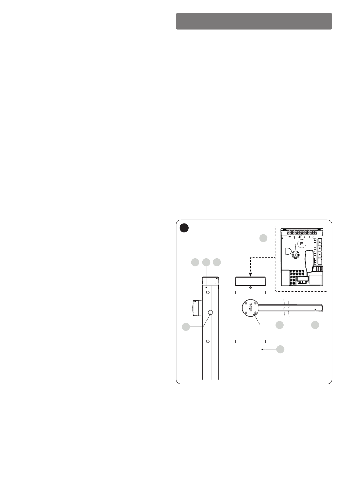
2.1 List of constituent parts . . . . . . . . . . . . . . . . . . . . . . . . . . . . 3
3 INSTALLATION. . . . . . . . . . . . . . . . . . . . . . . . . . . . . . . . . . . . . 4
3.1 Pre-installation checks. . . . . . . . . . . . . . . . . . . . . . . . . . . . . 4
3.2 Product usage limits . . . . . . . . . . . . . . . . . . . . . . . . . . . . . . 4
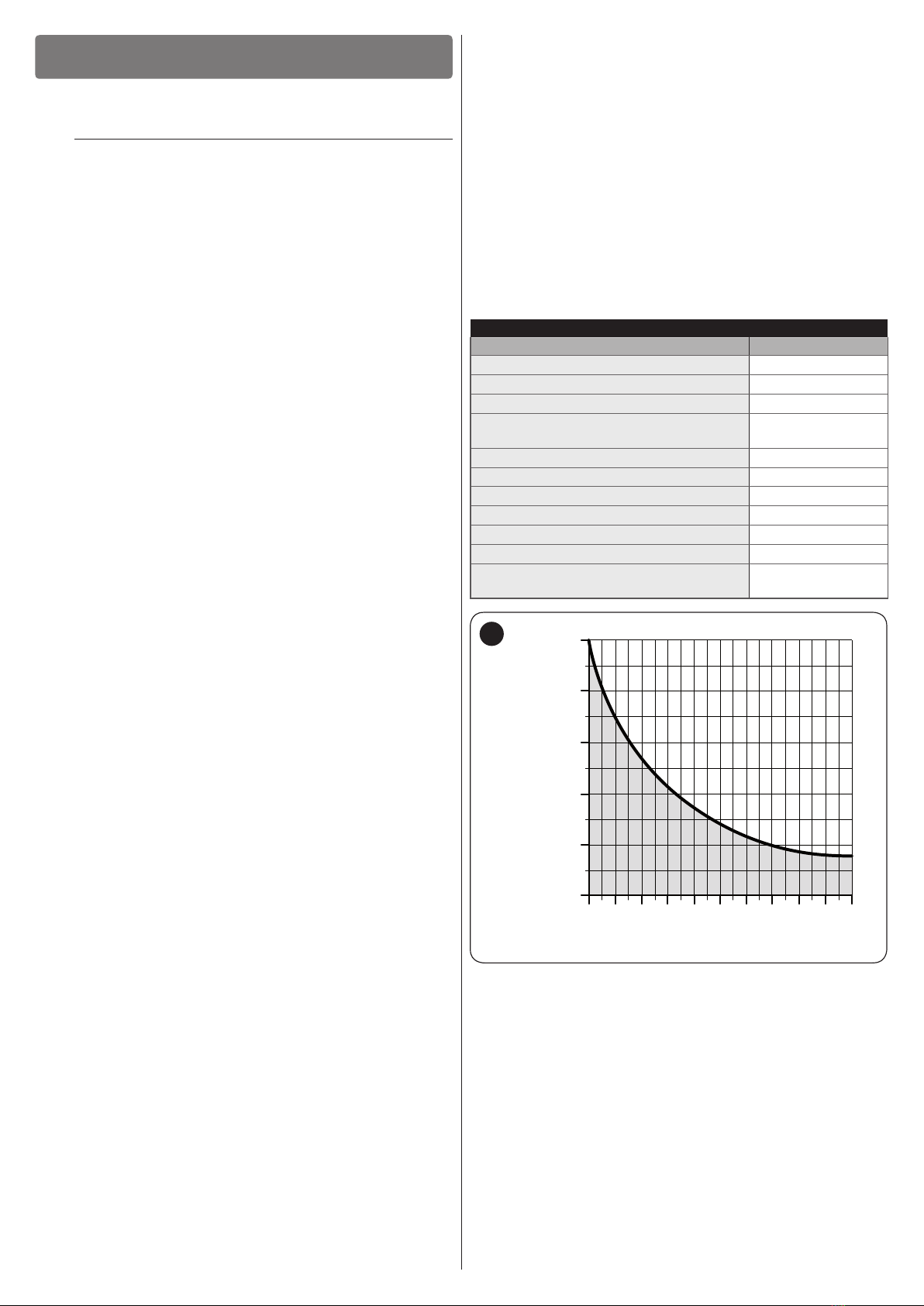
3.2.1 Product durability . . . . . . . . . . . . . . . . . . . . . . . . . . . . . . 4
3.3 Product identification and overall dimensions. . . . . . . . . . . 5
3.4 RECEIPT OF THE PRODUCT. . . . . . . . . . . . . . . . . . . . . . . . 5
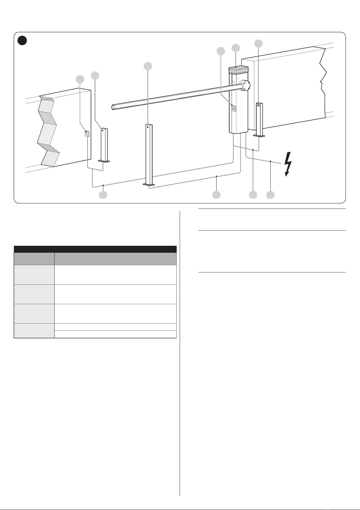
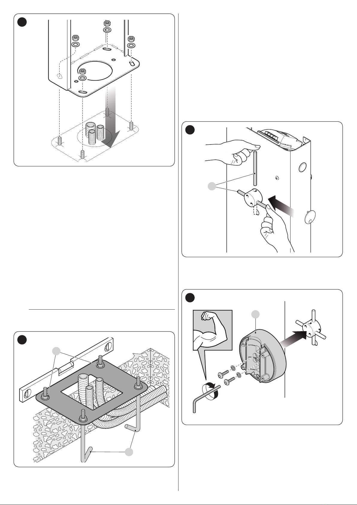
3.5 Pre-installation works. . . . . . . . . . . . . . . . . . . . . . . . . . . . . . 6
3.6 Adjusting the boom gate . . . . . . . . . . . . . . . . . . . . . . . . . . . 7
3.7 Installing the gearmotor. . . . . . . . . . . . . . . . . . . . . . . . . . . . 8
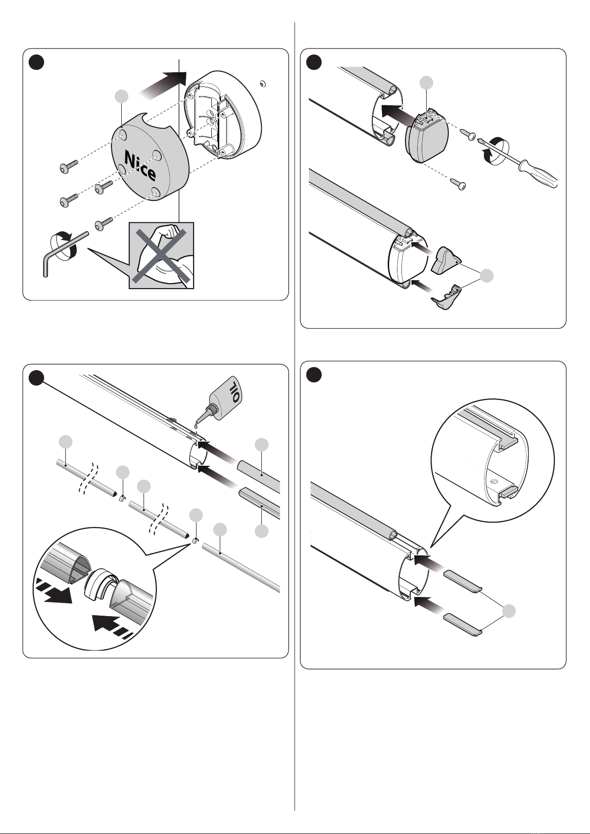
3.8 Installing the boom . . . . . . . . . . . . . . . . . . . . . . . . . . . . . . . 9
3.9 Adjusting the mechanical limit switches . . . . . . . . . . . . . . 11
3.10 Boom balancing. . . . . . . . . . . . . . . . . . . . . . . . . . . . . . . . . 11
3.11 Manually unlocking and locking the gearmotor. . . . . . . . . 12
4 ELECTRICAL CONNECTIONS . . . . . . . . . . . . . . . . . . . . . . . 12
4.1 Preliminary checks. . . . . . . . . . . . . . . . . . . . . . . . . . . . . . . 12
4.2 Wiring diagram and description of connections . . . . . . . . 13
4.2.1 Wiring diagram . . . . . . . . . . . . . . . . . . . . . . . . . . . . . . . 13
4.2.2 Description of connections . . . . . . . . . . . . . . . . . . . . . . 13
4.3 Addressing of devices connected with the BlueBUS
system . . . . . . . . . . . . . . . . . . . . . . . . . . . . . . . . . . . . . . . . 14
5 FINAL CHECKS AND START-UP. . . . . . . . . . . . . . . . . . . . . . 14
5.1 Power supply connection . . . . . . . . . . . . . . . . . . . . . . . . . 14
5.2 Device learning . . . . . . . . . . . . . . . . . . . . . . . . . . . . . . . . . 14
5.3 Learning of the mechanical stop positions . . . . . . . . . . . . 15
5.4 Checking the boom’s movement . . . . . . . . . . . . . . . . . . . . 15
5.5 Connecting other devices . . . . . . . . . . . . . . . . . . . . . . . . . 16
6 TESTING AND COMMISSIONING . . . . . . . . . . . . . . . . . . . . . 16
6.1 Testing . . . . . . . . . . . . . . . . . . . . . . . . . . . . . . . . . . . . . . . . 16
6.2 Commissioning . . . . . . . . . . . . . . . . . . . . . . . . . . . . . . . . . 17
7 PROGRAMMING . . . . . . . . . . . . . . . . . . . . . . . . . . . . . . . . . . 18
7.1 Using the programming buttons . . . . . . . . . . . . . . . . . . . . 18
7.2 Level 1 programming (ON-OFF) . . . . . . . . . . . . . . . . . . . . 19
7.2.1 Level 1 programming procedure . . . . . . . . . . . . . . . . . 19
7.3 Level 2 programming (adjustable parameters) . . . . . . . . . 20
7.3.1 Level 2 programming procedure . . . . . . . . . . . . . . . . . 20
7.4 Special functions . . . . . . . . . . . . . . . . . . . . . . . . . . . . . . . . 22
7.4.1 “Always open” function . . . . . . . . . . . . . . . . . . . . . . . . . 22
7.4.2 “Move anyway” function . . . . . . . . . . . . . . . . . . . . . . . . 22
7.4.3 “Maintenance notice” function . . . . . . . . . . . . . . . . . . . 22
7.5 Verifying the number of manoeuvres completed. . . . . . . . 22
7.6 Manoeuvre counter resetting. . . . . . . . . . . . . . . . . . . . . . . 23
8 TROUBLESHOOTING GUIDE . . . . . . . . . . . . . . . . . . . . . . . . 23
8.1 Troubleshooting. . . . . . . . . . . . . . . . . . . . . . . . . . . . . . . . . 23
7.7 Memory deletion . . . . . . . . . . . . . . . . . . . . . . . . . . . . . . . . 23
8.3 Signalling through warning light . . . . . . . . . . . . . . . . . . . . 24
8.2 Anomaly log. . . . . . . . . . . . . . . . . . . . . . . . . . . . . . . . . . . . 24
8.4 Signals on the control unit . . . . . . . . . . . . . . . . . . . . . . . . . 25
9 FURTHER DETAILS (Accessories). . . . . . . . . . . . . . . . . . . . 27
9.1 Modifying the STOP input configuration . . . . . . . . . . . . . . 27
9.2 Connecting an SM-type radio receiver . . . . . . . . . . . . . . . 27
9.3 EDSP digital selector and proximity reader for ETPB
transponder cards . . . . . . . . . . . . . . . . . . . . . . . . . . . . . . . 28
9.4 Connecting the boom lights (optional accessory). . . . . . . 28
9.5 Connecting the warning light or traffic light. . . . . . . . . . . . 29
9.6 Connecting and installing the back-up battery . . . . . . . . . 29
9.7 Connecting the Oview programmer . . . . . . . . . . . . . . . . . 30
9.8 Connecting the Solemyo solar energy system . . . . . . . . . 30
10 PRODUCT MAINTENANCE . . . . . . . . . . . . . . . . . . . . . . . . . . 31
11 PRODUCT DISPOSAL . . . . . . . . . . . . . . . . . . . . . . . . . . . . . . 31
12 TECHNICAL SPECIFICATIONS . . . . . . . . . . . . . . . . . . . . . . . 32
13 CONFORMITY . . . . . . . . . . . . . . . . . . . . . . . . . . . . . . . . . . . . 33
INSTRUCTIONS AND WARNINGS FOR THE USER . . . . . . 35
MAINTENANCE SCHEDULE (to be handed to the end
user). . . . . . . . . . . . . . . . . . . . . . . . . . . . . . . . . . . . . . . . . . . . 37

ENGLISH – 3
–The manufacturer declines all liability for damages to
property, objects or people resulting from failure to
observe the assembly instructions. In such cases, the
warranty for material defects shall not apply.
–The weighted sound pressure level of the emission A is
lower than 70 dB(A).
–Cleaning and maintenance reserved for the user must
not be carried out by unsupervised children.
–Before intervening on the system (maintenance, clean-
ing), always disconnect the product from the mains
power supply and from any batteries.
–Inspect the system frequently, in particular the cables,
springs and supports to detect any imbalances and
signs of wear or damage. Do not use the product if it
needs to be repaired or adjusted, because defective
installation or incorrect balancing of the automation can
lead to injuries.
–The packing materials of the product must be disposed
of in compliance with local regulations.
–Keep persons away from the gate when it is manoeu-
vred using the control elements.
–When operating the gate, keep an eye on the automat-
ed mechanism and keep all bystanders at a safe dis-
tance until the movement has been completed.
–Do not operate the product if anyone is working near-
by; disconnect its power supply before permitting such
work to be done.
1.2 INSTALLATION WARNINGS
–Prior to installing the drive motor, check that all me-
chanical components are in good working order and
properly balanced, and that the automation can be ma-
noeuvred correctly.
–If the gate being automated has a pedestrian gate, the
system must be equipped with a control device that in-
hibits the motor’s operation when the pedestrian gate
is open.
–Make sure that the control elements are kept far from
moving parts but nonetheless directly within sight. Un-
less a selector is used, the control elements must be
installed at least 1.5 m above the ground and must not
be accessible.
–If the opening movement is controlled by a re-sensing
system, make sure that any windows larger than 200
mm are closed using the control elements.
–Prevent and avoid any form of entrapment between the
moving and xed parts during the manoeuvres.
–Permanently afx the label concerning the manual ma-
noeuvre near its actuating element.
–After installing the drive motor, make sure that the
mechanism, protective system and all manual manoeu-
vres function properly.
PRODUCT DESCRIPTION AND
INTENDED USE
2
2 PRODUCTDESCRIPTIONANDINTENDEDUSE
S-BAR are electromechanical boom gates for residential and
industrial use, which control the opening and closing of a drive-
way.
These barriers are equipped with an electromechanical gear-
motor with a 24 V motor, an electric limit switch system and a
warning light incorporated in the cover (optional accessory)..
The control unit is congured for being connected to the var-
ious devices belonging to the Nice Opera System and to the
“Solemyo” solar power system (see paragraph “Connecting
the Solemyo solar energy system“).
The barriers work on electricity and in case of a power outage
(blackout), the boom can be unlocked manually and moved
by hand. Alternatively, it is possible to use the back-up battery
(model PS124 - optional accessory) which ensures that certain
manoeuvres can be carried out in the rst few hours of a power
outage. To prolong this period or increase the number of al-
lowed manoeuvres, it is necessary to activate the “Stand-by”
function (see “Table 5“).
Important notes for using the manual:
–throughout this manual, the term “boom gate” refers to the
product “S-BAR”
–the accessories mentioned in the manual are optional.
a
Any use of the product other than the intended use
described is not allowed!
2.1 LIST OF CONSTITUENT PARTS
“Figure 1” shows the main parts making up the S-BAR.
C
EA
B
BA
F
D
L1L2L3L4L5L6L7L8
Flash
Bluebus
Stop
Sbs
Open
Close
Flash
Bluebus
Stop Sbs Open Close
Aerial
IBT4N
1
ABoom support
B Gearmotor containment box
CCover
DElectronic control and command unit
EBoom
FLocking/unlocking key

4 – ENGLISH
INSTALLATION
3
3 INSTALLATION
3.1 PRE-INSTALLATION CHECKS
a
The installation must be carried out by qualied
personnel in compliance with the current legisla-
tion, standards and regulations, and with the in-
structions provided in this manual.
Before proceeding with the product’s installation, it is necessary
to:
–check the integrity of the supply
–check that all the materials are in good working order and
suited to the intended use
–check whether it is possible to observe the operating limits
specied in the paragraph “Product usage limits“
–check that the installation location is compatible with the over-
all clearance of the product (see “Figure 3“)
–check that the surface chosen for installing the boom gate is
solid and can ensure stable anchorage
–make sure that the installation area is not subject to ooding; if
necessary, the product must be installed appropriately raised
above ground level
–check that the space surrounding the boom gate allows for
executing the manual manoeuvres easily and safely
–check that there are no obstacles along the boom’s path ca-
pable of hampering the opening and closing manoeuvres
–check that each device to be installed lies in a position that is
protected against the risk of accidental impact.
–verify that the mounting positions of the various devices are
protected against impacts and that the mounting surfaces are
sufciently sturdy
–prevent any parts of the automation from being immersed in
water or other liquids
–keep the product away from heat sources and open ames
and acid, saline or potentially explosive atmospheres; these
may damage the product and cause malfunctions or danger-
ous situations
–connect the control unit to an electricity supply line equipped
with a safety earthing system
3.2 PRODUCT USAGE LIMITS
Before proceeding with the product’s installation, it is necessary
to:
–check that all the values appearing in the “TECHNICAL SPEC-
IFICATIONS” chapter are compatible with the intended use
–check that the estimated durability (refer to the paragraph “
Product durability”) is compatible with the intended use
–check that all limitations, conditions and warnings appearing
in this manual can be fully observed.
3.2.1 Product durability
The product’s durability is its average economic life value and is
strongly inuenced by the degree of severity of the manoeuvres:
in other words, the sum of all factors that contribute to product
wear.
To estimate the durability of your automated device, proceed
as follows:
1. add the values of the items in “Table 1” relative to the
system’s conditions
2. in the graph shown in “Figure 2”, from the value obtained
above, trace a vertical line until it intersects the curve;
from this point trace a horizontal line until it intersects the
line of the “manoeuvre cycles”. The value obtained is the
estimated lifetime of your product.
The durability values shown in the graph can only be obtained if
the maintenance schedule is strictly observed – see the “PROD-
UCT MAINTENANCE” chapter. The durability is estimated on
the basis of the design calculations and the results of tests ef-
fected on prototypes. Being an estimate, therefore, it offers no
explicit guarantee of the product’s actual useful life.
Example of durability calculation: S4-BAR
“Table 1” shows the “severity indices” for this type of installation:
15% (“Boom with lights model XBA4”), 10% (“Presence of salt”).
These indicators must be added together to obtain the overall
severity index, which in this case is 25%. With the value calcu-
lated (25%), identify along the graph’s horizontal axis (“severity
index”) the value corresponding to the number of “manoeuvre
cycles” that the product can perform throughout its lifetime =
roughly 240.000 cycles.
Table 1
PRODUCT DURABILITY
Severity index
Boom with lights model XBA4 15
Speed levels 3 and 4 5
Speed level 5 20
Manoeuvre interrupted by photocell >
10% 15
Manoeuvre interrupted by Stop > 10% 25
Braking 10
Force equal to 5 or 6 10
Force equal to 7 or 8 10
Presence of salinity 10
Presence of dust and sand 10
Ambient temperature above 40°C and
below 0°C 15
100 20 30 40 50 60 70 80 90
100
Manoeuvre cycles (n°)
Severity index (%)
100.000
0
200.000
300.000
400.000
500.000
2

ENGLISH – 5
3.3 PRODUCT IDENTIFICATION AND OVERALL
DIMENSIONS
The overall dimensions and the label (A), which allows for iden-
tifying the product, are shown in “Figure 3”.
295 mm
179,5 mm
1146 mm
826 mm
330 mm
A
3
3.4 RECEIPT OF THE PRODUCT
All the components contained in the product’s packaging are
illustrated and listed below.
AB
C
F
GH
E
D
4
ABoom gate with integrated control unit
BBoom cover and support
C 2 photocell boxes
D2 boom supporting brackets
E Fixed boom cap; 2 connectors for rubber impact protec-
tors; 2 connectors without rubber impact protectors
FKeys for manually locking and unlocking the boom; key
for the cover lock; metal smallware (screws, washers,
etc.)
GFoundation plate
H4 anchor bolts

6 – ENGLISH
3.5 PRE-INSTALLATION WORKS
The gure shows an example of an automation system, constructed using Nice components.
AB
C
2 3 2 1
ADB
5
A Photocells
B Photocells on column
C Key selector
D Boom gate cubicle
Table 2
TECHNICAL SPECIFICATIONS OF ELECTRICAL CABLES
Identication
no. Cable characteristics
1
GEARMOTOR POWER SUPPLY cable
1 cable 3 x 1.5 mm2
Maximum length 30 m [note 1]
2
BLUEBUS cable
1 cable 2 x 0.5 mm2
Maximum length 30 m
3
KEY SELECTOR cable
1 cable 4 x 0.25 mm2(note 2)
Maximum length 30 m
Other cables OPTIONAL WARNING LIGHT cable supplied
BOOM LIGHTS cable
These above-mentioned components are positioned according
to a typical standard layout. Using the layout in “Figure 5” as a
reference, dene the approximate position in which each com-
ponent of the system will be installed.
Note 1 If the power supply cable is longer than 30 m, a cable
with larger cross-sectional area (3 x 2.5 mm2) must be
used and a safety earthing system must be installed
near the automation.
Note 2 If, instead of the selector, an ETPB transponder card
reader or EDSP digital keypad is used, a twin-lead ca-
ble will be sufcient (2 x 0.5 mm2).
a
The cables used must be suited to the type of envi-
ronment of the installation site.
a
When laying the pipes for routing the electrical ca-
bles, take into account that any water deposits in
the junction boxes may cause the connection pipes
to form condensate inside the control unit, thus
damaging the electronic circuits.
a
Before proceeding with the installation, prepare the
required electrical cables by referring to “Figure 5”
and to that stated in the “TECHNICAL SPECIFICA-
TIONS” chapter.

ENGLISH – 7
3.6 ADJUSTING THE BOOM GATE
The boom gate leaves the factory with the boom closing ma-
noeuvre set towards the left.
To set the closing manoeuvre towards the right, proceed as fol-
lows:
1. remove the upper cover (A) of the boom gate cubicle
A
6
2. loosen the two screws fastening the cubicle panel
7
3. remove the balancing spring, by detaching it from the bal-
ancing lever
8
4. loosen the bolt fastening the balancing spring
5. unlock the gearmotor (refer to the “Manually unlocking
and locking the gearmotor” paragraph) and turn the bal-
ancing lever by 90°
90°
9

8 – ENGLISH
6. vigorously tighten the bolt fastening the balancing spring
10
7. attach the balancing spring in the correct position
11
8. if the gearmotor was previously unlocked, lock it again.
3.7 INSTALLING THE GEARMOTOR
a
Incorrect installation may cause serious physical
injury to the person working on the system or to its
future users.
Before starting to assemble the automation, com-
plete the preliminary checks described in the “Pre-
installation checks” and “Product usage limits”
paragraphs.
If there is a support surface:
1. open the cubicle panel
12
2. place the cubicle on the anchoring surface and mark the
points corresponding to the slots
13
3. move the cubicle and drill the surface through the marked
points
4. insert 4 expansion bolts (not supplied)
5. arrange the cubicle properly and secure it with the appro-
priate nuts and washers (not supplied).

ENGLISH – 9
14
If there is no support surface:
1. dig the hole to insert the foundation plate
Note The anchoring surface must be completely at and
smooth. If the surface is made of concrete, the latter
must be at least 0,15 m thick and must be suitably rein-
forced with iron cages. The concrete must have a vol-
ume above 0.2 m3(a 0.25 m thickness corresponds to
0.8 m2, that is, equal to a square base with sides each
measuring roughly 0.9 m). The plate can be anchored to
the concrete using the 4 expansion bolts, equipped with
12 MA screws capable of withstanding a tensile load of
at least 400 kg. If the anchoring surface is made of a
different material, it is necessary to verify its consistency
and whether the four anchoring points can withstand a
load of at least 1,000 kg. Use the 12 MA screws to fas-
ten the plate.
2. arrange the pipes for routing the electrical cables
3. fasten the four anchor bolts (A) to the foundation plate, in-
serting a nut and washer (supplied) on each, on the upper
and lower sides of the plate
m
The lower nut must be screwed up to the end of the
thread.
A
B
15
4. pour the concrete and, before it starts to set, place the
foundation plate ush with the surface, parallel to the
boom and perfectly level
5. wait for the concrete to set completely, which generally
takes two weeks
6. remove the four upper nuts and washers (B) from the an-
chor bolts
7. open the cubicle panel (“Figure 7“)
8. arrange the cubicle properly and secure it with the ap-
propriate nuts and washers removed previously (“Figure
14“).
3.8 INSTALLING THE BOOM
Proceed as follows to mount the boom of the gate:
1. insert the two pins (A) through the appropriate housings
on the exit motor shaft
A
16
2. place the support (B) on the exit motor shaft, orienting it in
the “vertical boom” position
3. fasten it with the appropriate screws and open Grower
washers; tighten vigorously
B
17

10 – ENGLISH
4. position the cover (C) of the support and fasten it with the
6 screws provided; leave the screws loose
C
18
5. lightly oil the aluminium rail on both sides
6. along the entire length of the boom, insert the rubber im-
pact protectors through the slots (D) alternating them with
the relevant joints (E); the rubber protector can protrude
roughly 1 cm from the end of the boom
D
D
D
E
E
D
D
19
7. put on the boom cap (F) and secure it with the two screws
8. position and t together the two rubber protector caps (G)
F
G
20
9. insert, through the opposite end with respect to the cap,
the boom supporting plates (H)
H
21

ENGLISH – 11
10. insert the complete boom into the shell (I) of the support
all the way to the end
11. vigorously tighten the 4 screws of the support inserted
previously.
I
22
l
After installing the boom and the rubber impact pro-
tector, before proceeding further, the other acces-
sories – if relevant – must be installed on the boom.
To install them, refer to the respective instruction
manuals.
3.9 ADJUSTING THE MECHANICAL LIMIT
SWITCHES
To adjust the limit switches, proceed as follows:
1. unlock the gearmotor with the relevant key provided (refer
to the “Manually unlocking and locking the gearmotor”
paragraph)
2. manually move the boom so that it completes a full open-
ing and closing manoeuvre
3. turn the screws of the mechanical stops (A - B) to adjust
the boom’s horizontal position, when it is closed, and its
vertical position, when it is open
B
A
23
4. after making the adjustments, tighten the nuts vigorously.
3.10 BOOM BALANCING
The boom balancing operation is used to nd the best balance
between the overall weight of the boom, inclusive of the installed
accessories, and the force opposed by the tension of the bal-
ancing spring.
To verify the spring tension, proceed as explained below.
1. unlock the gearmotor with the relevant key provided (refer
to the “Manually unlocking and locking the gearmotor”
paragraph)
2. manually move the boom to about half-way (45°) and
leave it stationary
3. if the boom tends to rise, reduce the tension of the spring
(A). On the other hand, if the boom tends to fall, increase
the spring tension
4. put the boom in the maximum opening position
5. detach the balancing spring from its housing (B) and
shift its anchoring point towards the centre, to reduce
the spring tension, or towards the outside to increase the
spring tension
45°
45°
A
B
24
Note The imbalance is acceptable when the force required
to move the boom during the opening and closing ma-
noeuvres and in all other positions is less than or equal
to half the maximum torque value (for this product,
roughly 5 kg at 1 m).
6. repeat the operation by positioning the boom also at
roughly 20° and 70°. If the boom remains stationary in its
position, it means that it is correctly balanced; a slight im-
balance is allowed, but the boom must never move sub-
stantially
7. lock the gearmotor.

12 – ENGLISH
3.11 MANUALLY UNLOCKING AND LOCKING THE
GEARMOTOR
The gearmotor is equipped with a mechanical unlocking system
that allows for opening and closing the boom manually.
These manual operations should only be performed in case of
a power outage, malfunctions or during the installation phases.
To unlock the device:
1. turn the key slot cover
2. insert the key (A) and turn it by 180° towards the left or
right
180°
A
180°
A
25
3. the gate leaf can now be moved manually to the desired
position.
To lock the device:
1. turn the key (A) back to its initial position
2. remove the key
3. turn the key slot cover.
ELECTRICAL CONNECTIONS
4
4 ELECTRICALCONNECTIONS
4.1 PRELIMINARY CHECKS
f
All electrical connections must be made with the
system disconnected from the mains electricity and
with the back-up battery (if present) disconnected.
a
The connection operations must only be carried out
by qualied personnel.
To make the electrical connections:
1. remove the upper cover (A) of the boom gate cubicle
A
26
2. feed the electrical cables inside the cubicle towards the
left, starting from the base and moving towards the control
unit
3. feed the power supply cable through the cable clamp and
connect it to the 3-contact terminal with fuse
4. tighten the screw of the cable clamp
LN
27
5. connect the remaining cables, by consulting the wiring
diagram in “Figure 28”. For greater convenience, the ter-
minals are removable.

ENGLISH – 13
4.2 WIRING DIAGRAM AND DESCRIPTION OF CONNECTIONS
4.2.1 Wiring diagram
NO
NC
8K2 NO
NO
NO NO
TX
Bluebus
Bluebus
RX
Bluebus
MOTB/MOFB
L1L2L3L4L5L6L7L8
Flash
Bluebus
Stop
Sbs
Open
Close
Flash
Bluebus
Stop Sbs Open Close
Aerial
IBT4N
28
4.2.2 Description of connections
Table 3
ELECTRICAL CONNECTIONS
Terminals Description
FLASH
Output for warning light; it is possible to connect 12 V max 21 W lamps or a Nice LUCY B, MLB or MLBT
warning light.
It can also be programmed for other functions (refer to the “PROGRAMMING” chapter) or recongured
through the Oview programmer.
BLUEBUS
This terminal can be used to connect compatible devices, which are all connected in parallel with only two
wires carrying both the electric power and communication signals.
For further information on the BlueBUS, refer to the “Addressing of devices connected with the BlueBUS
system” paragraph.
STOP
Input for devices that suspend or even stop the current manoeuvre; “Normally Closed” and “Normally Open”
contacts or xed resistor devices can be connected by suitably conguring the input.
For further information on the STOP function, refer to the “Modifying the STOP input conguration”
paragraph.
SbS Input for devices that control the movement in Step-by-Step mode; it is possible to connect “Normally Open”
contacts.
OPEN Input for devices that control the opening movement only; it is possible to connect “Normally Open” contacts.
CLOSE Input for devices that control the closing movement only; it is possible to connect “Normally Open” contacts.
ANTENNA input for connecting the radio receiver antenna; the antenna is incorporated in Nice LUCY B, MLB and MLBT
warning lights.
a
If the programming of the outputs is modied, check that the connected device matches the type of voltage
chosen.

14 – ENGLISH
4.3 ADDRESSING OF DEVICES CONNECTED
WITH THE BLUEBUS SYSTEM
By means of addressing using special jumpers, the “BlueBUS”
system enables the user to make the control unit recognise the
photocells and assign the correct detection function.
The addressing operation must be done on both the TX and RX
photocells (setting the jumpers in the same way), while making
sure there are no other pairs of photocells with the same ad-
dress.
A photocell addressing diagram is shown below, based on the
type of photocell.
FOTO 2
FOTO II
FOTO 2 II
FOTO 1
FOTO II
FOTO
29
Table 4
PHOTOCELL ADDRESSES
Photocell Position of the
jumpers
FOTO (PHOTO)
External photocell h = 50 activated during
the closing phase (stops and reverses the
gate’s movement)
FOTO II (PHOTO II)
External photocell h = 100 activated
during the closing phase (stops and
reverses the gate’s movement)
FOTO 1 (PHOTO 1)
Internal photocell h = 50 activated during
the closing phase (stops and reverses the
gate’s movement)
FOTO 1 II (PHOTO 1 II)
Internal photocell h = 100 activated during
the closing phase (stops and reverses the
gate’s movement)
FOTO 2 (PHOTO 2)
External photocell activated during the
opening phase
FOTO 2 II (PHOTO 2 II)
Internal photocell activated during the
opening phase
FOTO 3 (PHOTO 3)
Single photocell covering the entire
automation
m
At the end of the installation procedure, or after
photocells or other devices have been removed,
it is necessary to complete the learning procedure
(see the “Device learning” paragraph).
FINAL CHECKS AND START-UP
5
5 FINALCHECKSANDSTART-UP
5.1 POWER SUPPLY CONNECTION
a
The power supply connections must only be made
by qualied and experienced personnel possessing
the necessary requirements and in full conformity
to the laws, regulations and standards in force.
Connect the control unit to a power line equipped with a safety
earthing system. Install a circuit breaker with a contact gap that
ensures full disconnection in the Category III overvoltage condi-
tions, or mount a plug and socket system.
As soon as the product is powered, a few simple checks should
be carried out:
1. check that the display switches on.
2. make sure that the LEDs on the photocells (both the TX
and RX) also ash; the type of ashing is irrelevant, since
it depends on other factors.
3. check that the device connected to the FLASH output or
the LED warning light XBA7 is switched off (with factory
setting).
If the above conditions are not satised, immediately switch
off the power supply to the control unit and carefully check the
electrical connections.
Further useful information on searching and diagnosing faults is
included in the “Troubleshooting” paragraph.
5.2 DEVICE LEARNING
Once the power supply has been connected, the control unit
must recognise the devices connected to the “BlueBUS” and
“STOP” inputs. Prior to this phase, LEDs “L1” and “L2” will ash
to signal that the device learning procedure must be performed.
m
The learning phase must be carried out even if no
device is connected to the control unit.

ENGLISH – 15
L1L2L3L4L5L6
L7
Flash
Bluebus
Stop
Sbs
Open
Close
Flash
Bluebus
Stop Sbs Open Close
L1
L2
30
To do this:
1. simultaneously press and hold the pand obuttons
2. release the buttons when LEDs “L1” and “L2” start ash-
ing quickly (after roughly 3 seconds)
3. wait a few seconds until the control unit has completed the
device learning phase
4. once this phase terminates, the “Stop” LED must be lit
and LEDs “L1” and “L2” must switch off (LEDs “L3” and
“L4” could start ashing).
The self-learning phase of the connected devices can be re-
peated at any time also after the installation, for example when-
ever a device must be added.
5.3 LEARNING OF THE MECHANICAL STOP
POSITIONS
Once the connected devices have been learned, the mechani-
cal stop positions must be learned (maximum opening and max-
imum closing).
L1L2L3L4L5L6L7L8
Flash
Bluebus
Stop
Sbs
Open
Close
31
To do this:
1. unlock the gearmotor with the relevant key provided (refer
to the “Manually unlocking and locking the gearmotor”
paragraph)
2. manually move the boom to about half-way (45°) and
leave it stationary
3. lock the gearmotor
4. simultaneously press and hold the qand obuttons
5. release the buttons when the manoeuvre starts (after
roughly 3 seconds)
6. wait for the control unit to complete the learning phase:
boom closing, opening and closing
7. press the pbutton to perform a complete boom opening
manoeuvre
8. press the qbutton to perform a complete boom closing
manoeuvre
9. while the manoeuvres are being executed, make sure that
the boom’s balancing lever strikes the mechanical stops
of the limit switch. If this does not occur, stop the proce-
dure, adjust the mechanical stops of the limit switch and
repeat the procedure from the beginning.
During the execution of these procedures, the control unit mem-
orises the force required to perform these manoeuvres.
a
Do not interrupt the execution of the manoeuvres: if
this occurs, the entire procedure must be repeated
from the beginning.
a
If case of changes to the speed, motor direction and
long/short slowdown, the entire procedure must be
repeated again.
5.4 CHECKING THE BOOM’S MOVEMENT
Once the devices have been learned, it is advisable to carry out
a few manoeuvres in order to verify that the gate moves prop-
erly.
L1L2L3L4L5L6L7L8
Flash
Bluebus
Stop
Sbs
Open
Close
32
To do this:
1. press the p button to command an “Open” manoeuvre;
check that the boom starts slowing down before reaching
the open position
2. press the q button to command a “Close” manoeuvre;
check that the boom starts slowing down before reaching
the closed position
3. during the manoeuvre, check that the LED warning light, if
present, ashes alternatively on and off every 0.5 seconds
4. open and close the gate several times to make sure that
there are no points of excessive friction and that there are
no defects in the assembly or adjustments.
After the initial opening and closing manoeuvres, the values of
parameters “L5” and “L6” of the Level 2 programming menu will
be automatically modied by the control unit to optimally adapt
to the installation.

16 – ENGLISH
5.5 CONNECTING OTHER DEVICES
If the user needs to power external devices, such as a radio
receiver or the light of the key selector switch, power can be
tapped as shown in the gure.
The power supply voltage is 24Vc -30% ÷ +50% with a maxi-
mum available current of 100mA.
STOP SBS
(+)(-)
33
TESTING AND COMMISSIONING
6
6 TESTINGANDCOMMISSIONING
These are the most important phases of the automation’s con-
struction, as they ensure maximum safety of the system. The
test can also be used to periodically verify the devices making
up the automation.
m
Testing and commissioning of the automation must
be performed by skilled and qualied personnel,
who are responsible for the tests required to ver-
ify the solutions adopted according to the risks
present, and for ensuring that all legal provisions,
standards and regulations are met, in particular all
the requirements of the EN 12445 standard, which
denes the test methods for checking gate automa-
tions.
The additional devices must undergo specic testing, both in
terms of their functions and their proper interaction with the con-
trol unit. Refer to the instruction manuals of the individual devic-
es.
6.1 TESTING
To run the test:
1. verify that all the instructions stated in the “GENERAL
SAFETY WARNINGS AND PRECAUTIONS” chapter
have been strictly observed
2. check that the boom is correctly balanced (see paragraph
“Boom balancing“)
3. check that the manual unlocking device works properly
(see paragraph “Manually unlocking and locking the
gearmotor“)
4. using the control devices (transmitter, control push-but-
ton, key selector, etc.), test the boom opening, closing
and stopping phases, ensuring that the movement match-
es the specications. Several tests should be conducted
to assess the boom’s movement and to check for any as-
sembly or adjustment defects or any particular points of
friction
5. check, one-by-one, that all safety devices mounted on the
system (photocells, sensitive edges, etc.) work properly.
Each time a device intervenes, the “Bluebus” LED on the
control unit will emit two faster ashes to conrm the rec-
ognition
6. verify the correct operation of the photocells in the follow-
ing way:
–depending on whether one or two pairs of photocells
have been installed, one or two blocks of rigid ma-
terial (e.g. wooden panels) are required, measuring
70x30x20 cm. Each block must have three sides of re-
ective material (e.g. mirror or glossy white paint), one
for each dimension, and three sides of opaque material
(e.g. matt black paint). To test the photocells positioned
50 cm above the ground, the block must be placed on
the ground, or raised to 50 cm when testing photocells
positioned 1 m above the ground
–if the test is on a pair of photocells, the testing block
must be placed directly under the centre of the boom
with the 20 cm sides facing the photocells and moved
along the entire length of the boom
300
200
700
500
34
–if the test is on two pairs of photocells, the test must
rst be performed individually for each pair of photo-
cells using one testing block and then repeated using
two testing blocks; each testing block must be posi-
tioned laterally in relation to the centre of the boom, at
a distance of 15 cm and then moved along the entire
length of the boom
300
200
700
300
200
700
500
150
150
35

ENGLISH – 17
–during these tests, the testing block must be detected
by the photocells in any position it lies along the entire
length of the boom
7. check that there are no interferences between the photo-
cells and other devices:
–block the line of sight between the pair of photocells
with a cylinder (diameter 5 cm, length 30 cm), by mov-
ing it close to the TX photocell rst then next to the RX
photocell and then at the mid-point between the two
36
–check that the device intervenes in all cases, switching
from the active to the alarm status and vice-versa
–check that it triggers the intended action in the control
unit (e.g. a reversal of the movement during the closing
manoeuvre)
8. check on the safeguard against the lifting hazard: in
automations with vertical movement it is necessary to ver-
ify that there is no lifting hazard. This test can be carried
out in the following way:
–hang a 20 kg load (e.g. a sand bag) midway along the
boom’s length
–send an opening command and check that during the
manoeuvre the boom does not exceed a height of 50
cm above its closed position
–if the boom exceeds this height, the motor force must
be reduced (refer to the chapter “PROGRAMMING“)
9. if potentially dangerous situations due to the boom’s
movement have been prevented by limiting the impact
force, the latter must be measured according to the EN
12445 standard and, if the “motor force” control is used
to aid the system in reducing the impact force, it is neces-
sary to test various adjustments to nd the one that gives
the best results
10. checking the efciency of the unlocking system:
–put the boom in the closed position and manually un-
lock it (see paragraph “Manually unlocking and lock-
ing the gearmotor“)
–verify that this occurs smoothly
–verify that the manual force to move the boom during
the opening phase does not exceed 200 N (roughly 20
kg)
–the force is measured perpendicularly to the boom at 1
m from the rotation axis
11. verication of the power supply disconnection sys-
tem: operate the power disconnection device and dis-
connect any available back-up batteries; check that all
the LEDs on the control unit are OFF and that the boom
remains stationary when a command is sent. Check the
efciency of the locking system to prevent any uninten-
tional or unauthorised connection.
6.2 COMMISSIONING
a
Commissioning can only be performed after all test-
ing phases have been successfully completed.
a
Before commissioning the automation, ensure that
the owner is properly informed of all residual risks
and hazards.
a
The gate cannot be commissioned partially or un-
der “temporary” conditions.
To commission the automation:
1. compile the automation’s technical le, which must in-
clude the following documents: overall drawing of the
automation, wiring diagram, risk assessment and relative
solutions adopted, the manufacturer’s declaration of con-
formity for all devices used and the declaration of con-
formity compiled by the installer
2. afx a permanent label or sign on the cubicle specifying
the operations for unlocking the gate and manoeuvring it
manually “Figure 37“
37
3. afx a data plate to the cubicle specifying at least the
following data: type of automation, name and address of
the manufacturer (responsible for commissioning), serial
number, year of manufacture and CE mark
4. compile the declaration of conformity of the automation
and hand it to the owner of the automation
5. compile the User Manual of the automation and hand it to
the owner of the automation
6. compile and provide the owner with the automation’s
“Maintenance schedule”, containing the maintenance in-
structions for all the automation’s devices.
l
For all the above-mentioned documentation, Nice –
through its technical assistance service – provides
the following: pre-completed forms.

18 – ENGLISH
PROGRAMMING
7
7 PROGRAMMING
There are 3 buttons on the control unit: p, oand q(“Figure
38”) which can be used both to command the control unit during
the testing phase and to programme the available functions.
L1L2L3L4L5L6L7L8
Flash
Bluebus
Stop
Sbs
Open
Close
L1 ... L8
38
The available programmable functions are grouped into two
levels and their operating status is signalled by eight LEDs “L1
... L8” located on the control unit (LED lit = function enabled;
LED off = function disabled).
7.1 USING THE PROGRAMMING BUTTONS
pButton for commanding the boom gate opening
Selection button during the programming phase.
oButton used to stop a manoeuvre
If pressed for more than 5 seconds, it allows for entering
the programming mode.
qButton for commanding the boom gate closing
Selection button during the programming phase.

ENGLISH – 19
7.2 LEVEL 1 PROGRAMMING (ON-OFF)
All the Level 1 functions are factory-set to “OFF” with the exception of parameter “L5” and can be modied at any time. To check
the various functions, refer to “Table 5”. Take care during modication procedures, as there is a maximum time interval of 10 sec-
onds between pressing of different buttons; otherwise the procedure terminates automatically and stores the changes made up to
that time.
7.2.1 Level 1 programming procedure
m
The user has maximum 10 seconds to press the buttons consecutively during the programming procedure,
after which time the procedure terminates automatically and memorises the changes made up to then.
To perform Level 1 programming:
1. press and hold the obutton until LED “L1” starts ashing
2. release the obutton when LED “L1” starts ashing
3. press the por q button to move the ashing LED to the LED associated with the function to be modied
4. press the obutton to change the status of the function:
–short ash = OFF
–long ash = ON
5. wait 10 seconds (maximum time) to exit the programming mode.
l
To set other functions to “ON” or “OFF”, while the procedure is running, repeat points 2 and 3 during the phase
itself.
Table 5
LEVEL 1 FUNCTIONS (ON-OFF)
LED Function Description
L1 Automatic closing
Function ENABLED: after an opening manoeuvre there is a pause (equal to the set pause time), after
which the control unit automatically starts a closing manoeuvre. The pause time is set by default to 30
seconds.
Function NOT ENABLED: the system works in “semi-automatic” mode.
L2 Close after photo
Function ENABLED: the behaviour changes depending on whether the “Automatic Closing” function is
enabled or not.
When “Automatic Closing” is disabled: the boom gate always reaches the fully open position (even if the
Photo disengages rst). When Photo disengages, automatic closing is triggered with a 5-second pause.
When “Automatic Closing” is enabled: the opening manoeuvre stops immediately after the photocells have
disengaged. After 5 seconds, the gate will start closing automatically.
The “Close After Photo” function is always disabled in manoeuvres interrupted by a Stop command.
Function DISABLED: the pause time is that which has been programmed or automatic re-closing will not
take place if the function is disabled.
L3 Always Close
Function ENABLED: in the event of a blackout, even of short duration, if the control unit detects that the
gate is open once the electricity is restored, it automatically starts a closing manoeuvre, preceded by a
3-second pre-ashing sequence.
Function DISABLED: when the electricity is restored, the gate remains in the same position.
L4 Stand-by
Function ENABLED: 1 minute after the completion of the manoeuvre, the control unit switches off the
BlueBUS output (and, therefore, the devices) and all LEDs, with the exception of the BlueBUS LED, which
ashes more slowly. When the control unit receives a command, it restores full operation.
Function DISABLED: there will be no reduction in consumption.
This function is useful, in particular, during operation with the back-up battery.
L5 Long slowdown
Function ENABLED: allows for doubling the space from which the slowdown starts, during both the
opening and closing manoeuvres.
Function DISABLED: short slowdown.
L6 Pre-ashing
Function ENABLED: a 3-second pause can be added between the switching on of the warning light and
the start of the manoeuvre, to warn the user in advance of a potentially dangerous situation.
Function DISABLED: the signalling of the warning light coincides with the start of the manoeuvre.
L7 Sensitivity
Function ENABLED: allows for considerably increasing the motor’s sensitivity in detecting obstacles. If
used to aid impact force detection, the “Speed” and “Motor force” parameters in the Level 2 menu must
also be adjusted.
L8 Motor rotation
direction
Function ENABLED: allows for inverting the motor’s rotation direction in order to install the barrier to the
right.
Function DISABLED: the factory setting, with the barrier closing towards the left.
WARNING: when this function is enabled, the “Opening” and “Closing” positions must be learned (see the
“Learning of the mechanical stop positions” paragraph).
l
During normal operation, LEDs “L1 ... L8” are on/off depending on the status of the respective function; for
example, “L1” is lit when the “Automatic Closing” function is enabled.
l
During the manoeuvre, LEDs “L1 ... L8” ash to signal the force required to move the boom at that time. If “L1”
ashes, the force required is low and so forth, until LED “L8” ashes to signal the maximum force.

20 – ENGLISH
l
Please note that there is no relation between the force level indicated by the LEDs during the movement (which
is an absolute value) and the level indicated by the LEDs during the force (which is a relative value) program-
ming phase. See LEDs “L5” and “L6” in “Table 6”.
7.3 LEVEL 2 PROGRAMMING (ADJUSTABLE PARAMETERS)
All the Level 2 parameters are factory-set as highlighted in “GREY” in “Table 6” and can be modied at any time. The parameters
can be set to a scale of 1 to 8. The check the value corresponding to each LED, refer to “Table 6”.
7.3.1 Level 2 programming procedure
m
The user has maximum 10 seconds to press the buttons consecutively during the programming procedure,
after which time the procedure terminates automatically and memorises the changes made up to then.
To perform Level 2 programming:
1. press and hold the obutton until LED “L1” starts ashing
2. release the obutton when LED “L1” starts ashing
3. press the por q button to move the ashing LED to the “entry LED” associated with the parameter to be modied
4. press and hold the obutton. With the obutton pressed:
–wait roughly 3 seconds, until the LED representing the current level of the parameter to be modied lights up
–press the por qbutton to shift the LED associated with the parameter’s value
5. release the obutton
6. wait 10 seconds (maximum time) to exit the programming mode.
l
To set multiple parameters during the procedure's execution, repeat the operations from point 2 to point 4 dur-
ing the phase itself.
Table 6
LEVEL 2 FUNCTIONS (ADJUSTABLE PARAMETERS)
Entry LED Parameter LED (level) Set value Description
L1* Pause Time
L1 5 seconds
Adjusts the pause time, in other words,
the time before automatic re-closure.
It is only effective if the “Automatic
Closing” function is enabled.
L2 10 seconds
L3 20 seconds
L4 40 seconds
L5 60 seconds
L6 80 seconds
L7 120 seconds
L8 200 seconds
L2** Step-by-Step
function
L1 Open - Stop - Close - Stop
Controls the sequence of controls
associated with the Sbs input or the 1st
radio command.
L2 Open - Stop - Close - Open
L3 Open - Close - Open - Close
L4 Condominium (more than 2 sec triggers “Stop”)
L5 Condominium 2 (less than 2 sec triggers
“Partial Open”)
L6 Step-by-Step 2
L7 Hold-to-run
L8 Opening in “semi-automatic” mode, closing in
“hold-to-run” mode
L3* Motor speed
L1 Speed 1 (30% - slow)
Adjusts the motor speed during normal
manoeuvres.
L2 Speed 2 (47%)
L3 Speed 3 (65%)
L4 Speed 4 (82%)
L5 Speed 5 (100% - fast)
L6 Open V3, close V2
L7 Open V4, close V3
L8 Open V5, close V4
L4** FLASH output
L1 Gate open indicator
Selects the device connected to the
FLASH output.
L2 Enabled if boom is closed
L3 Enabled if boom is open
L4 Warning light
L5 Boom light warning light
L6 Electric lock
L7 Suction cup
L8 Maintenance indicator
Other manuals for S-BAR
1
Table of contents
Other Nice Other manuals