Nice TTD0110 Technical specifications

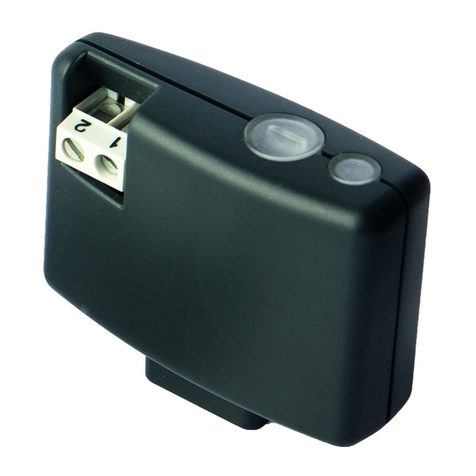
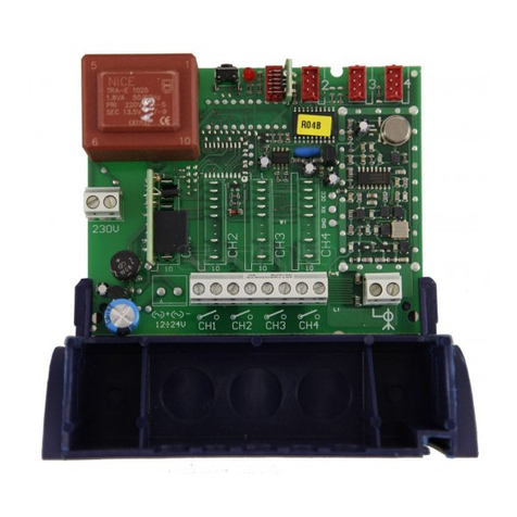
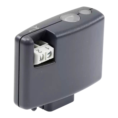
Wireless receiver for 1-10V
dimmable electronic power
TTD0110
EN - Instructions and warnings for installation and use
IT - Istruzioni ed avvertenze per l’installazione e l’uso
FR - Instructions et avertissements pour l’installation et l’utilisation
ES - Instrucciones y advertencias para la instalación y el uso
DE - Installierungs-und Gebrauchsanleitungen und Hinweise
PL -Instrukcjeiostrzeżeniadoinstalacjiiużytkowania
NL - Aanwijzingen en aanbevelingen voor installatie en gebruik


EN
English – 1
CONTENTS
1 GENERAL WARNINGS 1
2 PRODUCT DESCRIPTION AND INTENDED USE 2
3 ELECTRICAL CONNECTIONS 2
4 PROGRAMMING 4
4.1 “Slider” Function 5
4.2 LED 5
4.3 Transmitter recognition procedure 6
4.3.1 Using the “First Transmitter” (Empty Memory) 6
4.3.2 Using “Further Transmitters” Mode 1 7
4.3.3 Using “Further Transmitters” Mode 2 7
4.3.4 Using the “External Button” Mode 2 8
4.4 Memory deletion 9
4.4.1 Using the “Memorised Transmitter” 9
4.4.2 Using the “External Button” 9
4.5 Programming the brightness levels 10
4.5.1 Using the “Memorised Transmitter” 10
4.5.2 Using the “External Button” 11
4.6 Programming the locking and unlocking of the memory 11
4.6.1 Using the “Memorised Transmitter” 11
4.6.2 Using the “External Button” 12
5 Replacing a fuse 13
6 TECHNICAL SPECIFICATIONS 13
7 DISPOSAL OF THE PRODUCT 13
EC declaration of conformity 14
Instructions translated from Italian
ENGLISH 1 - GENERAL WARNINGS
• WARNING: Important safety instructions. Follow all instruc-
tions as improper installation may cause serious damage.
• ATTENTION: Important safety instructions. It is important for
you to comply with these instructions for your own and other
people’s safety. Keep these instructions.
• Children must not play with the appliance.
• Donotallowchildrentoplaywiththexedcontroldevicesofthe
product. Keep the remote controls away from children.
• Check the system frequently, especially check the wires for signs of
wear or damage. Do not use the device if it needs repair or adjust-
ment, because an installation failure can cause injury.
• Cleaning and maintenance that should be carried out by the user
must not be carried out by unsupervised children.
• ATTENTION: in order to avoid any danger due to inadvertent reset-
ting of the thermal cut-off device, this appliance must not be powered
through an external switching device, such as a timer, or connected
to a supply that is regularly powered or switched off by the circuit.
• Beforestartinginstallation,checkthe“Productspecications”(inthis
manual). If it is not suitable, DO NOT continue with the installation.
• The packing materials of the product must be disposed of in compli-
ance with local regulations.
• Before proceeding with the installation of the product, check that all
the materials are in good working order and suited to the intended
applications.
• The manufacturer assumes no liability for damage to property, items
or persons resulting from non-compliance with the assembly instruc-
tions. In such cases the warranty for material defects is excluded.
• Before working on the system (maintenance, cleaning), always dis-
connect the product from the mains power supply.
• Provide a disconnection device (not supplied) in the plant’s power sup-
ply grid, with a contact opening distance that permits complete discon-
nection under the conditions dictated by overvoltage category III.
• Handle the product with care during installation, taking care to avoid
crushing, denting or dropping it, or allowing contact with liquids of
any kind. Keep the product away from sources of heat and naked
ames.Failuretoobservetheabovecandamagetheproduct,and
EN
2– English
increase the risk of danger or malfunction. If this were to happen,
stop installation immediately and contact Customer Service.
2 - PRODUCT DESCRIPTION AND INTENDED USE
TTD0110 is a 1-10 Volt voltage regulator which drives the power out-
put of power supply units, with dimmer output, for lamps. Any other
use is improper and prohibited.
It is equipped with a radio receiver operating at a frequency of 433.92
MHz with “rolling code” encoding.
It can be controlled with Nice compatible products (Table 1) and with
an external push button to switch on and off and adjust the light inten-
sity of the lamp.
TABLE 1
Series Model Buttons Programming Function
Nice Era Era P Mode 1
(section 4)
Slider
(section 4)
Era W
Era MiniWay
Era One Mode 2
(section 4)
Era Inti
NiceWay NiceWay Mode 1
(section 4)
Nice Ergo Ergo
Nice Flor Flor-m Mode 2
(section 4)
Nice Very Very VR Mode 1
(section 4)
Nice
Home Touch HSTS2 display Mode 1
(section 4)
HSTX8 Mode 2
(section 4)
3 - ELECTRICAL CONNECTIONS
Special warnings:
• The product is subjected to hazardous voltage: therefore,
only open the housing and make connections with the power
switched off.
• Never cut the antenna cable, because it is subject to hazard-
ous voltage.
In order to make the electrical connections, you need to open the
TTD0110 (Fig. 1) and then proceed as shown in Fig. 2 and 3(complete
example of electrical connection):
1

EN
English – 3
2
112
ACNLAMP
V
V
+
-
+
-
DIM
DIM
ACL
L
P
N
2
3
4
5
6
7
3
supply voltage terminals
TTD0110 Input/Power
supply
220 - 240 Vac 7 - neutral N
6 - phase L
2 - earth T
External driver output/
power supply
5 - neutral N
4 - phase L
1 - earth T
Output/External button 3 - button P
7 - neutral N
low voltage terminals
Output/External driver:
adjustment 1-10 V or
0-10 V or 2-10 V or
PWM
dimmer connected to
power supply/driver 1 (-)
2 (+)
The product has two dip-switches (Fig. 4) that allow you to select the
type of load that will be connected to the output:

EN
4– English
112
2
3
4
5
6
7
1
ON
2
4
Dip 1 Dip 2 Description
Off Off Output 2-10 V
On Off Output 1-10 V
Off On Output 0-10 V
On On PWM (1k Hz)
Note:checkthetypeofloadinthetechnicalspecicationsofthede-
vice that is to be connected
4 - PROGRAMMING
The TTD0110 must be programmed with a transmitter memorised in
“Mode 1” or with the external button.
Up to 30 transmitters can be memorised in “Mode 1” or in “Mode 2”
in order to get different behaviours:
TABLE 2
Mode 1: automatically assign the three commands to the first three
buttons on the transmitter
Buttons Function
/ 1
2
3
4
Dimmer up
/
1
2
3
4
Toggle
/
1
2
3
4
Dimmer down
1
2
3
4... -
Mode 2: freely associate one command from among those available
Function Procedure Description
Dimmer up
1 short press
on the button
( < 1 second )
the brightness of the lamp increas-
es by a small percentage if it is not
already set to the maximum value
1 long press
on the button
( > 1 second )
the brightness of the lamp in-
creases until it reaches the maxi-
mum value set or until the button
is released
Toggle every time you
press the button
the dimmer turns the lamp On or
Off.
Brightness associated with “On”:
the last brightness value set on
the dimmer.
This value is memorised automati-
cally by the dimmer when the lamp
is switched off (i.e. the memorised
value will be the brightness of the
lamp before being switched off)
or, in any case, about 60 seconds
since the brightness was last ad-
justed (i.e. the last brightness value).
Dimmer down
1 short press
on the button
( < 1 second )
the brightness of the lamp decreas-
es by a small percentage if it is not
already set to the minimum value
1 long press
on the button
( > 1 second )
the brightness of the lamp de-
creases until it reaches the mini-
mum value set or until the button
is released
Dimmer up
Toggle
Dimmer down
...
every time you
press the button
the various functions are performed
alternately

EN
English – 5
4.1 - “Slider” Function
This allows you to turn the lamps On and Off and to adjust the bright-
ness dynamically. The capacitive strip acts like a slider:
Procedure Description
short touch on the slider absolute positioning command
sliding your nger on the
slider
progression of commands to adjust the
brightness dynamically: sending com-
mands regardless of where you place
your finger
4.2 - LED (Fig. 5)
The LED on the lower part of the TTD0110 sends various signals in the
programming procedures and some general signals:
Flashes Colour Execution Description
6green at the end of a
transmitter memori-
sation procedure
the memory is full:
the transmitter
cannot be memorised
2green when the dimmer is
powered
its memory is empty
(= no transmitter
memorised)
2red during any program-
ming procedure an error was
committed
on
fixed blue
it comes on when
the power supply
unit /driver is acti-
vated
voltage to terminals
5 and 4
5
In this manual the programming procedures are explained with the use
of icons and their meanings are shown in the table below:
KEY
LED: behaviour during the programming procedures
Symbol Description
ON
OFF
LONG ashing
SHORT ashing
FAST ashing
other symbols
Symbol Description
OFF
DISCONNECT POWER
LED red / green
LED blue

EN
6– English
ON
CONNECT POWER
LAMP ON
LAMP OFF
DESIRED VALUE
FOR THE BRIGHTNESS OF THE LAMP
PRESS BRIEFLY
PRESS AND HOLD THE BUTTON
ON THE TRANSMITTER
PRESS AND HOLD THE BUTTONS ON THE
TRANSMITTER AT THE SAME TIME
RELEASE THE BUTTON (OR THE BUT-
TONS) ON THE TRANSMITTER
---TRANSMITTER BUTTONS
1
2
3
4
-1
2
3
4
-
1
2
3
4
... TRANSMITTER BUTTONS
BRIEFLY PRESS THE DESIRED BUTTON
ON THE TRANSMITTER
PRESS AND HOLD THE DESIRED BUT-
TON ON THE TRANSMITTER
VIEW / SELECT
WAIT FOR...
2 seconds WAIT FOR A PRECISE TIME
BRIEFLY PRESS THE EXTERNAL BUTTON
PRESS AND HOLD THE EXTERNAL BUT-
TON
RELEASE THE EXTERNAL BUTTON
4.3 - Transmitter recognition procedure
4.3.1 - Using the “First Transmitter” (Empty Memory)
This procedure allows you to associate a transmitter to the dimmer in
“Mode 1”.
01.
OFF
2 seconds
ON
2
Green LED
02. within 5
seconds
for 8 seconds
03. 2green LED: memorising OK
2red LED: memorising NOT CONCLUDED
in this case, repeat the procedure from the beginning

EN
English – 7
4.3.2 - Using “Further Transmitters”: Mode 1
This procedure allows you to associate a transmitter to the dimmer in
“Mode 1”.
01. NEW
transmitter
for 8
seconds
1
red LED
02. OLD transmitter
already memorised x 3
03. NEW
transmitter
for 5 seconds
04. 2green LED: memorising OK
2red LED: memorising NOT CONCLUDED
in this case, repeat the procedure from the beginning
4.3.3 - Using “Further Transmitters”: Mode 2
This procedure allows you to associate a transmitter to the dimmer in
“Mode 2”.
01.
OLD
transmitter
already
memorised
for 8
seconds
1
green LED
02.
OLD
transmitter
already
memorised
for 8
seconds
2
green LED
03. OLD
transmitter
already memorised
select the desired function:
Dimmer Up > Toggle > Dimmer Down x 1
Dimmer Up x 2
Dimmer Down x 3
Toggle x 4
Level 1 x 5
Level 2 x 6
Level 3 x 7
Level 4 x 8
OFF x 9

EN
8– English
ON x 10
04.
5 seconds = ... green LED
no. of ... flashes according
to the chosen function
05. desire button on the
transmitter
green LED
3 sec. =
06. 2green LED: memorising OK
4.3.4 - Using “External Button”: Mode 2
This procedure allows you to associate a transmitter to the dimmer in
“Mode 2”.
01.
OFF
ON
green
LED
3 sec. =
02. green
LED 3 sec. =
at the the
03. select the desired function
Dimmer Up > Toggle > Dimmer Down x 1
Dimmer Up x 2
Dimmer Down x 3
Toggle x 4
Level 1 x 5
Level 2 x 6
Level 3 x 7
Level 4 x 8
OFF x 9
ON x 10
04.
5 seconds
green LED
no. of ... flashes according to
the chosen function
05. desire button on
the transmitter
green LED
3 sec. =
06. 2green LED: memorising OK

EN
English – 9
4.4 - Memory deletion
4.4.1 - Using “Memorised Transmitter”:
By using a transmitter memorised in “Mode 1”, you can fully or partially
delete the memory.
01.
1
green LED
02.
2
green LED
03.
3
green LED
04.
4
green LED
05.
select the desired function
Delete only the transmitters x 1
Delete only the parameters
x 1
Delete only the transmitters and
parameters
x 1
06. 5 seconds 2green LED
2red LED: memorising NOT CONCLUDED
in this case, repeat the procedure from the beginning
4.4.2 - Using “External Button”:
01.
OFF
ON
green
LED
3 sec. =
02. green
LED 3 sec. =
at the 2nd
03. green
LED 3 sec.= at the 5th
04. select the desired function

EN
10 – English
Delete only the transmitters x 1
Delete only the parameters x 2
Delete only the transmitters and param-
eters x 3
05. 5 seconds green LED
no. of ... flashes according to
the chosen function
06.
green LED
3 sec. =
07. 2green LED: memorising OK
4.5 - Programming the brightness levels
4.5.1 - Using “Memorised Transmitter”:
This procedure can only be done using a transmitter already memo-
rised in “Mode 1”.
The memorised brightness level can only be recalled after being as-
sociated with a transmitter button programmed in Mode 2.
01.
3 sec.
1
green
LED
02.
3 sec.
2
green
LED
03.
Use the
keys
p- q
to
adjust
brightness
desired light
intensity value
10
seconds
2
green
LED
04.
select the desired function
Level 1 =
2
green
LED
Level 2
=
2
green
LED
Level 3
=
2
green
LED
Level 4 =
2
green
LED

EN
English – 11
4.5.2 - Using “External Button”:
01.
OFF
ON
green
LED
3 sec. =
02. green
LED
3 sec. =
03. green
LED 3 sec. = at the 2nd
04. Adjusting the brightness of the lamp to the desired
value using the external push button:
1st long press on the external button
= increase in brightness until you release the button
2nd long press on the external button
= decrease in brightness until you release the button
CAUTION! = “Toggle” function (ON/OFF)
05. =
5 seconds
2+
desired light
intensity value
06.
select the desired level
Level 1 x 1
Level 2 x 2
Level 3 x 3
Level 4 x 4
07.
5 seconds green LED +
no. of ... flashes according to
the chosen level
08.
green LED
3 sec. =
09. 2green LED: memorising OK
4.6 - Programming the locking and unlocking of the memory
4.6.1 - Using “Memorised Transmitter”:
This procedure can only be done using a transmitter already memo-
rised in “Mode 1”.
01.
1green LED

EN
12 – English
02.
2green LED
03.
3green LED
04.
4green LED
05.
select the desired function
To lock
the
memory
2 ;
To
Unlock
the
memory
2 ;
4.6.2 - Using “External Button”:
01.
OFF
ON
green
LED 3 sec. =
02. green
LED 3 sec. =
at the 2nd
03. green
LED
3 sec. =
at the 2nd
04. select the desired function
To lock the memory x 1
To unlock the memory x 2
05.
5 seconds green LED +
no. of ... flashes according to
the chosen function
06.
green LED 3 sec. =
07. 2green LED: memorising OK

EN
English – 13
5 - Replacing a fuse
1
6 - TECHNICAL SPECIFICATIONS
Input
Voltage 230 Vac ± 10%
Frequency 50 Hz
Power consumption (standby) 550 mW
Output
Voltage 230 Vac ± 10%
Frequency 50 Hz
Maximum start-up current 80 A
Environment
Operating temperature -40 + 55° C
Storage temperature -40 + 70° C
IP 54
Dimensions 43 x 25 x 150 mm
Weight 100 g
7 - SCRAPPING THE PRODUCT
As in installation, also at the end of product lifetime, the disassembly and scrap-
ping operations must be performed by qualified personnel. This product is made
up of different types of material, some of which can be recycled while others
must be disposed of. Seek information on the recycling and disposal systems
envisaged by the local regulations in your area for this product category.
Caution! – some parts of the product may contain pollutant or hazardous sub-
stances which, if disposed of into the environment, may cause serious damage
to the environment or physical health.
As indicated by the symbol on the left, disposal of this product in
domestic waste is strictly prohibited. Separate the waste into cate-
gories for disposal, according to the methods envisaged by current
legislation in your area, or return the product to the retailer when
purchasing a new version.
Caution! – Local legislation may envisage serious fines in the event of abusive
disposal of this product. The packing materials of the product must be dis-
posed of in compliance with local regulations.

EN
14 – English
EC DECLARATION OF CONFORMITY
Declaration in compliance with Directive 1999/5/EC
Note – The content of this declaration corresponds to that specified in the official document depos-
ited at the Nice S.p.a. headquarters and, in particular, to the latest revised edition available prior to
the publishing of this manual. The text herein has been re-edited for editorial purposes. A copy of
the original declaration can be requested from Nice S.p.A. (TV) I.
Declaration number: 520/TTD0110 Revision: 0Language: EN
The undersigned, Mauro Sordini, CEO, declares under his sole responsibility that the
following product:
• Manufacturer's name: NICE S.p.A. • Address: Via Pezza Alta
No. 13, 31046 Rustignè di Oderzo (TV) Italy • Type of product: 1-10 V Radio receiver
for dimmable electronic power units • Model / Type: TTD0110 • Accessories: -
Complies with the essential requirements pursuant to Article 3 of the following Euro-
pean directive, relevant to the use for which the products are intended:
• DIRECTIVE 1999/5/EC OF THE EUROPEAN PARLIAMENT AND OF THE COUN-
CIL of 9 March 1999 on radio equipment and telecommunications terminal
equipment and the mutual recognition of their conformity, in accordance with the
following harmonised standards:
–Healthandsafety(Art.3(1)(a)):EN62479:2010
– Electrical safety (Art. 3(1)(a)): EN 60950-1:2006+A1:2010+A12:2011+A11:2009
+A2:2013
– Electromagnetic compatibility (Art. 3(1)(b)): EN 301 489-1 V1.9.2:2011, EN 301
489-3 V1.6.1:2013
– Radio spectrum (Art. 3(2)): EN 300 220-2 V2.4.1:2012
Moreover, the product complies with that specified in the following European direc-
tives:
Directive 2006/95/EC of the European Parliament and Council dated 12 December
2006 on the harmonisation of the laws of Member states relating to electrical
equipment designed for use within certain voltage limits, according to the follow-
ing harmonised regulations:
EN 60669-2-1:2004+A1:2009+A12:2010
• DIRECTIVE 2004/108/EC OF THE EUROPEAN PARLIAMENT AND COUNCIL of
15 December 2004 on the approximation of the laws of Member States relating to
electromagnetic compatibility and repealing Directive 89/336/EEC, in accordance
with the following harmonised standards:
EN 55015:2006+A1:2007+A2:2009, EN 61547:2009, EN 61000-3-2:2006+A1:20
09+A2:2009,EN61000-3-3:2013
Oderzo, 09 December 2014
Mr. Mauro Sordini
(Chief Executive Officer)

IT
Italiano – 1
SOMMARIO
1 AVVERTENZE GENERALI 1
2 DESCRIZIONE DEL PRODOTTO E DESTINAZIONE D’USO 2
3 COLLEGAMENTI ELETTRICI 2
4 PROGRAMMAZIONE 4
4.1 Funzione “Slider” 5
4.2 LED 5
4.3 Procedura di apprendimento Trasmettitori 6
4.3.1 Utilizzo “Primo Trasmettitore” (Memoria Vuota) 6
4.3.2 Utilizzo “Ulteriori Trasmettitori”: Modo 1 7
4.3.3 Utilizzo “Ulteriori Trasmettitori”: Modo 2 7
4.3.4 Utilizzo “Pulsante Esterno”: Modo 2 8
4.4 Cancellazione della Memoria 9
4.4.1 Utilizzo “Trasmettitore memorizzato” 9
4.4.2 Utilizzo “Pulsante Esterno” 9
4.5 Programmazione livelli di luminosità 10
4.5.1 Utilizzo “Trasmettitore memorizzato” 10
4.5.2 Utilizzo “Pulsante Esterno” 11
4.6 Programmazione blocco e sblocco della memoria 11
4.6.1 Utilizzo “Trasmettitore memorizzato” 11
4.6.2 Utilizzo “Pulsante Esterno” 12
5 Sostituzione fusibile 13
6 CARATTERISTICHE TECNICHE 13
7 SMALTIMENTO DEL PRODOTTO 13
Dichiarazione CE di conformità 14
Istruzioni originali e complete
ITALIANO 1 - AVVERTENZE GENERALI
• AVVERTENZA: Istruzioni importanti per la sicurezza. Seguire
tutte le istruzioni poiché l’installazione non corretta può cau-
sare gravi danni.
• ATTENZIONE: Importanti istruzioni di sicurezza. Per la sicu-
rezza delle persone è importante seguire queste istruzioni.
Conservare queste istruzioni.
• I bambini non devono giocare con l’apparecchio.
• Non permettere ai bambini di giocare con i dispositivi di comando
del prodotto. Tenere i telecomandi lontano dai bambini.
• Vericarefrequentementel’impianto,inparticolarecontrollareicavi,
segni di usura o danni. Non usare se è necessaria una riparazione
o una regolazione, poiché un guasto all’installazione può provocare
lesioni.
• La pulizia e la manutenzione destinata ad essere effettuata dall’utiliz-
zatore non deve essere effettuata da bambini senza sorveglianza.
• ATTENZIONE:alnedievitareognipericolodovutoalriarmoacci-
dentale del dispositivo termico di interruzione, questo apparecchio
non deve essere alimentato con un dispositivo di manovra esterno,
quale un temporizzatore, oppure essere connesso a un circuito che
viene regolarmente alimentato o disalimentato dal servizio.
• Primadiiniziarel’installazionevericarele“Caratteristichetecniche
del prodotto” (in questo manuale). Se non è adatto, NON procedere
all’istallazione.
• Il materiale dell’imballo del prodotto deve essere smaltito nel pieno
rispetto della normativa locale.
• Prima di procedere con l’installazione del prodotto, vericare che
tutto il materiale da utilizzare sia in ottimo stato ed adeguato all’uso.
• Il produttore non si assume alcuna responsabilità per danni patrimo-
niali, a cose o a persone derivanti dalla non osservanza delle istru-
zioni di montaggio. In questi casi è esclusa la garanzia per difetti
materiali.
• Prima degli interventi sull’impianto (manutenzione, pulizia), discon-
nettere sempre il prodotto dalla rete di alimentazione.
• Nella rete di alimentazione dell’impianto prevedere un dispositivo di
disconnessione (non in dotazione) con una distanza di apertura dei
contatti che consenta la disconnessione completa nelle condizioni

IT
2– Italiano
dettate dalla categoria di sovratensione III.
• Durante l’installazione maneggiare con cura il prodotto evitando
schiacciamenti, urti, cadute o contatto con liquidi di qualsiasi natura.
Nonmettereilprodottovicinoafontidicalore,néesporloaamme
libere. Tutte queste azioni possono danneggiarlo ed essere causa
di malfunzionamenti o situazioni di pericolo. Se questo accade, so-
spendere immediatamente l’installazione e rivolgersi al Servizio Assi-
stenza.
2 - DESCRIZIONE DEL PRODOTTO E DESTINAZIONE D’USO
TTD0110 è un regolatore di tensione 1-10 Volt che pilota l’uscita di
potenza di alimentatori/driver per la regolazione di sorgenti luminose.
Ogni altro uso è improprio e vietato.
È dotato di un ricevitore radio che opera alla frequenza di 433.92 MHz
con codifica “rolling code”.
Può essere comandato con i prodotti Nice compatibili (Tabella 1) e
con un pulsante esterno per accendere, spegnere e regolare l’intensità
luminosa della lampada.
TABELLA 1
Serie Modello Tasti Programmazione Funzionalità
Nice Era Era P Modo 1
(capitolo 4)
Slider
(capitolo 4)
Era W
Era MiniWay
Era One Modo 2
(capitolo 4)
Era Inti
NiceWay NiceWay Modo 1
(capitolo 4)
Nice Ergo Ergo
Nice Flor Flor-m Modo 2
(capitolo 4)
Ncice Very Very VR Modo 1
(capitolo 4)
Nice
Home Touch HSTS2 display Modo 1
(capitolo 4)
HSTX8 Modo 2
(capitolo 4)
3 - COLLEGAMENTI ELETTRICI
Avvertenze specifiche:
• Il prodotto è sottoposto a tensione elettrica pericolosa: l’a-
pertura del contenitore e tutti i collegamenti elettrici devono
essere eseguiti in assenza di tensione elettrica.
• Non tagliare per nessun motivo il cavo dell’antenna che è sot-
toposto a tensione elettrica pericolosa.
Per eseguire i collegamenti elettrici è necessario aprire TTD0110 (fig.
1) e poi procedere come mostrato in fig. 2 e3 (esempio di collega-
mento elettrico completo):
1

IT
Italiano – 3
2
112
ACNLAMP
V
V
+
-
+
-
DIM
DIM
ACL
L
P
N
2
3
4
5
6
7
3
tensione di rete morsetti
Ingresso / Alimentazio-
ne TTD0110
220 - 240 Vac 7 - neutro N
6 - fase L
2 - terra T
Uscita / Alimentazione
Driver esterno
5 - neutro N
4 - fase L
1 - terra T
Uscita / Pulsante ester-
no 3 - pulsante P
7 - neutro N
bassa tensione morsetti
Uscita / Driver esterno:
regolazione 1-10 V o
0-10 V o 2-10 V o PWM
dimmer connesso ad
alimentatore/driver 1 (-)
2 (+)
Il prodotto presenta due dip-switch (g. 4) che permettono di selezio-
nare il tipo di carico che verrà collegato all’uscita:

IT
4– Italiano
112
2
3
4
5
6
7
1
ON
2
4
Dip 1 Dip 2 Descrizione
Off Off Uscita 2-10 V
On Off Uscita 1-10 V
Off On Uscita 0-10 V
On On PWM (1k Hz)
Nota:vericarelatipologiadicariconellecaratteristichetecnichedel
dispositivo che verrà collegato.
4 - PROGRAMMAZIONE
La programmazione di TTD0110 deve essere eseguita con un trasmet-
titore memorizzato in “Modo 1” o con il pulsante esterno.
Possono essere memorizzati fino a 30 trasmettitori in “Modo 1” oppu-
re in “Modo 2” per ottenere comportamenti differenti:
TABELLA 2
Modo 1: assegnare automaticamente i tre comandi ai primi tre tasti
del trasmettitore
Tasti Funzione
/ 1
2
3
4
Dimmer up
/
1
2
3
4
Toogle
/
1
2
3
4
Dimmer down
1
2
3
4... -
Modo 2 : associare liberamente un comando tra quelli disponibili
Funzione Procedura Descrizione
Dimmer up
1 pressione
breve del tasto
( < 1 secondo )
la luminosità della lampada au-
menta di una piccola percen-
tuale se non è già impostata sul
valore massimo
1 pressione
prolungata del
tasto
( > 1 secondo )
la luminosità della lampada au-
menta no al raggiungimento
del valore massimo impostato
o al rilascio del tasto
Toogle ogni pressione del
tasto
il dimmer accende (On) o spe-
gne (Off) la sorgente luminosa
collegata.
Valore di luminosità associato
a “On”: ultima soglia di lumino-
sità memorizzata nel dimmer.
Il valore viene memorizzato
automaticamente dal dimmer
quando la lampada da accesa
viene spenta (in questo caso il
valore memorizzato sarà pari
alla luminosità della lampada
prima dello spegnimento) o
comunque dopo circa 60
secondi dall’ultima variazione
di luminosità (in questo caso
viene memorizzato l’ultimo
valore).
Dimmer down
1 pressione
breve del tasto
( < 1 secondo )
la luminosità della lampada
diminuisce di una piccola per-
centuale se non è già imposta-
ta sul valore minimo
Table of contents
Languages:
Other Nice Receiver manuals

Nice
Nice NiceOne OX4T Operating instructions

Nice
Nice NiceOne OXI/A Series Technical specifications

Nice
Nice HSTT2L User manual

Nice
Nice Home RC200 Technical specifications

Nice
Nice tt2d User manual

Nice
Nice RMF3004 User manual

Nice
Nice OXI Technical specifications

Nice
Nice elero Revio-868 SW User manual

Nice
Nice BIO Series User manual

Nice
Nice OXIBD User manual

Nice
Nice TT2Z Operating instructions

Nice
Nice FLOX1 User manual

Nice
Nice OXILR Technical specifications

Nice
Nice OXILR User manual

Nice
Nice FLOXMR Service manual

Nice
Nice NiceOne OX4 Product manual

Nice
Nice FLO Series User manual

Nice
Nice NICEONE OXI SERIES Product manual

Nice
Nice FLOX2R Installation manual

Nice
Nice elero Revio-868 SW User manual