Nice BiDi-Dimmer Technical specifications

EN - Instructions and warnings for installation and use
Bidirectional interface
for lights indoor
BiDi-Dimmer
Nice

1WARNINGS AND GENERAL PRECAUTIONS
• CAUTION! – This manual contains important instructions and warnings for personal safety. Carefully read all parts of this manual. If
in doubt, suspend installation immediately and contact the Nice Technical Assistance.
• CAUTION! – Important instructions: keep this manual in a safe place to enable future product maintenance and disposal pro-
cedures.
• CAUTION! – All installation and connection operations must be performed exclusively by suitably qualified and skilled person-
nel with the unit disconnected from the mains power supply.
• CAUTION! – Any use other than that specied herein or in environmental conditions other than those stated in this manual is
to be considered improper and is strictly forbidden!
• This product may only be used indoors or protected from weather conditions by control unit’s housing.
• The product’s packaging materials must be disposed of in full compliance with local regulations.
• Do not open the device protection housing as it contains non-serviceable electrical circuits.
• Never apply modifications to any part of the device. Operations other than those specified may only cause malfunctions. The manufacturer
declines all liability for damage caused by makeshift modifications to the product.
• Never place the device near to sources of heat and never expose to naked flames. These actions may damage the product and cause
malfunctions.
• This product is not intended for use by people (including children) with reduced physical, sensory or mental capabilities or who lack experi-
ence and knowledge, unless they have been given supervision or instruction concerning the use of the product by a person responsible for
their safety.
• Make sure that children do not play with the product.
• Check the warnings in the instruction manual for the light source that the product is connected to.
• Handle the product with care, being sure not to crush, knock or drop it in order to avoid damage.
2PRODUCT DESCRIPTION
The BiDi-Dimmer control unit enables the control of a single light source, mains powered. The light
source can be turned on/off and dimmed (if dimmable).
The control unit is equipped with an algorithm of a light source detection. It automatically selects suit-
able control mode and adjusts maximum and minimum light levels.
The BiDi-Dimmer control unit incorporates a radio transceiver that operates at the frequency of 433.92
MHz with rolling code technology to guarantee optimal safety levels.
Each control unit can memorise up to 30 mono or bidirectional transmitters in the series ERA, ERGO,
FLOR, NICEWAY and VERY, which enable the remote control of the unit.
The control unit is equipped with two inputs for controlling the unit by means of external switches.
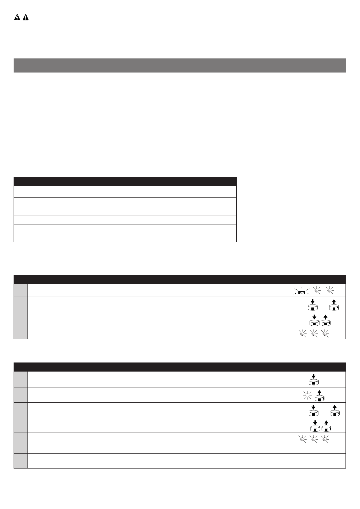
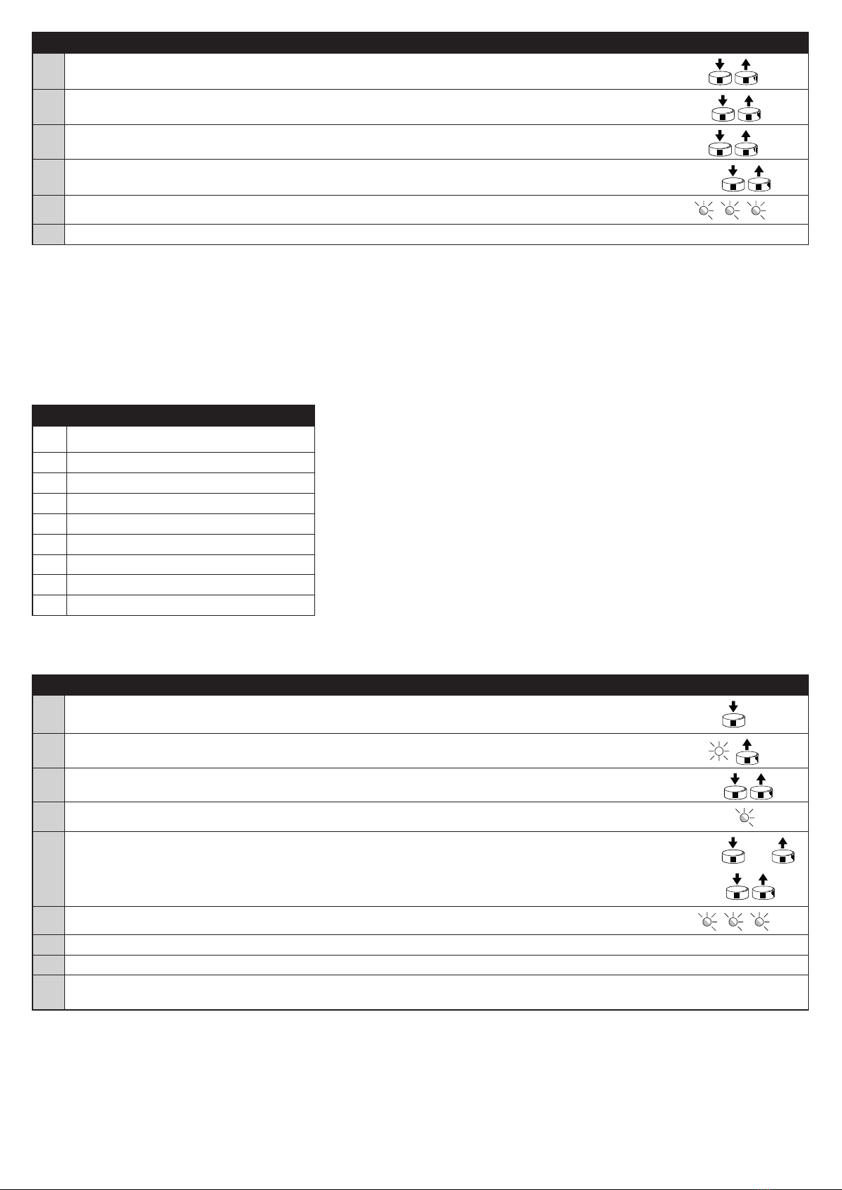
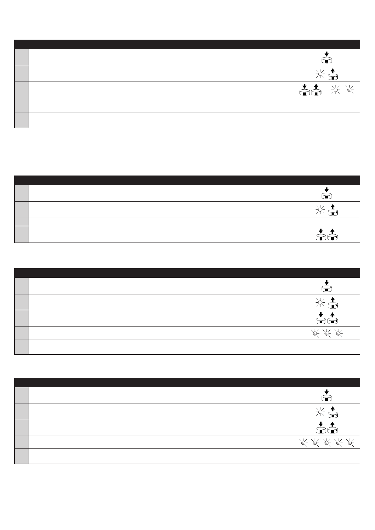
Memorisation and programming is possible via the programming pushbutton (gure 1) on the BiDi-Dimmer.
The user is guided through the various phases by means of LED signals.
The control unit is equipped with overload, and overheating protection, which will disable the load to
prevent damage to the circuit.
3INSTALLATION
• The product is subject to hazardous electric voltages
• The installation of the BiDi-Dimmer and automations must be performed exclusively by technically qualied personnel, in
observance of current legislation and standards, and according to these instructions. All connections must be made with
the system disconnected from the power supply.
• The BiDi-Dimmer control unit has been especially designed for insertion in a junction box or wall box; its housing does not
feature any protection against water and only basic protection against contact with solid parts. Never place the BiDi-Dim-
mer in inadequately protected environments.
• BiDi-Dimmer can work in 3-wire (with Neutral line) or 2-wire (without Neutral line) installation.
• Never open or perforate the BiDi-Dimmer housing, this is subject to hazardous electric voltages!
3.1 - Preliminary checks
• The power supply line must be protected by suitable magneto-thermal (compliant with IEC/EN 60898-1 standard, rated up to 16A) and
residual-current circuit breakers.
• A disconnection device must be inserted in the power supply line from the electrical mains (the distance between the contacts must be at
least 3mm with an overvoltage category of III) or equivalent system, for example an outlet and relative plug. If the disconnection device for
the power supply is not mounted near the automation, it must have a locking system to prevent unintentional, unauthorized connection.
3.2 - Electrical connections
Carefully follow all the connection instructions. If you have any doubts do not make experiments but consult the relevant
technical specications which are also available on the web site: www.niceforyou.com. An incorrect connection may be danger-
ous and cause damage to the system.
Programming
pushbutton
LED
1

3.3 - Light source
The light source to be controlled must be connected between neutral (N) and terminal ; the light source is powered directly by the control
unit.
Never connect more than one type of the light source per control unit!
3.4 - Power supply
The electric power supply of the control unit must be connected by means of terminals L and N (Live, Neutral) according to gure 2. If no Neu-
tral wire is present in the box, connect the N terminal with the Sx terminal according to gure 3. The BiDi-Dimmer control unit can operate with
supply voltage of 100 to 240 Volts and frequency of 50 or 60 Hz.
3.5 - Switches
If required, external switches can be connected to terminals S1 and S2, which can control the output directly. The switches are connected be-
tween Sx and terminals S1 and S2 as shown in gure 2 and 3. Toggle or momentary switches can be connected to S1 and S2 terminals, but
the operation of the control unit might need to be adjusted for the connected type of switch, to check and change the type of switch see table
A13. The response to the connected switches is as shown in the tables below (A1 for toggle switches, A2 for momentary switches).
Table A1 - Response to connected toggle switches (default)
Key Action Command
S1 single click if the lamp is >1% -> turn OFF the lamp
if the lamp is OFF -> set the last level
S2
single click if the lamp is >1% -> set the brightness to 30%
if the lamp is OFF -> set the brightness to the favourite level
double click if the lamp is >1% -> turn OFF the lamp
if the lamp is OFF -> turn ON the lamp to 100%
Table A2 - Response to connected momentary switches
Key Action Command
S1
single click if the lamp is >1% -> turn OFF the lamp
if the lamp is OFF -> set the last level
double click if the lamp is >1% -> set the lamp to 100%
if the lamp is OFF -> set the brightness to the favourite level
hold if the lamp is 100% -> start dimming down until released or until arrive at 0% (OFF)
if the lamp is 0-99% -> start brightening up until released or until arrive at 100% (ON)
S2
single click if the lamp is >1% -> set the brightness to 30%
if the lamp is OFF -> set the brightness to 70%
double click if the lamp is >1% -> turn OFF the lamp
if the lamp is OFF -> set the brightness to the favourite level
hold if the lamp is 100% -> start dimming down until released or until arrive at 0% (OFF)
if the lamp is 0-99% -> start brightening up until released or until arrive at 100% (ON)
2 3
3-wire installation (with Neutral) 2-wire installation (without Neutral)

The switches carry mains voltage and must therefore be adequately protected and insulated.
3.4 - LED Adaptor
The Nice LED Adaptor should be used in case of connecting LED bulbs or energy saving compact uorescent lamps. The LED Adaptor pre-
vents ickering of the LED lights and glowing of the turned off compact uorescent lamps. In the case of 2-wire connection, the LED Adaptor
allows to reduce minimum power of load required by the BiDi-Dimmer for correct operation. In such cases, connect the LED Adaptor in paral-
lel to the light source as shown in gure 2 and 3.
4MEMORISING TRANSMITTERS
• This chapter describes the memorisation procedures in Mode I, used to control a single automation with the 3 keys of the
transmitters and Mode II, used to control an automation with a single key, thus leaving the other keys free for control of
other automations.
• The key n corresponds to the central key of the transmitters ERGO, PLANO and NICEWAY.
• All memorisation sequences are timed, which means they must be completed within the set time limits.
• With transmitters that envisage several “groups”, the relative group to associate with the control unit must be selected
before proceeding.
• Settings via radio are possible on all receivers located within the operating radius of the transmitter, and therefore only the
device required for the operation should remain powered.
4.1 - Mode I
In Mode I the command associated with the transmitter keys is fixed (table A3). In Mode I only one memorisation phase is performed for each
transmitter and only one memory location is occupied. During memorisation in Mode I it is not important which key is pressed on the transmitter.
Table A3 - Memorisation using Mode I
Key Command
Key s or 1st channel Turn ON / Brighten UP (hold)
Key n or 2nd channel Toggle between OFF and the last level
Key t or 3rd channel Dimm OFF / Dimm down (hold)
Keys t + s or 1st + 3rd channels * Set favourite level (50% by default)
Slider (if equiped with) Set level
* Pressing two keys and the same time is not supported by some transmitters.
4.2 - Memorising transmitters in Mode I
When there is no transmitter memorised, the rst can be memorised during startup according to the following procedure.
Table A4 - Memorising rst transmitter during startup in Mode I Example
01. Connect the control unit to the power mains, conrmed by 2 red ashes.
02. Within 10 seconds:
• Monodirectional transmitters: press and hold any key of the transmitter to be memorized for at
least 3 seconds.
• Bidirectional transmitters: press any key of the transmitter to be memorized
MONO: 3s
BIDI:
03. If the memorisation procedure is successful, the LED emits 3 red ashes.
If no transmitters should be memorized during startup, the programming procedure concludes automatically after 10 seconds and the LED
emits one long red ash.
The transmitters can be memorised using the programming pushbutton according to the following procedure.
Table A5 - Memorising rst and other transmitters in Mode I Example
01. Press and hold the programming pushbutton.
02. Release the programming pushbutton when the LED illuminates with red color (1st position).
03. Within 10 seconds:
• Monodirectional transmitters: press and hold any key of the transmitter to be memorized for at
least 3 seconds.
• Bidirectional transmitters: press any key of the transmitter to be memorized
MONO: 3s
BIDI:
04. If the memorisation procedure is successful, the LED emits 3 red ashes.
05. Repeat steps 3 and 4 to acquire all the remotes.
06. After 10 seconds that the device doesn’t receive any signal, the programming procedure concludes auto-
matically.
If transmitters have already been memorised, other transmitters can be memorised as described in the following procedure.

Table A6 - Memorising other transmitters with a previously memorised transmitter in Mode I Example
01. Press any key three times of a previous, memorised transmitter. Old x3
02. Press the same key three times of a new transmitter. New x3
03. Press the same key three times of a previous, memorised transmitter. Old x3
04. Press the same key of the new transmitter. New
05. If the memorisation procedure is successful, the LED emits 3 red ashes.
06. The programming procedure concludes automatically.
Note. If the memory is full (30 transmitters memorised) 6 red flashes are emitted and the transmitter cannot be memorised.
4.3 - Mode II
In Mode II each key of the transmitter can be associated with one of 8 possible commands (table A7); for example, one automation can be
controlled with just one key memorised for the toggle command, while the other keys are left free for control of other automations. In Mode II
one memorisation phase is performed for each key and each occupies one location in the memory. During Mode II memorisation, the specific
key pressed is memorised. If another key is to be assigned a command on the same transmitter, a new memorisation phase must be performed
for that specific key.
Warning! - For the partial positions to work correctly, you must perform the calibration procedure (see chapter 5.1).
Table A7 - Memorisation using Mode II
Nº Command
1 Turn ON / Brighten UP (hold) *
2 Dimm OFF / Dimm down (hold) *
3 Toggle between OFF and the last level
4 OFF
5 Set 25%
6 Set 50%
7 Set 75%
8 ON
* Holding a key is not supported by some transmitters.
4.4 - Memorising transmitters in Mode II
Table A8 - Memorising rst and other transmitters in Mode II Example
01. Press and hold the programming pushbutton.
02. Release the programming pushbutton when the LED illuminates with orange color (2nd position).
03. Press the programming pushbutton the number of times corresponding to the required command
(1 = brighten, 2 = dimm, 3 = toggle, 4 = OFF, 5 = set 25%, 6 = set 50%, 7 = set 75%, 8 = ON). 1-8
04. Check that the LED emits the number of long orange ashes corresponding to the required command. 1-8
05. Within 10 seconds:
• Monodirectional transmitters: press and hold the required key of the transmitter to be memorized
for at least 3 seconds.
• Bidirectional transmitters: press the required key of the transmitter to be memorized
MONO: 3s
BIDI:
06. If the memorisation procedure is successful, the LED emits 3 orange ashes.
07. Repeat steps 5 and 6 to acquire all the remotes with the same command.
08. Repeat steps 3 to 6 to acquire all the remotes with another command.
09. After 10 seconds that the device doesn’t receive any signal, the programming procedure concludes auto-
matically.
Note. If the memory is full (30 transmitters memorised) 6 orange flashes are emitted and the transmitter cannot be memorised.

4.5 - Memorising a new transmitter using the “enabling code” of an already memorised transmitter
The bidirectional transmitter has a secret code, the so-called “enabling code”. By transferring this code from a memorized transmitter to a new
transmitter, the latter is recognized (and memorized) automatically by the control unit.
Warning! - The enabling code can only be transferred between two transmitters that have the same radio coding.
Table A9 - Transmitting the “enabling code” Example
01. Bring a previous, memorised transmitter and the new transmitter close to one another.
02. On the new transmitter press command key. The LED of the previous transmitter will switch on and start
ashing. New Old
03. On the previous transmitter press command key. Old
04. Once the code has been transferred, for an instant both the transmitters will vibrate and the green LED will
light up signalling end of the procedure.
When the new transmitter will be used, for the rst 20 times it will transmit this “enabling code” to the
receiver together with the command. The receiver will automatically memorize the identication code of the
transmitter that transmitted it
5SETTINGS
5.1 - Calibration
The control unit is equipped with an algorithm for light source detection. It automatically selects a suitable control mode and adjusts maximum
and minimum light levels.
If the calibration procedure was not performed, the control unit will perform the autocalibration the first time it recognizes a load.
The calibration process can be performed in two ways, with a pushbutton (Table A10) or with the bound transmitter (Table A11).
Table A10 - Calibration with a pushbuton Example
01. Press and hold the programming pushbutton.
02. Release the programming pushbutton when the LED illuminates with blue color (3rd position).
03. Press the key n(or second channel) of the transmitter to start the 1st method of calibration (without LED
Adaptor) or press the key t(or third channel) to start the 2nd method of calibration (with LED Adaptor).
04. The control unit will perform the calibration, the load might blink and change the brightness level. The load
will be switched off once the process is completed.
05. The programming procedure concludes automatically.
Table A11 - Calibration with a bound transmitter Example
01. Press the PRG pushbutton on the bound transmitter.
02. Release the PRG pushbutton when the connected load blinks.
03. Press the key n(or second channel) of the transmitter to start the 1st method of calibration (without LED
Adaptor) or press the key t(or third channel) to start the 2nd method of calibration (with LED Adaptor). /
04. The control unit will perform the calibration, the load might blink and change the brightness level. The load
will be switched off once the process is completed.
05. The programming procedure concludes automatically.
Note. After the calibration, the favourite position is reset to the default value.
5.2 - Auto OFF
This function allows to automatically turn OFF the load when saved time passes from turning ON. By default, the Auto OFF function is disa-
bled. To set Auto OFF time or disable the function, proceed as described below.
Table A12 - Setting auto OFF for output 1 Example
01. Press and hold the programming pushbutton (g. 1).
02. Release the programming pushbutton (g. 1) when the LED illuminates with green color (4th position).
03. If you want to disable the auto OFF function, wait 10 seconds, so the programming procedure concludes
automatically.
04. Press the transmitter’s key responsible for brightening UP the rst output to start the timer. > START
05. Press the transmitter’s key responsible for dimming OFF the rst output to stop the timer.
The maximum time that can be set is 9 hours. > STOP
06. The auto OFF time is saved and the programming procedure concludes automatically.

5.3 - Type of connected switches
The control unit allows to connect momentary or toggle switches to S1 and S2 input. By default, the toggle switch type is set.
To change type of connected switch, proceed as described below.
Table A13 - Setting type of connected switches Example
01. Press and hold the programming pushbutton.
02. Release the programming pushbutton when the LED illuminates with violet color (5th position).
03. Press key of the transmitter responsible for turning ON to toggle the setting, the LED informs about current
setting:
• Fixed white – momentary switch
• Flashing white – toggle switch
> /
04. After 10 seconds that the device doesn’t receive any signal, the programming procedure concludes auto-
matically.
5.4 - Favourite brightness level
The control unit enables setting a quickly accessible favourite brightness level. Favourite level works only with transmitters memorized in Mode
I. To recall the favourite brightness level: press s and tor 1st and 3rd channel at the same time. In order for this function to work, the
load must be calibrated. By default, the favourite brightness level is set to 50%.
To set new favourite brightness level, proceed as described below.
Table A14 - Setting partial position Example
01. Press and hold the programming pushbutton.
02. Release the programming pushbutton when the LED illuminates with white color (6th position).
03. Bring the light at your desired brightness level
04. Save and conclude the programming by pushing the programming pushbutton.
5.5 - Deleting transmitters
If memorised transmitters and settings need to be deleted, proceed as described below.
Table A15 - Deleting transmitter from memory Example
01. Press and hold the programming pushbutton.
02. Release the programming pushbutton when the LED illuminates with yellow color (7th position).
03. Press any button on the acquired transmitter to remove it from memory.
04. LED emits 3 yellow ashes to conrm the correct removal.
05. After 10 seconds that the device doesn’t receive any signal, the programming procedure concludes auto-
matically.
5.6 - Factory reset
If the control unit needs to be reset to the factory settings (all transmitters and settings will be deleted), proceed as described below.
Table A16 - Restoring to factory defaults Example
01. Press and hold the programming pushbutton.
02. Release the programming pushbutton when the LED illuminates with yellow color (7th position).
03. Press the programming pushbutton.
04. LED emits 5 yellow ashes to conrm the correct reset.
05. The programming procedure concludes automatically.
Afterwards the control unit will initiate the start-up procedure according to table A4.

6LED SIGNALS
6.1 - Programming menu
When pressing and holding the programming pushbutton on the control unit, the LED will signal consecutive positions of the programming menu.
Table A17 - menu positions when holding the programming pushbutton
Nº Color Description
1 Red Memorization in Mode I
2 Orange Memorization in Mode II
3 Blue Calibration
4 Green Auto OFF settings
5 Violet Switch type settings
6 White Favourite brightness level settings
7 Yellow Reset
6.2 - Other signals
Table A18 - other LED signals
Color Description
2 red ashes No transmitters memorized
3 red ashes Transmitter memorized in Mode I
3 orange ashes Transmitter memorized in Mode II
6 red ashes Memory for transmitters full (Mode I)
6 orange ashes Memory for transmitters full (Mode II)
3 yellow ashes Transmitter deleted from memory
5 yellow ashes Control unit restored to factory settings
7TECHNICAL SPECIFICATIONS
The product BiDi-Dimmer is produced by Nice S.p.a. (TV). Warnings: - All technical specifications stated in this section refer to an ambient
temperature of 20 °C (± 5 °C) - Nice S.p.a. reserves the right to apply modifications to the product at any time when deemed necessary, while
maintaining the same functionalities and intended use.
BiDi-Dimmer
Type in-wall/ush box mounted control unit for single light source
Power supply 100–240 V AC, 50/60 Hz
Rated current 1.1 A
Rated power Resistive loads (incandescent and halogen):
50–250 W for Vn =240 V; 25–125 W for Vn = 120 V
Resistive-capacitive loads (uorescent tube lamp, electronic transformer, LED):
50–200 VA for Vn =240 V; 25–100 VA for Vn = 120 V
Resistive-inductive loads (ferromagnetic transformers):
50–220 VA for Vn =240 V; 25–110 VA for Vn = 120 V
Rated power
with connected Nice LED Adaptor
Resistive-capacitive loads (uorescent tube lamp, electronic transformer, LED):
5–200 VA for Vn =240 V; 5–100 VA for Vn = 120 V
Recommeded wires cross-section 0.5–4 mm2for 1 wire; 0.5–1.5 mm2for 2 wires
Required circuit breaker Compliant with IEC/EN 60898-1; Curve code: B; Rated current: up to 16 A;
Breaking capacity: 6 kA; Rated insulation voltage: 500 V;
Rated impulse withstand voltage: 4 kV;
Casing protection rating IP 20
Operating temperature 0–35 °C
Dimensions (mm) 45 x 36 x h 23
Weight 34 g

Radio transceiver
Frequency band 433.05–434.04 MHz
Code OPERA/FLOR (rolling code), PLN2+ (rolling code)
No. of memorisable transmitters 30
Transceiver range Estimated at 150 m in open space and 20 m inside buildings (*)
Max. transmit power 10 dBm
(*) The transceiver range is strongly inuenced by other devices operating at the same frequency with continuous transmission, such as alarms
and radio headphones which interfere with the control unit transceiver.
8PRODUCT DISPOSAL
This product is an integral part of the automation and therefore must be disposed together with the latter.
As in installation, also at the end of product lifetime, the disassembly and scrapping operations must be performed by qualified personnel. This
product is made of various types of material, some of which can be recycled while others must be scrapped. Seek information on
the recycling and disposal systems envisaged by the local regulations in your area for this product category.
Caution! – some parts of the product may contain pollutant or hazardous substances which, if disposed of into the environment,
may cause serious damage to the environment or physical health.
As indicated by the symbol alongside, disposal of this product in domestic waste is strictly prohibited. Separate the waste into
categories for disposal, according to the methods envisaged by current legislation in your area, or return the product to the retailer
when purchasing a new version.
Caution! – local legislation may envisage serious fines in the event of abusive disposal of this product.
9DECLARATION OF CONFORMITY
Hereby, NICE S.p.A., declares that the radio equipment type BiDi-Dimmer is in compliance with Directive 2014/53/EU.
The full text of the EU declaration of conformity is available at the following internet address: http://www.niceforyou.com/en/support
Table of contents
Other Nice Recording Equipment manuals

Nice
Nice BiDi-WiFi Product manual

Nice
Nice IT4WIFI Technical specifications

Nice
Nice IBT4N Technical specifications

Nice
Nice IT4WIFI Technical specifications

Nice
Nice O-Box Product manual

Nice
Nice BusT4 Technical specifications

Nice
Nice Pro-View User manual

Nice
Nice Core User manual

Nice
Nice RS485 User manual

Nice
Nice BiDi-Shutter Technical specifications