Nicotra Gebhardt AT Series Manual

CENTRIFUGAL FANS
VENTILATORI CENTRIFUGHI
RADIAL-VENTILATOREN
VENTILATEURS CENTRIFUGES
VENTILADORES CENTRÍFUGOS
SERIES - SERIE - SERIEN - SÉRIE - SERIE
AT-AS-ASH-RSH-ADH-ADH-E-RDH-RDH-E
INSTALLATION AND MAINTENANCE MANUAL
MANUALE USO E MANUTENZIONE
GEBRAUCHS- UND WARTUNGSANLEITUNGEN
MANUEL D’UTILISATION ET MAINTENANCE
MANUAL DE USO Y MANTENIMIENTO
Regal Beloit Italy S.p.A. Sede Legale: Viale Luigi Majno 26 - 20129 Milano - Italia e-mail: info@nicotra-gebhardt.com
Società Soggetta a Direzione e Coordinamento di Regal Beloit Co. (USA)
Stabilimento, uffici amministrativi e commerciali: 24040 Ciserano Loc. Zingonia (BG) - Via Modena, 18 - Tel. 035-873111 - Fax 035-884319
❒Fans in accordance with ATEX directive - Declaration of conformity at the end of this manual
❒Ventilatori conformi alla direttiva ATEX - Dichiarazione di conformità in fondo a questo manuale
❒Ventilatoren gemäß der ATEX-Richtlinie - Konformitätserklärung am Ende dieses Anleitungen
❒Ventilateurs conformes à la directive ATEX - Déclaration de conformité à la fin de ce manuel
❒Ventiladores conforme a la directiva ATEX - Declaración de conformidad al final de este manual
COD. 985719/12 - 10-2020

COD. 985719/12 - 10-2020
SUMMARY
1. GENERAL INFORMATION........ 6
1.1 ATEX VERSIONS..........................6
2. RECEIVING AND INSPECTING
THE PRODUCT........................ 6
2.1 DATA ON THE RATING PLATE .... 8
2.2 WEIGHTS OF THE PRODUCT .. 10
2.3 HANDLING AND LIFTING THE FAN 10
2.4 STORAGE .................................. 12
3. FUNCTION AND DESIGN
OF THE FAN........................... 14
3.1 OPERATING CONDITIONS ....... 14
3.2 OPERATING LIMITS................... 14
3.2.1. Max. installed power.................. 14
3.2.2. Maximum speed ....................... 14
3.2.3. Operating temperature ............. 14
3.3 BALANCING .............................. 16
3.4 BEARINGS.................................. 16
3.4.1. Bearing life ................................ 16
3.5 SHAFTS...................................... 16
4. INSTALLATION ....................... 16
4.1 FIXING THE FAN ........................ 18
4.2 INSTALLING THE DRIVE
SYSTEM ..................................... 20
4.2.1. Problems due to a too low
belt tension................................ 22
4.2.2. Problems due to a too high
belt tension................................ 22
4.2.3. Belt tension .............................. 22
4.3 SAFETY ACCESSORIES .......... 24
4.3.1. Protection of moving
components............................... 24
4.3.2. Electrical insulation ................... 24
4.4 INSPECTION
AFTER INSTALLATION............... 24
4.5 STARTING THE FAN................... 26
5. MAINTENANCE....................... 26
5.1 ORDINARY MAINTENANCE ..... 28
5.1.1. ATEX version............................. 28
5.1.2. Drive.......................................... 28
5.1.3. Bearings ................................... 30
5.1.4. Bearings lubrication .................. 30
SOMMARIO
1. INTRODUZIONE........................ 6
1.1 VERSIONI ATEX............................6
2. RICEVIMENTO E ISPEZIONE..... 6
2.1 DATI ETICHETTA ...................... 8
2.2 PESI DEI PRODOTTI ................. 10
2.3 MOVIMENTAZIONE ................... 10
2.4 STOCCAGGIO ........................... 12
3. CARATTERISTICHE DEL
VENTILATORE....................... 14
3.1 CONDIZIONI OPERATIVE ......... 14
3.2 LIMITI DI IMPIEGO..................... 14
3.2.1. Potenza massima da installare ... 14
3.2.2. Velocità massima ..................... 14
3.2.3. Temperatura dell’aria ................ 14
3.3 EQUILIBRATURA ....................... 16
3.4 CUSCINETTI............................... 16
3.4.1. Durata dei cuscinetti.................. 16
3.5 ALBERI ....................................... 16
4. INSTALLAZIONE..................... 16
4.1 FISSAGGIO DEL VENTILATORE . 18
4.2 INSTALLAZIONE DELLA
TRASMISSIONE......................... 20
4.2.1. Problemi dovuti ad una
insufficiente tensione
delle cinghie .............................. 22
4.2.2. Problemi dovuti ad una
eccessiva tensione
delle cinghie .............................. 22
4.2.3. Misura della tensione
delle cinghie ............................. 22
4.3 ACCESSORI DI SICUREZZA .... 24
4.3.1. Protezione degli organi
in movimento............................. 24
4.3.2. Dispositivo di blocco
dell’alimentazione...................... 24
4.4 OPERAZIONI DI CONTROLLO
A FINE INSTALLAZIONE............ 24
4.5 AVVIO DEL VENTILATORE ........ 26
5. MANUTENZIONE .................... 26
5.1 MANUTENZIONE ORDINARIA . 28
5.1.1. Versioni ATEX ........................... 28
5.1.2. Trasmissione ............................. 28
5.1.3. Cuscinetti ................................. 30
5.1.4. Lubrificazione dei cuscinetti ...... 30
2

COD. 985719/12 - 10-2020
3
INHALTSVERZEICHNIS
1. EINFÜHRUNG ........................... 7
1.1 ATEX-VERSIONEN .......................7
2. ANNAHME UND KONTROLLE .. 7
2.1 ETIKETTANGABEN ................... 9
2.2 PRODUKTGEWICHTE .............. 11
2.3 HANDHABUNG .......................... 11
2.4 AUFBEWAHRUNG ..................... 13
3. VENTILATOR-
EIGENSCHAFTEN................. 15
3.1 ARBEITSBEDINGUNGEN ......... 15
3.2 EINSATZGRENZWERTE............ 15
3.2.1. Max. Antriebsleistung ................ 15
3.2.2. Max. zulässige Drehzahl .......... 15
3.2.3. Lufttemperatur .......................... 15
3.3 AUSWUCHTUNG ....................... 17
3.4 LAGER ........................................ 17
3.4.1. Lagerlebensdauer ..................... 17
3.5 WELLEN ..................................... 17
4. MONTAGE ............................... 17
4.1 VENTILATORBEFESTIGUNG .... 19
4.2 ANTRIEBS-
INSTALLATION ........................... 21
4.2.1. Durch eine unzureichende
Riemenspannung
verursachte Probleme ............... 23
4.2.2. Durch eine übermäßige
Riemenspannung
verursachte Probleme ............... 23
4.2.3. Messen der
Riemenspannung...................... 23
4.3 SICHERHEITSZUBEHÖRTEILE 25
4.3.1. Schutzvorrichtung
für laufende Teile ...................... 25
4.3.2. Blockiervorrichtung
für die Stromversorgung ........... 25
4.4 KONTROLLEN
NACH DER MONTAGE .............. 25
4.5 VENTILATOR-
INBETRIEBNAHME...................... 27
5. WARTUNG .............................. 27
5.1 ORDENTLICHE WARTUNG ...... 29
5.1.1. ATEX-Versionen ....................... 29
5.1.2. Antrieb ...................................... 29
5.1.3. Lager ........................................ 31
5.1.4. Schmierung der Lager .............. 31
SOMMAIRE
1. INTRODUCTION........................ 7
1.1 VERSIONS ATEX ..........................7
2. RÉCEPTION ET INSPECTION ... 7
2.1 DONNÉES DE L’ÉTIQUETTE ..... 9
2.2 POIDS DES PRODUITS ............ 11
2.3 MOUVEMENT ............................ 11
2.4 STOCKAGE ............................... 13
3. CARACTÉRISTIQUES DU
VENTILATEUR....................... 15
3.1 CONDITIONS DE TRAVAIL ....... 15
3.2 LIMITATIONS D’EMPLOI ............ 15
3.2.1. Puissance maximum à installer . 15
3.2.2. Vitesse maximum ..................... 15
3.2.3. Température de l’air ................. 15
3.3 ÉQUILIBRAGE ........................... 17
3.4 PALIERS .................................... 17
3.4.1. Durée des paliers ..................... 17
3.5 ARBRES .................................... 17
4. INSTALLATION ....................... 17
4.1 FIXAGE DU VENTILATEUR ........ 19
4.2 INSTALLATION DE LA
TRANSMISSION......................... 21
4.2.1. Problèmes dus à une
insuffisante tension
des courroies ............................ 23
4.2.2. Problèmes dus à une
excessive tension
des courroies............................. 23
4.2.3. Mesure de la tension
des courroies ............................ 23
4.3 ACCESSOIRES DE SÉCURITÉ 25
4.3.1. Protection des organes
en mouvement ......................... 25
4.3.2. Dispositif de bloc
de l’alimentation ....................... 25
4.4 OPÉRATIONS DE CONTRÔLE
EN FIN D’INSTALLATION ........... 25
4.5 DÉMARRAGE DU
VENTILATEUR............................ 27
5. MAINTENANCE....................... 27
5.1 MAINTENANCE ORDINAIRE .... 29
5.1.1. Versions ATEX .......................... 29
5.1.2. Transmission ............................ 29
5.1.3. Paliers ...................................... 31
5.1.4. Lubrification des paliers ............ 31
ÍNDICE
1. INTRODUCCIÓN ....................... 7
1.1 VERSIONES ATEX .......................7
2. RECEPCIÓN E INSPECCIÓN..... 7
2.1 DATOS DE LA ETIQUETA .......... 9
2.2 PESOS DE LOS PRODUCTOS 11
2.3 TRASLADO ................................ 11
2.4 ALMACENAMIENTO................... 13
3. CARACTERÍSTICAS DEL
VENTILADOR ........................ 15
3.1 CONDICIONES OPERATIVAS ... 15
3.2 LÍMITES DE USO ....................... 15
3.2.1. Potencia máxima a instalar......... 15
3.2.2. Velocidad máxima .................... 15
3.2.3. Temperatura del aire ................ 15
3.3 EQUILIBRACIÓN ....................... 17
3.4 RODAMIENTOS ......................... 17
3.4.1. Duración de los rodamientos ... 17
3.5 EJES .......................................... 17
4. INSTALACIÓN ......................... 17
4.1 FIJACIÓN DEL VENTILADOR .... 19
4.2 INSTALACIÓN DE LA
TRANSMISIÓN ........................... 21
4.2.1. Problemas causados por
insuficiente tensión
de las correas ........................... 23
4.2.2. Problemas causados por
excesiva tensión
de las correas............................ 23
4.2.3. Medida de la tensión
de las correas ........................... 23
4.3 ACCESORIOS DE SEGURIDAD 25
4.3.1. Protección de los órganos
en movimiento .......................... 25
4.3.2. Dispositivo de bloqueo
de la alimentación .................... 25
4.4 OPERACIONES DE CONTROL
AL FINALIZAR LA INSTALACIÓN . 25
4.5 PUESTA EN MARCHA DEL
VENTILADOR ............................. 27
5. MANTENIMIENTO................... 27
5.1 MANTENIMIENTO ORDINARIO 29
5.1.1. Versiones ATEX ........................ 29
5.1.2. Transmisión ............................... 29
5.1.3. Rodamientos ............................ 31
5.1.4. Lubricación de los rodamientos 31

4
COD. 985719/12 - 10-2020
5.2 REPLACING INSTRUCTIONS
FOR BEARINGS.......................... 38
5.2.1. Dismantling the bearing with
eccentric locking collar.............. 38
5.2.2. Mounting the bearing with
eccentric locking collar.............. 38
5.2.3. Dismantling the plummer block
with ball bearing and
eccentric locking collar ............. 40
5.2.4. Mounting the plummer block
with ball bearing and
eccentric locking collar ............. 40
5.2.5. Dismantling the plummer block
with ball bearing and
adapter sleeve .......................... 40
5.2.6. Mounting the plummer block
with ball bearing and
adapter sleeve .......................... 42
5.2.7. Dismantling the SNL plummer
block with self-aligning
ball bearing and
adapter sleeve .......................... 44
5.2.8. Mounting the SNL plummer
block with self-aligning
ball bearing and
adapter sleeve .......................... 44
5.2.9. Dismantling ConCentra
roller bearing ............................ 52
5.2.10.Mounting ConCentra
roller bearing ............................ 54
AT “ATEX” OPERATING LIMITS ......... 58
ASH “ATEX” OPERATING LIMITS ...... 59
RSH “ATEX” OPERATING LIMITS ...... 60
ADH “ATEX” OPERATING LIMITS ...... 61
ADH-E “ATEX” OPERATING LIMITS .. 62
RDH “ATEX” OPERATING LIMITS ...... 63
RDH-E “ATEX” OPERATING LIMITS .. 64
6. DECLARATION
OF CONFORMITY - ATEX..... 67
DECLARATION
OF INCORPORATION .......... 67
5.2 SOSTITUZIONE DEI
CUSCINETTI............................... 38
5.2.1. Smontaggio dei cuscinetti
con collare eccentrico
di fissaggio ................................ 38
5.2.2. Montaggio dei cuscinetti
con collare eccentrico
di fissaggio ................................ 38
5.2.3. Smontaggio dei supporti con
cuscinetto a sfere e collare
eccentrico di fissaggio .............. 40
5.2.4. Montaggio dei supporti con
cuscinetto a sfere e collare
eccentrico di fissaggio .............. 40
5.2.5. Smontaggio dei supporti con
cuscinetto a sfere e fissaggio
con bussola di trazione ............ 40
5.2.6. Montaggio dei supporti con
cuscinetto a sfere e fissaggio
con bussola di trazione ............ 42
5.2.7. Smontaggio dei supporti tipo
SNL con cuscinetto a doppia
corona di sfere e fissaggio
con bussola di trazione ............ 44
5.2.8. Montaggio dei supporti tipo
SNL con cuscinetto a doppia
corona di sfere e fissaggio
con bussola di trazione ............ 44
5.2.9. Smontaggio sopporti SKF
ConCentra a rulli ...................... 52
5.2.10.Montaggio sopporti SKF
ConCentra a rulli ...................... 54
AT “ATEX” LIMITI DI IMPIEGO .......... 58
ASH “ATEX” LIMITI DI IMPIEGO ....... 59
RSH “ATEX” LIMITI DI IMPIEGO ....... 60
ADH “ATEX” LIMITI DI IMPIEGO .......... 61
ADH-E “ATEX” LIMITI DI IMPIEGO ....... 62
RDH “ATEX” LIMITI DI IMPIEGO .......... 63
RDH-E “ATEX” LIMITI DI IMPIEGO ....... 64
6. DICHIARAZIONE
DI CONFORMITA’ - ATEX...... 65
DICHIARAZIONE
DI INCORPORAZIONE.......... 65

5
COD. 985719/12 - 10-2020
5.2 AUSWECHSELN
DER LAGER .............................. 39
5.2.1. Ausbauen der Lager
mit exzentrischer
Befestigungsschelle ................. 39
5.2.2. Einbauen der Lager
mit exzentrischer
Befestigungsschelle ................. 39
5.2.3. Ausbauen der Halter mit
Kugellager und exzentrischer
Befestigungsschelle ................. 41
5.2.4. Einbauen der Halter mit
Kugellager und exzentrischer
Befestigungsschelle ................. 41
5.2.5. Ausbauen der Halter mit
Kugellager und
Reduziereinsatzbefestigung ..... 41
5.2.6. Einbauen der Halter mit
Kugellager und
Reduziereinsatzbefestigung ..... 43
5.2.7. Ausbauen der SNL-Halter
mit doppelreihigem
Kugellager und
Reduziereinsatzbefestigung ..... 45
5.2.8. Einbauen der SNL-Halter
mit doppelreihigem
Kugellager und
Reduziereinsatzbefestigung ..... 45
5.2.9. Ausbauen der SKF-Wellenlagerung
mit ConCentra-Rollenlager ....... 53
5.2.10.Einbauen der SKF-Wellenlagerung
mit ConCentra-Rollenlager ....... 55
AT “ATEX” BETRIEBSGRENZWERTE
...... 58
ASH “ATEX” BETRIEBSGRENZWERTE
... 59
RSH “ATEX” BETRIEBSGRENZWERTE
... 60
ADH “ATEX” BETRIEBSGRENZWERTE
.. 61
ADH-E “ATEX” BETRIEBSGRENZWERTE
62
RDH “ATEX” BETRIEBSGRENZWERTE
... 63
RDH-E “ATEX” BETRIEBSGRENZWERTE
64
6. KONFORMITÄTS-
ERKLÄRUNG - ATEX ............ 65
EINBAU-
ERKLÄRUNG......................... 65
5.2 REMPLACEMENT DES
PALIERS ..................................... 39
5.2.1. Démontage des paliers
avec collier excentrique
de fixage ................................... 39
5.2.2. Montage des paliers
avec collier excentrique
de fixage ................................... 39
5.2.3. Démontage des supports avec
palier à billes et collier
excentrique de fixage ............... 41
5.2.4. Montage des supports avec
palier à billes et collier
excentrique de fixage ............... 41
5.2.5. Démontage des supports avec
palier à billes et fixage
avec douille de traction ............. 41
5.2.6. Montage des supports avec
palier à billes et fixage
avec douille de traction ............. 43
5.2.7. Démontage des supports du type
SNL avec palier à double
couronne de billes et fixage
avec douille de traction ............. 45
5.2.8. Montage des supports du type
SNL avec palier à double
couronne de billes et fixage
avec douille de traction ............. 45
5.2.9. Démontage des supports SKF
ConCentra à rouleaux ............. 53
5.2.10.Montage des supports SKF
ConCentra à rouleaux .............. 55
AT “ATEX” LIMITATIONS D’EMPLOI
....... 58
ASH “ATEX” LIMITATIONS D’EMPLOI
.... 59
RSH “ATEX” LIMITATIONS D’EMPLOI
.... 60
ADH “ATEX” LIMITATIONS D’EMPLOI
.... 61
ADH-E “ATEX” LIMITATIONS D’EMPLOI
62
RDH “ATEX” LIMITATIONS D’EMPLOI
.... 63
RDH-E “ATEX” LIMITATIONS D’EMPLOI
64
6. DÉCLARATION
DE CONFORMITE’ - ATEX ... 66
DÉCLARATION
D’INCORPORATION ............ 66
5.2 SUSTITUCIÓN DE LOS
RODAMIENTOS.......................... 39
5.2.1. Desmontaje de los rodamientos
con abrazadera excéntrica
de fijación ................................. 39
5.2.2. Montaje de los rodamientos
con abrazadera excéntrica
de fijación ................................. 39
5.2.3. Desmontaje de los soportes
con rodamiento a esferas y
abrazadera excéntrica de fijación 41
5.2.4. Montaje de los soportes
con rodamiento a esferas y
abrazadera excéntrica de fijación 41
5.2.5. Desmontaje de los soportes
con rodamiento a esferas y
fijación con casquillo de tracción 41
5.2.6. Montaje de los soportes
con rodamiento a esferas y
fijación con casquillo de tracción 43
5.2.7. Desmontaje de los soportes tipo
SNL con rodamiento de doble
corona de esferas y fijación
con casquillo de tracción .......... 45
5.2.8. Montaje de los soportes tipo
SNL con rodamiento de doble
corona de esferas y fijación
con casquillo de tracción........... 45
5.2.9. Desmontaje de soportes SKF
ConCentra de rodillos .............. 53
5.2.10.Montaje de soportes SKF
ConCentra de rodillos .............. 55
AT “ATEX” LÍMITES DE USO ............. 58
ASH “ATEX” LÍMITES DE USO .......... 59
RSH “ATEX” LÍMITES DE USO ......... 60
ADH “ATEX” LÍMITES DE USO ......... 61
ADH-E “ATEX” LÍMITES DE USO ...... 62
RDH “ATEX” LÍMITES DE USO ......... 63
RDH-E “ATEX” LÍMITES DE USO ...... 64
6. DECLARACIÓN
DE CONFORMIDAD - ATEX.. 66
DECLARACIÓN
DE INCORPORACIÓN .......... 66

COD. 985719/12 - 10-2020
6
1. GENERAL INFORMATION
The scope of this manual is to provide
information about the correct installation,
use and maintenance of the fans listed in
the title. The safety recommendations
contained herein are of general level and
can be applied to several models of
Nicotra Gebhardt range. To know the spe-
cific characteristics of each model, please
refer to the relevant catalogues.
It is customer’s responsibility to verify that
all the operations on the ventilation equip-
ment are carried out by professional staff,
who must apply all the safety recommen-
dations required by the laws, rules and
standards of the country where the fans
are installed.
The information contained in this manual
must be read in conjunction with the con-
tents of the catalogues of each model
and the selection program “Ventil”.
These recommendations cannot represent
totally the methods or procedures required
for safe operation. Care should always be
taken when working in close proximity to
equipment or moving parts. Total safety
depends on acquired skill, experience and
reasonable care in all operations.
1.1. ATEX VERSIONS
In this manual are listed specific informa-
tion for fans intended for use in potential-
ly explosive atmospheres for ATEX
“Group II”, “Categories 2G-2D-3G-3D”
according to the ATEX directive.
Design of fans is in accordance with the
following standards: EN 1127-1, UNI CEI
EN ISO 80079-36:2016, UNI CEI EN ISO
80079-37:2016, EN 14986.
The information contained in this manual
for ATEX fans, must be integrated with
the contents of the catalogues of each
model and the selection program “Ventil”.
2. RECEIVING AND
INSPECTINGTHE PRODUCT
All Nicotra Gebhardt products are care-
fully checked before delivery to assure
the best standard quality.
It is customer responsibility to control that
the received units are in accordance with
the order and have not been damaged
during the transport. If you discover any
damage, please contact immediately the
Forwarder Agent and start the damage
notification procedure.
After having accepted the goods, Regal
Beloit Italy will guarantee only what sta-
ted in the commercial agreement.
1. INTRODUZIONE
Lo scopo di questo manuale è di fornire
informazioni utili alla corretta installazio-
ne, uso e manutenzione dei ventilatori
elencati nel titolo. Per le caratteristiche
specifiche delle singole serie fare riferi-
mento ai rispettivi cataloghi.
Le istruzioni e raccomandazioni qui con-
tenute sono di carattere generale e si ap-
plicano ad una varietà di modelli della
gamma Nicotra Gebhardt.
E’ responsabilità dell’acquirente e/o del-
l’utente di far eseguire l’installazione, il
funzionamento e la manutenzione a per-
sonale qualificato, mettendo in atto tutte
le procedure di sicurezza necessarie e
richieste dalle leggi, regole e norme in
vigore nel paese in cui l’apparecchiatura
viene installata.
Le indicazioni necessarie al corretto uti-
lizzo delle macchine oggetto di questo
manuale, si completano con quanto
riportato nei cataloghi specifici delle sin-
gole serie e nel programma di selezione
“Ventil”.
1.1. VERSIONI ATEX
In questo manuale sono riportate anche
indicazioni specifiche per i ventilatori
destinati all’uso in atmosfere potenzial-
mente esplosive per le categorie 2G-2D-
3G-3D in conformità ai requisiti della
direttiva ATEX.
La configurazione dei ventilatori è in
accordo alle norme standard applicabili
di seguito riportate: EN 1127-1, UNI CEI
EN ISO 80079-36:2016, UNI CEI EN ISO
80079-37:2016, EN 14986.
Le indicazioni necessarie al corretto uti-
lizzo delle macchine oggetto di questo
manuale, si completano con quanto
riportato nei cataloghi specifici delle sin-
gole serie e nel programma di selezione
“Ventil”.
2. RICEVIMENTO E
ISPEZIONE
Tutti i prodotti Nicotra Gebhardt sono
controllati accuratamente prima della
spedizione per assicurare i più elevati
standard di qualità.
E’ responsabilità del destinatario control-
lare che le unità ricevute siano conformi
a quanto ordinato e non abbiano subito
danni durante il trasporto. Riferire imme-
diatamente ogni danno constatato allo
spedizioniere avviando la prevista proce-
dura di contestazione scritta.
Dopo che il destinatario ha preso in cari-
co la merce, Regal Beloit Italy risponderà
esclusivamente di quanto previsto nella
garanzia assicurata negli accordi com-
merciali.

7
COD. 985719/12 - 10-2020
1. EINFÜHRUNG
Der Zweck dieses Handbuchs ist es,
nützliche Hinweise für eine richtige
Montage, Gebrauch und Wartung der im
Titel aufgeführten Ventilatoren zu geben.
Nehmen Sie für die spezifischen Eigen-
schaften der einzelnen Serien auf die
entsprechenden Kataloge Bezug.
Die hier enthaltenen Anleitungen und Emp-
fehlungen sind allgemein gehalten und las-
sen sich auf eine Vielzahl der Modelle der
Nicotra Gebhardt-Palette anwenden.
Es obliegt dem Käufer und/oder Be-
treiber die Montage, den Betrieb und die
Wartung vom Fachpersonal ausführen zu
lassen, das alle notwendigen und von
den in den Ländern, in denen die Geräte
aufgestellt werden, geltenden Gesetzes-
vorschriften, Verordnungen und Richt-
linien verlangten Schutzmaßnahmen in
die Tat umsetzen muss.
Die für einen korrekten Gebrauch der
handbuchsgegenständlichen Maschinen
notwendigen Angaben werden durch die
spezifischen Kataloge der einzelnen
Serien sowie durch das Wahlprogramm
“Ventil” vervollständigt.
1.1. ATEX-VERSIONEN
In diesem Handbuch werden auch spezifi-
sche Angaben zu den für den Gebrauch in
potenziell explosionsfähiger Atmosphäre
bestimmten Ventilatoren der Kategorien
2G-2D-3G-3D gemäß den Anforderungen
der Richtlinie ATEX gemacht.
Das Design der Ventilatoren stimmt mit
den folgenden angewandten Standard-
richtlinien über ein: EN 1127-1, UNI CEI
EN ISO 80079-36:2016, UNI CEI EN ISO
80079-37:2016, EN 14986.
Die für einen korrekten Gebrauch der
handbuchsgegenständlichen Maschinen
notwendigen Angaben werden durch die
spezifischen Kataloge der einzelnen
Serien sowie durch das Wahlprogramm
“Ventil” vervollständigt.
2. ANNAHME UND
KONTROLLE
Alle Nicotra Gebhardt-Produkte werden
vor dem Versand sorgfältig kontrolliert,
um den höchsten Qualitätsstandard zu
gewährleisten.
Es ist Aufgabe des Empfängers, zu kon-
trollieren, ob die Geräte mit der Bestellung
übereinstimmen und dass sie während
des Transports nicht beschädigt wurden.
Er muss jeden festgestellten Schaden
sofort dem Spediteur melden und das
schriftliche Beanstandungsverfahren ein-
leiten.
Nachdem der Empfänger die Waren
angenommen hat, haftet Regal Beloit
Italy nur im Rahmen der in den
Geschäftsvereinbarungen zugesicherten
Garantie.
1. INTRODUCTION
L’objectif de ce Manuel est de fournir des
informations utiles pour une installation
correcte, pour l’utilisation et la mainte-
nance des ventilateurs énumérés dans le
titre. Pour les caractéristiques spécifiques
des séries singulières, consulter les cata-
logues respectifs.
Les instructions et les recommandations
contenues ici sont de caractère général
et s’appliquent à une variété de modèles
de la gamme Nicotra Gebhardt.
L’acheteur et/ou l’utilisateur a la responsa-
bilité de faire effectuer l'installation, le fonc-
tionnement et la maintenance à un person-
nel qualifié, en appliquant toutes les procé-
dures de sécurité nécessaires et de-
mandées par les lois, les réglementations
et les normes en vigueur dans le pays où
l’appareil est installé.
Les indications nécessaires pour une uti-
lisation correcte des machines dont il est
sujet dans ce manuel, sont complétées
par ce qui est reporté dans les catalo-
gues spécifiques des séries singulières
et dans le programme de sélection
“Ventil”.
1.1. VERSIONS ATEX
Des indications spécifiques concernant les
ventilateurs destinés à une utilisation en
atmosphère potentiellement explosive pour
les catégories 2G-2D-3G-3D en confor-
mité à ce que requiert la directive ATEX
sont reportées aussi dans ce manuel.
La configuration des ventilateurs s’accor-
de aux normes standard applicables qui
sont reportées ci de suite: EN 1127-1,
UNI CEI EN ISO 80079-36:2016, UNI
CEI EN ISO 80079-37:2016, EN 14986.
Les indications nécessaires à une utilisa-
tion correcte des machines dont il est
sujet dans ce manuel, se complètent avec
ce qui est reporté dans les catalogues
spécifiques des séries singulières et dans
le programme de sélection “Ventil”.
2. RÉCEPTION ET
INSPECTION
Tous les produits Nicotra Gebhardt sont
contrôlés soigneusement avant l’expédi-
tion afin d’assurer les standards de qua-
lité les plus élevés.
Le destinataire a la responsabilité de
contrôler que les unités reçues soient
conformes à ce qui a été commandé et
qu’elles n’aient pas subi de dommages
durant le transport. Référer immédiate-
ment tout dommage constaté à l’expédi-
tionnaire en faisant partir la procédure
prévue de contestation écrite.
Après que le destinataire s’est chargé de
la marchandise, Regal Beloit Italy répon-
dra exclusivement de ce qui est prévu
dans la garantie assurée dans les
accords commerciaux.
1. INTRODUCCIÓN
La finalidad de este manual es suminis-
trar información útil para la correcta
instalación, uso y mantenimiento de los
ventiladores listados en el título. Para las
características específicas de cada serie,
referirse a los catálogos respectivos.
Las instrucciones y recomendaciones
aquí contenidas son de carácter general
y se aplican a varios modelos de la gama
Nicotra Gebhardt.
Queda bajo responsabilidad del compra-
dor y/o del usuario la instalación, el fun-
cionamiento y el mantenimiento con per-
sonal calificado, poniendo en práctica
todos los procedimientos de seguridad
necesarios y requeridos por las leyes, re-
glas y normas en vigor en el país donde
el equipamiento será instalado.
Las indicaciones necesarias para la co-
rrecta utilización de las máquinas, objeto
de este manual, se completan con todo
lo publicado en los catálogos específicos
de cada serie y en el programa de selec-
ción "Ventil".
1.1. VERSIONES ATEX
Este manual también contiene indicacio-
nes específicas para los ventiladores
destinados a atmósferas potencialmente
explosivas para las categorías 2G-2D-
3G-3D conforme a los requisitos de la
directiva ATEX.
La conformación de los ventiladores está
de acuerdo con las normas estándar
aplicables, las cuales son: EN 1127-1,
UNI CEI EN ISO 80079-36:2016, UNI
CEI EN ISO 80079-37:2016, EN 14986.
Las indicaciones necesarias para la co-
rrecta utilización de las máquinas objeto
de este manual, se completan con todo
lo publicado en los catálogos específicos
de cada serie y en el programa de selec-
ción "Ventil".
2. RECEPCIÓN E
INSPECCIÓN
Todos los productos Nicotra Gebhardt se
controlan cuidadosamente antes de la
expedición para asegurar los más eleva-
dos estándares de calidad.
Queda bajo la responsabilidad del desti-
natario controlar que las unidades recibi-
das estén conformes a cuanto ordenado
y que no hayan sufrido daños durante el
transporte. Informar inmediatamente
todo daño constatado al expedidor ini-
ciando el procedimiento previsto de con-
testación escrita.
Después de que el destinatario reciba la
mercancía, Regal Beloit Italy responderá
exclusivamente por lo que está previsto
en la garantía asegurada en los acuer-
dos comerciales.

8
In particular we suggest to check the fol-
lowing points:
●The goods quantity, type and design
must fit what was stated in the order
and listed in the transport bill.
●Make sure that there are not damaged
or missing parts.
●Verify if the housing or the flange have
dents.
●Check if some parts are not correctly
fixed.
●The wheel must rotate easily, without
touching other parts; make sure that
the wheel is still balanced and fixed
correctly on the shaft.
●Verify the correct tightening of the
screws.
●Make sure that the inner ring of the
bearings is locked on the shaft .
●Check if shafts and frames have been
bent during transport.
●Couplings between the shafts must be
aligned.
●Atex fans must be accompanied by the
following documents: “Maintenance
and Installation Manual”, “Atex
Certificate” and rating plate fixed on
the housing.
Note: for any other information, please
refer always to the relevant drawing,
catalogue or contact our Technical
Department.
2.1. DATA ON THE RATING PLATE
MOD: product description
COD: Nicotra Gebhardt code
SERIAL: serial number
COD. CLI: customer code (optional)
WATT MAX: max admissible power
RPM MAX: max admissible speed
MAX BEARING max admissible radial
LOAD: load on bearing
Prod. Date: production date
Instr. Code: “Maintenance and
Installation Manual”
code
II 2 G: Atex Group II, Cat. 2,
Gas
(only Atex version)
c type of protection
against ignition risk
(only Atex version)
T5: max surface
temperature class
(only Atex version)
In particolare si raccomanda di eseguire i
seguenti controlli:
●confrontare che i componenti corri-
spondano in numero e tipologia/descri-
zione con quanto stabilito in fase d’or-
dine e con la lista riportata nella bolla
di trasporto;
●controllare che non vi siano parti dan-
neggiate o mancanti;
●verificare che non vi siano ammaccatu-
re sulla coclea o sulla flangia;
●controllare che non vi siano parti mobili
se non quelle progettate per esserlo;
●verificare che la ventola ruoti libera-
mente e senza toccare altre parti del
ventilatore, non presenti segni evidenti
di sbilanciamento e sia ben fissata sul-
l’albero senza possibilità di movimento
lungo il proprio asse di rotazione;
●controllare che le viti di fissaggio siano
correttamente serrate;
●verificare che i sistemi di bloccaggio
dei cuscinetti sull’albero (ghiere, bus-
sole ecc.) siano correttamente serrati;
●controllare che gli alberi e i telai non si
siano piegati in seguito a violenti urti
occorsi durante il trasporto;
●nel caso di ventilatori dotati di giunto di
collegamento, verificare il corretto alli-
neamento degli alberi;
●i ventilatori versione Atex devono sem-
pre essere accompagnati dal Manuale
d’Uso e Manutenzione e dall’etichetta
contenente i dati riportati nel successi-
vo paragrafo.
Nota: in caso di dubbio fare sempre rife-
rimento a quanto indicato sui corrispon-
denti disegni e cataloghi o contattare i
tecnici Nicotra Gebhardt.
2.1. DATI ETICHETTA
MOD: descrizione prodotto
COD: codice Nicotra Gebhardt
SERIAL: numero di serie
COD. CLI: codice cliente (opzionale)
WATT MAX: massima potenza
ammissibile
RPM MAX: velocità massima
ammissibile
CARICO MAX carico radiale massimo
CUSCINETTI: ammissibile sui
cuscinetti
Prod. Date: data di produzione
Instr. Code: codice del manuale di
istruzione
II 2 G: marcatura in conformità
al Gruppo II, Cat. 2,
Gas
(solo versioni Atex)
c tipo di protezione contro
l’accensione
(solo versioni Atex)
T5: classe della
temperatura di
superficie
(solo versioni Atex)
COD. 985719/12 - 10-2020
Nicotra Gebhardt S.p.A. - Viale Luigi Majno, 26 - 20129 Milano - Italia
Stabilimento: Via Modena, 18 - 24040 Ciserano Loc. Zingonia (BG) - Italia

9
COD. 985719/12 - 10-2020
Folgende Kontrollen werden besonders
empfohlen:
●Vergleichen Sie die Teile. Sie müssen in
Zahl und Art/Beschreibung mit denen in
der Bestellung und denen in der auf
dem Transportschein aufgeführten Liste
übereinstimmen.
●Kontrollieren Sie, dass keines der Teile
beschädigt ist oder fehlt.
●Überprüfen Sie, dass die Schnecke
oder der Flansch nicht verbeult sind.
●Kontrollieren Sie, ob alle Teile, mit Aus-
nahme der beweglichen, ordnungs-
gemäß befestigt sind.
●Überprüfen Sie, dass das Laufrad frei und
ohne andere Ventilatorteile zu berühren
läuft, keine offensichtlichen Umwuchtan-
zeichen aufweist und dass es fest auf der
Welle sitzt ohne Spielmöglichkeiten längs
der eigenen Rotationsachse.
●Kontrollieren Sie, dass die Befestigungs-
schrauben korrekt angezogen sind.
●Überprüfen Sie, dass die Blockiersysteme
der Lager auf der Welle (Zwingen,
Buchsen usw.) ordnungsgemäß angezo-
gen sind.
●Kontrollieren Sie, dass die Wellen und
Rahmen sich während des Transports
nicht in Folge von starken Stößen verbo-
gen haben.
●Überprüfen Sie die korrekte Wellenaus-
richtung bei mit einer Kupplung versehe-
nen Ventilatoren.
●Den ATEX-Ventilatoren muss immer
die Gebrauchs- und Wartungsan-
leitung sowie das mit den im folgenden
Absatz wiedergegebenen Daten ver-
sehene Etikett beigefügt werden.
Anmerkung: Im Zweifelsfalle nehmen Sie
immer auf die entsprechenden Zei-
chnungen und Kataloge Bezug oder wen-
den Sie sich an unsere Techniker.
2.1. ETIKETTANGABEN
MOD: Produktbeschreibung
COD:
Kode von Nicotra Gebhardt
SERIAL: Seriennummer
COD. CLI: Kundennummer (wahlweise)
WATT MAX: Max. zulässige
Antriebsleistung
RPM MAX: Max. zulässige
Drehzahl
CARICO MAX Max. zulässige
CUSCINETTI: Belastung
auf den Lagern
Prod. Date: Produktionsdatum
Instr. Code: Kode des
Anleitungshandbuchs
II 2 G: Kennzeichnung gemäß
der Gruppe II, Kat. 2,
Gas
(nur für ATEX-Versionen)
c Art der
Brandschutzvorrichtung
(nur für ATEX-Versionen)
T5: Klasse für
Oberflächentemperatur
(nur für ATEX-Versionen)
En particulier, il est recommandé de faire
les contrôles suivants:
●confronter les composants afin de
s’assurer que les numéros et typolo-
gies/description avec ce qui a été éta-
bli en phase de commande et avec la
liste reportée dans le bordereau de
transport coïncident;
●contrôler qu’aucune partie soit endom-
magée ou manquante;
●vérifier qu’il n’y ait pas de bosses sur
la volute ou sur le rebord;
●contrôler qu’aucune partie ne soit
mobile, à part celles faites pour l’être;
●vérifier que la turbine tourne librement
et sans toucher d’autres parties du
ventilateur, qu’elle ne présente aucun
signe évident de manque d’équilibre et
soit bien fixée sur l’arbre sans possibi-
lités de mouvement tout au long de
son propre axe de rotation;
●contrôler que les vis de fixage soient
serrées correctement;
●vérifier que les systèmes de blocage
des paliers sur l’arbre (embout, douil-
les etc.) soient serrés correctement;
●contrôler que les arbres et les châssis
ne soient pas pliés suite à des heurts
violents subis durant le transport;
●en cas de ventilateurs dotés de joints
de connexion, vérifier le bon aligne-
ment des arbres;
●les ventilateurs version Atex doivent
toujours être accompagnés du Manuel
d’Utilisation et Maintenance et de l’éti-
quette portant les données reportées
dans le paragraphe successif.
Note: en cas de doute, consulter toujours à
ce qui est indiqué sur les dessins corres-
pondants et sur les catalogues, ou bien
contacter les techniciens Nicotra Gebhardt.
2.1. DONNÉES DE L’ÉTIQUETTE
MOD: description du produit
COD: code Nicotra Gebhardt
SERIAL: numéro de série
COD. CLI: code client (option)
WATT MAX: puissance maximum
admissible
RPM MAX: vitesse maximum
admissible
CARICO MAX charge radial maximum
CUSCINETTI: admissible sur
paliers
Prod. Date: date de production
Instr. Code: code du manuel
d’instruction
II 2 G: marquage en conformité
au Groupe II, Cat. 2,
Gas (seulement
versions Atex)
c type de protection contre
l’allumage (seulement
versions Atex)
T5: classe de la
température de
superficie (seulement
versions Atex)
En particular se recomienda realizar los
siguientes controles:
●comprobar que los componentes co-
rrespondan en número y tipolo-
gía/descripción con todo lo establecido
en la fase de pedido y con la lista repro-
ducida en el albarán de transporte;
●controlar que no existan partes daña-
das o faltantes;
●controlar que no existan abolladuras
en la cóclea o en la platina;
●controlar que no existan partes móvi-
les excepto las proyectadas para ese
fin;
●controlar que el rodete gire libremente
y sin tocar otras partes del ventilador,
que no tenga señales evidentes de
desequilibrio y que esté bien fijada al
eje sin que pueda moverse en su eje
de rotación;
●controlar que los tornillos de fijación
estén ajustados correctamente;
●controlar que los sistemas de bloqueo
de los rodamientos en el eje (tuercas
de regulación, casquillos, etc.) estén
ajustados correctamente;
●controlar que los ejes y las estructuras
no se hayan doblado luego de golpes
violentos ocurridos durante el transporte;
●en el caso de ventiladores con articu-
lación de acoplamiento, controlar la
correcta alineación de los ejes;
●los ventiladores versión Atex deben
estar siempre acompañados por el
Manual de Uso y Mantenimiento y por
la etiqueta que contiene los datos
reproducidos en el siguiente apartado.
Nota: en caso de duda, tomar siempre
como referencia todo indicado en los di-
bujos y catálogos correspondientes o con-
tactar a los técnicos de Nicotra Gebhardt.
2.1. DATOS DE LA ETIQUETA
MOD: descripción del producto
COD: código Nicotra Gebhardt
SERIAL: número de serie
COD. CLI: código cliente (opcional)
WATT MAX: potencia máxima
admisible
RPM MAX: velocidad máxima
admisible
CARICO MAX carga radial máxima
CUSCINETTI: admisible en los
rodamientos
Prod. Date: fecha de fabricación
Instr. Code: código del manual de
instrucción
II 2 G: sello de conformidad
con Grupo II, Cat. 2,
Gas
(sólo versiones Atex)
c tipo de protección
contra el encendido
(sólo versiones Atex)
T5: tipo de
temperatura de la
superficie
(sólo versiones Atex)

COD. 985719/12 - 10-2020
10
AT 7/7 9/7 9/9 10/8 10/10 12/9 12/12 15/11 15/15 18/13 18/18
Skg 5,0 6,5 8,0 8,5 9,5 13 15 18 21 27 33
SC kg 6,0 8,5 9,5 10 11 16 18 21 25 33 38
AR kg - 13,5 15 15,5 17 28 30 35 39 48 55
G2L kg 11,7 14,9 18 19 21 28 34 40 45 58 71
SC2 kg 13,7 18 22 22 24 35 40 46 53 70 82
G2C kg - 242727314651576891106
G3C kg-----708190108118137
AT 20/15 20/20 22/15 22/22 25/20 25/25 28/20 28/28 30/20 30/28
AR kg----------
TIC kg 71 78 73 82,5 93 120 127 131 138
G2C kg 137 150 141 165 195 202 210 235 245 302
G2C-C2 kg 144 158 148 173 202 210 218 244 253 310
G3C kg 315 355 340 425 432 480 474 539 505 577
G3C-C2 kg 319 359 347 438 436 484 478 543 509 581
2.2. WEIGHTS OF THE
PRODUCTS
Approximate weights (±10%) of the stan-
dard fans, excluding the packaging, are
listed in the table below.
2.2. PESI DEI PRODOTTI
I pesi dei ventilatori standard, escluso
l’imballo, sono riportati nella tabella. I va-
lori indicati sono approssimati (±10%).
2.3. HANDLING AND
LIFTING THE FAN
The fans must be handled by experien-
ced and fully trained staff. A wrong hand-
ling or lifting could damage the fans. The
most frequent are the following:
●shifting of the wheel on the shaft due
to loosening of the hub set screws
●bending or misalignment of the shaft
●bending of the frames
●dents on the housing
●damage of the bearings; in particular a
wrong tightening of the locking system.
2.3. MOVIMENTAZIONE
I ventilatori devono essere movimentati
correttamente e da personale esperto. Un
errato trasporto o movimentazione posso-
no portare a danneggiamenti, tra cui i più
frequenti sono:
●movimento della ventola sull’albero, a
causa dell’allentamento delle viti di fis-
saggio tra mozzo-ventola e albero
●deformazione o disallineamento degli
alberi
●deformazione dei telai
●ammaccature della coclea
●danneggiamento dei cuscinetti; in par-
ticolare allentamento dei sistemi di
bloccaggio del cuscinetto sull’albero.
ASH 200 225 250 280 315 355 400 450 500 560 630 710 800 900 1000
L kg 5,9 6,7 9 11,5 13,6 17,2 24 31 39 49 63 ----
R kg 7,5 8,5 12 15 17,5 21,9 29 37,5 47 60 75,5 ----
K kg - - 14,5 19 23 33 42 51 68 107 136 161 202 245 276
K1kg----23,5 33,5 42,5 52 69 108 137 162 203 246 278
Tkg----2637465875117148181224270306
T1kg----2839486077119150183226272308
RSH 250 280 315 355 400 450 500 560 630 710 800 900 1000
Lkg1114172327374557-----
Rkg141822283244536884----
K kg 18 24 28 39 48,5 62 77 120 148 192 234 289 335
K1 kg - - 28,5 39,5 49 63 78 121 149 193 235 290 336
T kg - - 30 42 53 67 85 130 186 212 256 314 365
T1 kg - - 32 44 56 70 88 135 191 214 258 316 367
RDA 315 355 400 450 500 560 630 710 800 900 1000
AS 9/4 10/6 12/6 15/8 18/8 22/11 25/13 30/14
C kg10131826367692126
T kg121522385295111137

11
COD. 985719/12 - 10-2020
2.2. PRODUKTGEWICHTE
In der Tabelle sind die Standardventi-
latorgewichte ohne Verpackung angege-
ben. Dabei handelt es sich um Nä-
herungswerte (±10%).
2.2. POIDS DES PRODUITS
Les poids des ventilateurs standard,
emballage exclu, sont reportés dans le
tableau. Les valeurs indiquées sont ap-
proximatives (±10%).
2.2. PESOS DE LOS PRODUCTOS
Los pesos de los ventiladores estándar,
incluido el embalaje están indicados en
la tabla. Los valores indicados son
aproximados (±10%).
ADH 160 180 200 225 250 280 315 355 400 450 500 560 630 710 800 900 1000
Lkg 5 6 7,1 8,5 10,5 14,2 17,8 23 31 42 57 72 91 118 - - -
Rkg 6,6 7,8 9,1 10,7 13 18 22 29 38 50 65 86 106 135 - - -
Kkg - - 12,6 14,5 18 24 29 41 52 66 85 134 170 201 249 306 333
K1 kg------3042536786142175208261316-
K2 kg----------105150180225278320360
G2L kg 10,5 12,6 15 18 22 30 38 49 66 90 120 ------
G2R kg 14,5 17 20 24 29 39 48 63 82 107 140 185 230 ----
G2K kg----38506084108135176268342532665801894
G2K2 kg----44597398133159221319393537670806899
2.3. HANDHABUNG
Die Ventilatoren müssen korrekt und vom
erfahrenen Personal gehandhabt werden.
Ein falscher Transport oder eine falsche
Handhabung können zu Beschädigungen
führen. Am häufigsten kommt es zur:
●Verschiebung des Laufrads auf der Welle
wegen der Loslösung der Befestigungs-
schrauben zwischen der Laufradnabe
und der Welle
●Verformung oder Fehlausrichtung der Wellen
●Verformung der Rahmen
●Verbeulung der Schnecke
●Beschädigung der Lager, besonders
Loslösung der Blockiersysteme der
Lager auf der Welle.
2.3. MOUVEMENT
Les ventilateurs doivent être mis en mou-
vement correctement et seulement par un
personnel expert. De mauvais transport ou
mouvement peuvent amener des domma-
ges, dont les plus fréquents sont:
●mouvement de la turbine sur l’arbre à
cause du desserrage des vis de fixage
entre moyeu-turbine et arbre
●déformation ou désalignement des
arbres
●déformation des châssis
●bosses sur la volute
●endommagement des paliers; en parti-
culier desserrage des systèmes de
blocage du palier sur l’arbre.
2.3.TRASLADO
Los ventiladores deben ser traslados co-
rrectamente y por personal experto. Un
transporte o traslado inadecuado puede
producir daños, entre los cuales los más
frecuentes son:
●movimiento del rodete en el eje a cau-
sa del aflojamiento de los tornillos de
fijación entre el cubo - rodete y eje
●deformación o desalineación de los
ejes
●deformación de las estructuras
●abolladuras de la cóclea
●daño de los rodamientos, en especial
el aflojamiento de los sistemas de blo-
queo del rodamiento en el eje.
RDH 180 200 225 250 280 315 355 400 450 500 560 630 710 800 900 1000
Lkg 5,2 6,5 7,7 13,3 17,8 21,2 29 36 50 62 79 104 149 - - -
Rkg 7,1 8,5 9,9 15,7 21,3 25 34 42 57 70 92 119 165 - - -
Kkg - 11,8 13,6 20,6 28 32 46 57 73 90 141 174 220 270 343 415
K1 kg-----3447587592148180240297355-
K2 kg---------110153185250305375450
G2L kg 11,3 14 17 27 36 43 59 77 102 131 ------
G2R kg 15,5 19 22 33 44 53 74 91 121 152 203 -----
G2K kg - - - 44,5 59,3 68,5 103 125 160 197 301 370 436 565 685 953
G2K2 kg - - - 42 56 66 93 114 144 183 289 359 443 572 692 960
ADHE 160 180 200 225 250 280 315 355 400 450 500 560
E0 kg 5 6 7,1 8,5 10,5 14,2 17,8 23 31 42 57 72
E2 kg 6,6 7,8 9,1 10,7 13 18 22 29 38 50 65 86
E4 kg - - 12,6 14,5 18 24 29 41 52 66 85 134
E6 kg ------3042536786142
E7 kg ----------105150
G2E0 kg 10,5 12,6 15 18 22 30 38 49 66 90 120 -
G2E2 kg 14,5 17 20 24 29 39 48 63 82 107 140 185
G2E4 kg ----38506084108135176268
G2E7 kg ----44597398133159221319
RDHE 180 200 225 250 280 315 355 400 450 500 560
E0 kg 5,2 6,5 7,7 13,3 17,8 21,2 29 36 50 62 79
E2 kg 7,1 8,5 9,9 15,7 21,3 25 34 42 57 70 92
E4 kg - 11,8 13,6 20,6 28 32 46 57 73 90 141
E6 kg -----3447587592148
E7 kg ---------110153
G2E0 kg 11,3 14 17 27 36 43 59 77 102 131 -
G2E2 kg 15,5 19 22 33 44 53 74 91 121 152 203
G2E4 kg - - - 44,5 59,3 68,5 103 125 160 197 301
G2E7 kg - - - 42 56 66 93 114 144 183 289

12
The fans are supplied in a carton box,
pallets or cages.
The lifting equipments must be chosen
according to weight and type of the goods.
The fan fitted with side frames should be
lifted by its lifting lugs (holes or slots) in
four points.
The fans without frames may be lifted with
a rope secured to the shaft ends.
Do not bend or misalign frames and shaft
when lifting the twin and triple fans.
We suggest to fix them on a pallet larger
than the dimension of the fan base.
The fans supplied in a carton box, must
be handled with equipment which avoids
damaging the packaging.
The units on pallet must be lifted by a
forklift truck.
Do not hook the units in the following
points:
●inlet cone
●wheel cone
●blade
●single shaft end
●motor (for complete units)
●bearing or bearing support bar/bracket
●cut-off
2.4. STORAGE
All Nicotra Gebhardt fans are designed to
be stored for a maximum period of six
months under the following conditions:
●storage temperature range: -25°C ÷
+65°C
●relative humidity: < 60%
●protect the fans against direct rain or
snow;
●store the fans in premises, which are
adequately ventilated and heated so
that no condensation will occur on the
units;
●rotate the wheel at least once a week,
to permit the redistribution of the grea-
se inside the bearing and prevent cor-
rosion;
●protect the units from external loads or
vibration;
●avoid the exposure to direct sunshine
and UV rays;
●protect the fans from corrosive agents.
I ventilatori vengono forniti in scatola,
sciolti su pallet oppure in gabbie opportu-
namente costruite.
Gli equipaggiamenti di movimentazione
devono essere scelti in funzione del peso
e della tipologia (forma, tipo di imballo,
ecc.) del materiale da spostare.
Le unità dotate di telaio devono essere sol-
levate agganciandole in 4 punti in corri-
spondenza dei fori o asole in esso presenti.
I ventilatori privi di telaio devono essere affer-
rati alle due estremità dell’albero utilizzando
un distanziale/bilanciere che permetta di
mantenere in equilibrio l’unità, con l’albero
sempre parallelo al piano del pavimento.
Le unità binate e trinate devono essere
movimentate in modo che i telai e gli al-
beri non si deformino o disallineino (per i
ventilatori dotati di giunto).
E’ necessario pertanto posizionarli su un
pallet che copra tutta la lunghezza del
pezzo.
I ventilatori forniti in scatola, qualora non
possano essere spostati a mano, vanno
movimentati con imbracature e distanziali
che impediscano il danneggiamento del-
l’imballo e del suo contenuto.
Le unità fornite su pallet devono essere
sollevate mediante carrello elevatore.
Non agganciare le unità nei seguenti
punti:
●boccaglio
●cono ventola
●pale
●singola estremità d’albero
●motore (per le unità complete)
●cuscinetti e loro bracci o traverse di
supporto
●deflettore
2.4. STOCCAGGIO
Tutti i ventilatori Nicotra Gebhardt sono
costruiti in modo da poter essere tenuti a
magazzino fino ad un periodo massimo
di sei mesi sotto le seguenti condizioni:
●temperature limite di stoccaggio: -25°C
÷ +65°C
●umidità relativa: minore del 60%
●i ventilatori devono essere adeguata-
mente protetti contro gli agenti atmo-
sferici (pioggia, neve ecc.) e mantenuti
in un luogo opportunamente ventilato e
riscaldato in modo che non si formi
condensa o eccessiva umidità;
●ruotare periodicamente la ventola (alme-
no una volta alla settimana) in modo da
ridistribuire il grasso all’interno dei cusci-
netti per prevenirne la corrosione;
●proteggere le unità da carichi e vibra-
zioni esterni;
●evitare l’esposizione alla luce del sole
e raggi UV;
●evitare l’esposizione a sostanze corro-
sive.
COD. 985719/12 - 10-2020

13
COD. 985719/12 - 10-2020
Die Ventilatoren werden in Kartons, lose
auf Paletten oder in eigens dafür kons-
truierten Käfigen geliefert.
Die Handhabungsausrüstung muss in
Funktion des Gewichts und der Art (Form,
Art der Verpackung usw.) des zu bewegen-
den Materials gewählt werden.
Die mit einem Rahmen versehenen Geräte
müssen an den 4 vorhandenen Löchern
oder Ösen angehoben werden.
Die rahmenlosen Ventilatoren müssen unter
Verwendung eines die Einheit mit der Welle
immer parallel zum Boden im Gleichgewicht
haltenden Distanzstückes/Bügels an den
beiden Enden der Welle gefasst werden.
Die Doppel- und Dreiergruppen müssen
so gehandhabt werden, dass es an den
Rahmen und den Wellen zu keiner Ver-
formung oder Fehlausrichtung (bei Ven-
tilatoren mit Ansätzen) kommt.
Deshalb müssen sie auf einer die ge-
samte Gerätelänge einnehmenden Palette
positioniert werden.
Für den Fall, dass in Kartons gelieferte
Ventilatore nicht von Hand transportiert
werden können, müssen sie durch An-
schlingen und Distanzstücke gehandhabt
werden, die eine Beschädigung der Ver-
packung und des Inhalts vermeiden.
Die auf Paletten gelieferten Einheiten müs-
sen mittels eines Gabelstaplers ange-
hoben werden.
Die Einheiten nicht an den folgenden
Stellen einhaken:
●Düse
●Laufradkegel
●Flügeln
●an einem einzelnen Wellenende
●Motor (für komplette Einheiten)
●Lagern und deren Auslegern oder Quer-
stangenhaltern
●Deflektor
2.4. AUFBEWAHRUNG
Alle Nicotra Gebhardt-Ventilatoren werden
so gebaut, dass sie höchstens sechs
Monaten unter den folgenden Bedin-
gungen gelagert werden können:
●Temperaturspanne für Aufbewahrung: -
25°C ÷ +65°C
●Relative Luftfeuchtigkeit: unter 60%
●Die Ventilatoren müssen angemessen
vor Wettereinflüssen (Regen, Schnee
usw.) geschützt und in einem angemes-
sen gelüfteten und gewärmten Raum
aufbewahrt werden, so dass sich kein
Schwitzwasser oder keine übermäßige
Luftfeuchtigkeit bilden kann;
●Drehen Sie regelmäßig das Laufrad
(mindestens einmal pro Woche), so dass
sich das Schmierfett in den Lagern ver-
teilen und vor Korrosion schützen kann;
●Schützen Sie die Geräte vor Be-
lastungen und Vibrationen von außen;
●vermeiden Sie eine Bestrahlung durch
Sonnenlicht und UV-Strahlen;
●schützen Sie die Geräte vor korrosiven
Mitteln.
Les ventilateurs sont fournis dans des
boites, seuls sur des palets, ou bien dans
des cages construites exprès.
Les équipements de mouvements doi-
vent être choisis en fonction du poids et
de la typologie (forme, type d’emballage,
etc.) du matériel à déplacer.
Les unités dotées de châssis doivent être
soulevées en les accrochant aux 4 points
en correspondance des trous ou œillets
présents.
Les ventilateurs sans châssis doivent
être pris par les deux extrémités de l’ar-
bre en utilisant une entretoise/balancier
qui permet de garder l’unité en équilibre,
avec l’arbre toujours parallèle au sol.
Les unités doublées ou triplées doivent
être mises en mouvement de manière à ce
que les châssis ne se déforment pas ni ne
se désalignent (pour les ventilateurs dotés
de joint).
Il est nécessaire par conséquence de les
mettre en position sur un palet qui couvre
toute la longueur de la pièce.
Les ventilateurs fournis en boite, au cas où
celles-ci ne pourraient pas être déplacées à la
main, doivent être déplacés avec des élingues
et des entretoisent qui empêchent l’endom-
magement de l’emballage et de son contenu.
Les unités fournies sur palet doivent être
soulevées avec un chariot élévateur.
Ne pas accrocher les unités dans les
points suivants:
●embouchure
●cône turbine
●pales
●extrémité seule de l’arbre
●moteur (pour les unités complètes)
●paliers et leurs bras ou traverses de
support
●déflecteur
2.4. STOCKAGE
Tous les ventilateurs Nicotra Gebhardt
sont construits de manière à pouvoir être
emmagasiné jusqu’à une période maxi-
mum de six mois dans les conditions sui-
vantes:
●température limite de stockage: -25°C
÷ +65°C
●humidité relative: inférieure à 60%
●les ventilateurs doivent être protégés de
manière adéquate contre les agents
atmosphériques (pluies, neige, etc.) et
gardés dans un lieu bien ventilé et
chauffé de manière à ce qu’il n’y ait aucu-
ne condensation ou humidité excessive;
●tourner périodiquement la turbine (au
moins une fois par semaine) de manière
à redistribuer la graisse à l’intérieur des
paliers pour en prévenir la corrosion;
●protéger les unités des charges et des
vibrations externes;
●éviter l’exposition à la lumière du soleil
et rayons UV;
●éviter l’exposition aux substances cor-
rosives.
Los ventiladores se suministran en caja,
sueltos en pallet o bien en jaulas fabrica-
das convenientemente.
Los equipos para traslado se deben elegir en
función del peso y de la tipología (forma, tipo
de embalaje, etc.) del material a movilizar.
Las unidades equipadas con estructuras
se deben levantar enganchándolas en 4
puntos en correspondencia con los orifi-
cios o ranuras que tengan.
Los ventiladores sin estructura se deben
sujetar por los dos extremos del eje utili-
zando un separador/balancín que permi-
ta mantener en equilibrio la unidad, con
el eje siempre paralelo al plano del piso.
Las unidades dobles o triples se deben
trasladar de modo que las estructuras y
los ejes no sufran deformación o desali-
neación (para los ventiladores equipados
con articulación.
Por lo tanto, es necesario ponerlos en un
pallet que abarque toda la longitud de la
pieza.
Los ventiladores suministrados en caja,
cuando no se puedan mover a mano, se
deberán mover con correaje y separado-
res que impidan el daño del embalaje y
de su contenido.
Las unidades suministradas sobre pallets
se deben levantar mediante carretilla ele-
vadora.
Nunca enganchar las unidades en los
siguientes puntos:
●tobera
●cono rodete
●palas
●de un solo extremo del eje
●motor (para las unidades completas)
●rodamientos y sus brazos o travesaños
de soporte
●deflectores
2.4. ALMACENAMIENTO
Todos los ventiladores Nicotra Gebhardt
están fabricados de modo de poder alma-
cenarlos por un período máximo de seis
meses bajo las siguientes condiciones:
●temperaturas límite de almacenamien-
to: -25°C ÷ +65°C
●humedad relativa: menor al 60%
●los ventiladores deben protegerse ade-
cuadamente contra los agentes atmo-
sféricos (lluvia, nieve, etc.) y conserva-
dos en un lugar adecuadamente venti-
lado y calefaccionado para que no se
forme condensación o excesiva hume-
dad;
●girar periódicamente el rodete (por lo
menos una vez a la semana) para re-
distribuir la grasa dentro de los roda-
mientos y prevenir la corrosión;
●proteger las unidades de cargas y
vibraciones exteriores;
●evitar la exposición a la luz solar y a
los rayos UV;
●evitar la exposición a sustancias corro-
sivas.

14
3. FUNCTION AND DESIGN
OF THE FAN
3.1. OPERATING CONDITIONS
The operating data for fans in standard ver-
sion are listed in the specific catalogues.
In general fans are designed for use with
“clean air”.
For particular operating conditions such
as temperature different from the stan-
dard range, airflow with corrosive agents,
high humidity, special applications or use
outside the standard limits, please con-
tact our Technical Department.
The fans in ATEX version are designed to
work under the specific conditions of the
“group”, “category” and “temperature class”
stated in the rating plate.
The standard limits for ATEX fans are
listed in the tables enclosed in this manual.
The specific limits of a special fan could be
different from those of the standard version
and are listed in its rating plate.
3.2. OPERATING LIMITS
3.2.1. Max installed power
In the tables enclosed in each catalogue
are listed the power limits and the mini-
mum diameter of the smallest trans-
mission pulley according to the applied
power.
The belt tension must never exceed the
values calculated in the selection pro-
gram “Ventil”. The values for the first ten-
sioning are indicated in the chapter “Belt
tension”.
3.2.2. Maximum speed
Maximum permissible speed is listed in
the tables enclosed in the catalogues.
3.2.3. Operating temperature
The standard operating temperature is
indicated in the catalogues.
For short periods it is possible to use the
fan at a temperature lower than –20°C,
but it is dangerous to start a fan which
was standing at a temperature lower than
–20°C.
For special application please contact
our “Technical Department”.
For use at temperatures higher than
those indicated in the catalogue, the limit
is controlled by the bearing grease; in this
case please refer to the paragraph “Main-
tenance”.
The operating temperature (airflow,
ambient temperature) and the temperatu-
re class for the fans in ATEX version are
indicated in the rating plate.
3. CARATTERISTICHE DEL
VENTILATORE
3.1. CONDIZIONI OPERATIVE
I dati standard d’impiego per i ventilatori
Nicotra Gebhardt delle serie indicate nel
titolo si possono trovare nei corrispondenti
cataloghi.
In generale tali unità sono adatte per fun-
zionamento con “aria pulita”.
Per condizioni operative particolari (tem-
perature superiori o inferiori ai limiti di
catalogo, aria contenente sostanze corro-
sive, elevata umidità, ecc.), applicazioni
speciali o funzionamento al di fuori dei
limiti di impiego standard, si prega di con-
tattare gli enti tecnici Nicotra Gebhardt
per avere informazioni più dettagliate.
I ventilatori in versione Atex sono adatti
al funzionamento nelle condizioni specifi-
che al gruppo e categoria riportati sull’e-
tichetta.
3.2. LIMITI D’IMPIEGO
3.2.1. Potenza massima da
installare
Nelle tabelle contenute in ciascun catalo-
go sono indicate le potenze massime
ammissibili per l’uso con trasmissione a
cinghia ed il diametro minimo raccoman-
dato per la puleggia minore della trasmis-
sione.
La tensione delle cinghie a regime non
deve superare i valori indicati nel program-
ma di selezione “Ventil”. I valori di tensio-
namento per la prima installazione sono
indicati più avanti in questo manuale.
3.2.2. Velocità massima
Nelle tabelle contenute in ciascun catalo-
go sono riportate le velocità massime
ammissibili.
3.2.3. Temperatura dell’aria
Nelle tabelle contenute in ciascun catalo-
go è indicato il campo di temperatura
ammissibile dell’aria.
Per brevi periodi è possibile utilizzare il
ventilatore a temperature inferiori a –20 °C,
ma è pericoloso avviare un ventilatore
rimasto a temperature inferiori ai –20° C.
Per l’utilizzo a temperature superiori a
quelle ammissibili invece, il limite è dato
dalla vita e dalla temperatura di goccia
del grasso dei cuscinetti; fare riferimento
a quanto riportato nel paragrafo “Manu-
tenzione”.
I ventilatori in versione ATEX sono adatti a
funzionare alla temperatura ambiente
(aria aspirata e aria a contatto con il venti-
latore) indicata nell’etichetta fissata alla
coclea. La classe della massima tempera-
tura superficiale è indicata sull’etichetta.
COD. 985719/12 - 10-2020

15
COD. 985719/12 - 10-2020
3. VENTILATOR-
EIGENSCHAFTEN
3.1. ARBEITSBEDINGUNGEN
Die Betriebsdaten der im Titel angegebe-
nen Standardventilatorserien von Nicotra
Gebhardt finden Sie in den entsprechen-
den Katalogen.
Diese Geräte sind im allgemeinen für
den Betrieb in “sauberer Luft“ geeignet.
Bei besonderen Arbeitsbedingungen (über
oder unter den im Katalog angegebenen
Grenzwerten liegende Temperaturen, in
der Luft enthaltene, korrosive Mittel, hohe
Luftfeuchtigkeit usw.), Sonderanwendungs-
bereichen oder beim Betrieb außerhalb
der Standardetriebsgrenzwerte wenden
Sie sich bitte für detaillierte Informationen
an unsere Konstruktionsabteilung.
Die Ventilatoren in ATEX-Version sind für
den Betrieb unter Sonderbedingungen
geeignet. Die Gruppe und Kategorie
stehen auf dem Etikett.
3.2. EINSATZGRENZWERTE
3.2.1. Max. Antriebsleistung
In den Tabellen eines jeden Katalogs sind
die zulässigen Antriebsleistungen für den
Gebrauch mit Riemenantrieb sowie der
empfohlene Mindestdurchmesser für die
kleinere Antriebsscheibe angegeben.
Die Riemenspannung darf die im Wahl-
programm “Ventil” angegebenen Werte
nicht überschreiten. Die Spannungswerte
für die Erstinstallation stehen weiter hinten
in diesem Handbuch.
3.2.2. Max. zulässige Drehzahl
In den Tabellen eines jeden Katalogs
sind die max. zulässigen Drehzahlen an-
gegeben.
3.2.3. Lufttemperatur
In den Tabellen eines jeden Katalogs ist
die zulässige Lufttemperatur angegeben.
Sie können für kurze Zeitspannen den
Ventilator bei Temperaturen unter –20°C
einsetzen, aber es ist gefährlich, einen
bei Temperaturen unter –20°C gelager-
ten Ventilator in Betrieb zu setzen.
Bei Verwendung bei höheren als den
zulässigen Temperaturen wird die Grenze
hingegen von der Lebensdauer und der
Tropfentemperatur des Lagerfetts be-
stimmt. In diesem Fall nehmen Sie Bezug
auf den Absatz “Wartung“.
Die Ventilatoren in ATEX-Version sind für
den Betrieb bei der auf dem an der
Schnecke angebrachten Etikett angege-
benen Raumtemperatur (Saugluft und mit
dem Ventilator in Berührung kommende
Luft)geeignet. Auf dem Etikett ist die
Klasse der max. Oberflächentemperatur
angegeben.
3. CARACTÉRISTIQUES DU
VENTILATEUR
3.1. CONDITIONS DE TRAVAIL
Les données standard d’emploi pour les
ventilateurs Nicotra Gebhardt des séries
indiquées dans le titre peuvent être trou-
vées dans les catalogues correspondants.
En général, de telles unités sont adap-
tées au fonctionnement avec “air propre”.
Pour des conditions de travail particulières
(température supérieures ou inférieures
aux limites du catalogue, air contenant des
substances corrosives, humidité élevée,
etc.), applications spéciales ou fonctionne-
ment hors des limites d’emploi standard,
l’utilisateur est prié de contacter l’établisse-
ment technique Nicotra Gebhardt pour
avoir des informations plus détaillées.
Les ventilateurs en version Atex sont
adaptés au fonctionnement dans des
conditions spécifiques au groupe et à la
catégorie reportés sur l’étiquette.
3.2. LIMITATIONS D’EMPLOI
3.2.1. Puissance maximum
à installer
Les puissances maxima admissibles pour
l’utilisation avec transmission à courroie et
le diamètre minimum recommandé par la
poulie mineur de la transmission sont indi-
quées dans les tableaux contenus dans
chaque catalogue.
La tension des courroies à régime ne doit
pas dépasser les valeurs indiquées dans le
programme de sélection “Ventil”. Les valeurs
de tension pour la première installation sont
indiquées plus en avant dans ce manuel.
3.2.2. Vitesse maximum
Les vitesses maxima admissibles sont
reportées dans les tableaux contenus
dans chaque catalogue.
3.2.3. Température de l’air
Le champs de température admissible de
l’air est indiqué dans les tableaux conte-
nus dans chaque catalogue.
Pendant de courtes périodes, il est possible
d’utiliser le ventilateur à des températures
inférieures à –20 °C, mais il est dangereux
de faire démarrer un ventilateur soumis à
des températures inférieures à –20 °C.
Par contre, pour l’utilisation à des tempé-
ratures supérieures à celles admissibles,
la limite est donnée par la vie et la tem-
pérature des gouttes de graisse des pa-
liers; consulter ce qui est reporté dans le
paragraphe “Maintenance”.
Les ventilateurs en version ATEX sont
adaptés pour fonctionner à la température
ambiante (air aspirée et air en contact
avec le ventilateur) indiqué dans l’étiquette
fixée sur la volute. La classe de la tempé-
rature maximum superficielle est indiquée
sur l’étiquette.
3. CARACTERÍSTICAS DEL
VENTILADOR
3.1. CONDICIONES OPERATIVAS
Los datos estándar de uso de los ventila-
dores Nicotra Gebhardt de las series indi-
cadas en el título se pueden encontrar en
los correspondientes catálogos.
En general dichas unidades son aptas
para funcionar con “aire limpio”.
Para condiciones operativas especiales
(temperaturas superiores o inferiores a
los límites del catálogo, aire que conten-
ga sustancias corrosivas, humedad ele-
vada, etc.), aplicaciones especiales o
funcionamiento fuera de los límites de
uso estándar, se solicita contactar a las
oficinas técnicas de Nicotra Gebhardt
para obtener información más detallada.
Los ventiladores de la versión Atex son
aptos para funcionar en las condiciones
específicas del grupo y categoría indica-
dos en la etiqueta.
3.2. LÍMITES DE USO
3.2.1. Potencia máxima a
instalar
En las tablas incluidas en cada catálogo
están indicadas las potencias máximas
admisibles para el uso con transmisión a
correa y el diámetro mínimo recomenda-
do para la polea menor de la transmisión.
La tensión de las correas en funciona-
miento no debe superar los valores indi-
cados en el programa de selección
“Ventil”. Los valores de tensado para la
instalación inicial están indicados más
adelante.
3.2.2. Velocidad máxima
En las tablas de cada catálogo están
indicadas las velocidades máximas ad-
misibles.
3.2.3. Temperatura del aire
En las tablas de cada catálogo está indi-
cado el campo de temperatura admisible
del aire.
Se puede utilizar el ventilador durante
períodos de tiempo cortos a temperaturas
inferiores a los –20°C, pero es peligroso
poner en marcha un ventilador expuesto a
temperaturas inferiores a los –20°C.
En cambio, para la utilización con tempe-
raturas superiores a las admisibles, el
límite está dado por la vida y por la tem-
peratura de goteo de la grasa de los
rodamientos. Referirse a todo lo indicado
en el apartado “Mantenimiento”.
Los ventiladores de la versión ATEX son
aptos para funcionar a la temperatura
ambiente (aire aspirado y aire en contacto
con el ventilador) indicada en la etiqueta
fijada a la cóclea. El valor de la temperatu-
ra máxima superficial está indicada en la
etiqueta.

16
3.3. BALANCING
The fan impellers are statically and dyna-
mically balanced with grade G4 accor-
ding to ISO 1940.
3.4. BEARINGS
In the “Maintenance” chapter are listed
the bearings used on each fan. Inform-
ation about bearings reported in the pre-
sent document were kindly provided by
SKF.
3.4.1. Bearing life
The Nicotra Gebhardt bearings have
been selected to achieve a bearing life
L10h of 40.000 hrs according to ISO 281.
This value is calculated with common
pulley sizes (see also the chapter “Pulley
selection”) and at maximum load. In more
common load conditions, the bearing life
can easily exceed this value.
If the bearing life depends on the applied
loads, these are due to many factors; the
most important is the belt tension which is
function of the installed power, pulleys dia-
meter and number of grooves.
In the catalogue tables are listed the mini-
mum diameter of the pulleys and the
maximum number of grooves suggested
in order to respect the maximum permissi-
ble loads.
The belt tension must never be higher
than the values calculated in the selec-
tion program “Ventil”.
3.5. SHAFTS
Shafts diameters are selected to have a
critical speed higher than the maximum
permissible speed with a safety factor
≥1.2.
4. INSTALLATION
Correct installation of the fan will ensure
correct operation and avoid problems in
the future.
Atex fans, must never be installed in pre-
sence of an explosive atmosphere. If they
are connected to other components or
machines, such as motors, drive ele-
ments (pulleys, belts, couplings…) etc,
these must also be Atex compliant and
not change the mechanical characteris-
tics of the fan in such a way that the fan
can not remain Atex compliant according
to the standard described in the para-
graph 1.1.
3.3. EQUILIBRATURA
Le ventole sono equilibrate dinamica-
mente in grado G4 secondo la norma
ISO 1940.
3.4. CUSCINETTI
Nel capitolo “Manutenzione” sono riporta-
te le diverse tipologie di cuscinetti utiliz-
zati sui ventilatori Nicotra Gebhardt. Il
materiale riportato nel presente manuale,
è stato gentilmente fornito da SKF.
3.4.1. Durata dei cuscinetti
I cuscinetti di tutti i ventilatori Nicotra
Gebhardt sono scelti per tipo e dimensio-
ne in modo che sia garantita una durata
L10h = 40.000 ore di funzionamento con
riferimento alla norma ISO 281.
Tale valore è stato calcolato nelle condi-
zioni di carico più sfavorevoli per il cusci-
netto, cioè considerando il carico radiale
massimo ammissibile.
Nelle condizioni di funzionamento nelle
quali i ventilatori sono generalmente utiliz-
zati, la durata media è molto più alta.
Se la vita del cuscinetto dipende dai cari-
chi ad esso applicati, questi sono dovuti a
molti fattori tra cui il più importante è, data
una certa potenza installata, la tensione
delle cinghie necessaria a trasmetterla, la
quale è a sua volta funzione dei diametri e
numero di gole delle pulegge utilizzate.
Nelle tabelle contenute in ciascun catalo-
go, sono indicati i diametri minimi delle
pulegge e il numero massimo di gole rac-
comandati, al fine di non superare i carichi
massimi ammissibili.
I valori di tensionamento delle cinghie
non devono mai superare quanto riporta-
to sul programma di selezione Nicotra
Gebhardt “Ventil”.
3.5. ALBERI
Idiametri degli alberi sono scelti in modo
da avere una velocità critica superiore
alla massima velocità di funzionamento
con un fattore di sicurezza ≥1.2.
4. INSTALLAZIONE
La corretta installazione di un ventilatore
evita l’insorgere di problemi in fase di uti-
lizzo.
Per i ventilatori serie ATEX, l’installazione
non deve mai essere eseguita in presen-
za di atmosfera potenzialmente esplosiva
se collegati ad altri componenti o mac-
chine, come motore e organi della tra-
smissione (pulegge, giunti, cinghie), que-
sti devono essere conformi alle norme
ATEX e non modificarne le caratteristiche
meccaniche e di funzionamento in modo
tale da comprometterne la conformità
alle norme riportate nel par. 1.1.
COD. 985719/12 - 10-2020

17
COD. 985719/12 - 10-2020
3.3. AUSWUCHTUNG
Die Laufräder wurden dynamisch mit dem
Grad G4 nach der Richtlinie ISO 1940
ausgewuchtet.
3.4. LAGER
Im Kapitel “Wartung” sind die verschiede-
nen für die Nicotra Gebhardt-Ventilatoren
verwendeten Lagerarten angegeben. Das
im vorliegenden Handbuch enthaltene Mate-
rial wurde von SKF zur Verfügung gestellt.
3.4.1. Lagerlebensdauer
Die Lager für alle Nicotra Gebhardt-
Ventilatoren wurden so nach Typ und Maß
ausgewählt, dass eine Lebensdauer von
L10h = 40.000 Arbeitsstunden gemäß der
Richtlinie ISO 281 gewährleistet wird.
Dieser Wert wurde unter den ungünstig-
sten Lagerbelastungsbedindungen bere-
chnet, d.h. unter Berücksichtigung der zu-
lässigen max. Belastung.
Unter den normalen Betriebsbedingun-
gen, in denen die Ventilatoren normaler-
weise verwendet werden, ist die mittlere
Lebensdauer höher.
Wenn die Lebensdauer der Lager von den
Belastungen abhängt, denen sie ausge-
setzt werden, so werden diese von vielen
Faktoren verursacht. Angesichts einer
gewissen installierten Leistung ist der
wichtigste Faktor die zum Antrieb notwen-
dige Riemenspannung, die ihrerseits wie-
derum von den Durchmessern und der
Anzahl der verwendeten Scheibenrinnen
abhängig ist. In den Tabellen eines jeden
Katalogs sind die Mindestscheibendurch-
messer sowie die empfohlene Rinnen-
höchstzahl angegeben, um die max. zuläs-
sigen Belastungen nicht zu überschreiten.
Die Riemenspannungswerte dürfen nie die
im Nicotra Gebhardt-Wahlprogramm
“Ventil” angegebenen Werte überschreiten.
3.5. WELLEN
Die Wellendurchmesser wurden so aus-
gewählt, dass die kritische Geschwindigkeit
bei einem Sicherheitsfaktor > oder = 1.2
höher als die max. Betriebsgeschwindig-
keit ist.
4. MONTAGE
Die korrekte Ventilatormontage vermeidet
das Auftreten von Problemen beim Ge-
brauch.
Die Ventilatoren der Serie ATEX dürfen
nie in einer potentiell explosionsfähigen
Atmosphäre installiert werden. Wenn sie
an andere Teile oder Maschinen wie
Motoren und Antriebsteile (Scheiben,
Ansätze, Riemen) angeschlossen wer-
den, müssen diese den ATEX-Richtlinien
entsprechen. Verändern Sie nicht deren
mechanische und funktionelle Eigen-
schaften, um die Übereinstimmung mit
den im Absatz 1.1 aufgeführten Richt-
linien nicht zu beeinträchtigen.
3.3. ÉQUILIBRAGE
Les turbines sont équilibrées dynamique-
ment en degré G4 selon la norme ISO
1940.
3.4. PALIERS
Les différentes typologies de paliers utilisés
sur les ventilateurs Nicotra Gebhardt sont
reportées dans le chapitre “Maintenance”.
Le matériel reporté dans le présent manuel
a été gentiment fourni par SKF.
3.4.1. Durée des paliers
Les paliers de tous les ventilateurs Nicotra
Gebhardt sont choisis par type et dimen-
sion de manière à ce que soit garantie une
durée L10h = 40.000 heures de fonctionne-
ment avec référence à la norme ISO 281.
Cette valeur a été calculée dans les con-
ditions de chargement plus défavorable
pour le palier, c’est à dire le chargement
radial maximum admissible.
Dans les conditions de fonctionnement
dans lesquels les ventilateurs sont géné-
ralement utilisés, la durée moyenne est
beaucoup plus haute.
Si la vie du palier dépend des chargements
qui y sont appliqués, ceux-ci sont dus à plu-
sieurs facteurs, le plus important desquels
est, étant donnée une certaine puissance
installée, la tension des courroies nécessai-
re à la transmettre, laquelle à son tour en
fonction des diamètres et nombre des gor-
ges des poulies utilisées. Les diamètres
minima des poulies et le nombre maximum
de gorges recommandées sont indiqués
dans les tableaux contenus dans chaque
catalogue, afin de ne pas dépasser les
charges maxima admissibles.
Les valeurs de tension des courroies ne
doivent jamais dépasser ce qui est repor-
tés sur le programme de sélection Nicotra
Gebhardt “Ventil”.
3.5. ARBRES
Les diamètres des arbres sont choisis de
manière à avoir une vitesse critique su-
périeure à la vitesse maximum de fonc-
tionnement avec un facteur de sécurité ≥
1.2.
4. INSTALLATION
L’installation correcte d’un ventilateur
évite que des problèmes en phase d’utili-
sation surgissent.
Pour les ventilateurs séries ATEX, l’instal-
lation ne doit jamais être faite en présence
d’atmosphère potentiellement explosive.
Si ils sont branchés à d’autres compo-
sants ou machines, comme des moteurs
et organes de la transmission (poulies,
joints, courroies), ceux-ci doivent être
conformes aux normes ATEX et ne pas en
modifier les caractéristiques mécaniques
et de fonctionnement de manière telle à
en compromettre la conformité aux nor-
mes reportées dans le par. 1.1.
3.3. EQUILIBRACIÓN
Los rodetes se equilibran dinámicamente
en grado G4 según la norma ISO 1940.
3.4. RODAMIENTOS
En el capítulo "Mantenimiento" se reproducen
las distintas tipologías de los rodamientos utili-
zados en los ventiladores Nicotra Gebhardt. El
material reproducido en este manual fue
gentilmente suministrado por SKF.
3.4.1. Duración de los rodamientos
Los rodamientos de todos los ventiladores
Nicotra Gebhardt se eligen por el tipo y por
la dimensión para garantizar una duración
L10h = 40.000 000 horas de funciona-
miento de acuerdo con la norma ISO 281.
Dicho valor ha sido calculado en las con-
diciones de carga más desfavorables
para el rodamiento, o sea considerando
la carga radial máxima admisible.
La duración media de los ventiladores en
las condiciones de funcionamiento en que
son generalmente utilizados, es mucho
mayor.
La vida del rodamiento depende de las
cargas que se le aplican. Éstas tienen ori-
gen en muchos factores entre los cuales
el más importante, dada una cierta poten-
cia instalada, es la tensión de las correas
necesaria para trasmitir la potencia, la
cual a su vez es función de los diámetros
y del número de gargantas de las poleas
utilizadas. En las tablas incluidas en cada
catálogo están indicados los diámetros
mínimos de las poleas y el número máxi-
mo de gargantas recomendadas para no
superar las cargas máximas admisibles.
Los valores de tensado de las correas nun-
ca deben superar lo indicado en el progra-
ma de selección Nicotra Gebhardt “Ventil.
3.5. EJES
Los diámetros de los ejes se seleccionan
de modo de obtener una velocidad crítica
superior a la velocidad máxima del fun-
cionamiento, con un factor de seguridad
≥1.2.
4. INSTALACIÓN
La correcta instalación de un ventilador
evita que surjan problemas durante su
utilización.
La instalación de los ventiladores de la
serie ATEX nunca debe realizarse en una
atmósfera potencialmente explosiva si
estuvieran conectados a otros componen-
tes o máquinas, como motores y órganos
de transmisión (poleas, juntas, correas).
Éstos deben estar conformes a las nor-
mas ATEX y no deben modificarse las
características mecánicas y de funciona-
miento para no comprometer la conformi-
dad con las normas indicadas en el pá-
rrafo 1.1.

18
COD. 985719/12 - 10-2020
The fan must always be connected to an
earth cable. Category 2 fans have an
earth screw, while for category 3 fans it is
necessary to connect an earth cable to
the housing.
The painted frames can not guarantee a
superficial resistivity lower than 1 Giga-
Ohm, so are not suitable as earth con-
nection elements.
4.1. FIXING THE FAN
Pay attention to the following points:
●the fan must be fixed to a base or to a
rigid frame designed to avoid vibra-
tions and resonance;
●use all the fixing points and verify that
the frame or the feet will rest on the
whole surface;
●when tightening the screws, do not
bend frames, fixing feet and sideplates.
Avoid overloads that can compromise
the correct functioning of the fan.
●Fix the fan on a plane base. The shaft
must always be in horizontal position to
avoid axial loads on bearings and ano-
malous vibrations. Do not use the fan
with the shaft in vertical position.
●We suggest the use of antivibration
mountings to isolate the system motor-
fan from the machine structure. Motor
and fan must be fixed on a common
base to avoid relative displacement
which can create misalignment between
the pulleys.
Il ventilatore deve sempre essere colle-
gato ad un cavo di messa a terra. I venti-
latori della cat.2 sono provvisti di una vite
di terra, mentre per le esecuzioni adatte
alla cat.3 è necessario collegare il cavo
di terra alla coclea.
I telai verniciati non garantiscono un colle-
gamento elettrico migliore di un Giga-
Ohm, pertanto non sono adatti come com-
ponente di collegamento per la messa a
terra.
4.1. FISSAGGIO DEL
VENTILATORE
Prestare attenzione ai punti elencati di
seguito:
●il ventilatore deve essere fissato ad un
basamento o ad un telaio rigido e
costruito in modo tale da evitare l’in-
sorgere di vibrazioni eccessive e feno-
meni di risonanza;
●utilizzare tutti i fori di fissaggio e fare in
modo che i telai e i piedi di supporto
appoggino su tutta la loro superficie;
●quando si serrano le viti di fissaggio,
fare attenzione a non piegare o defor-
mare il telaio, i piedi di supporto o la
fiancata del ventilatore. Evitare che si
generino sforzi che possano compro-
mettere il regolare funzionamento.
●Fissare il ventilatore su una base in
piano; l’albero deve essere sempre in
posizione orizzontale in modo da evita-
re l’insorgere di carichi assiali sui
cuscinetti e vibrazioni anomale sulla
struttura. Non utilizzare il ventilatore
con l’albero in posizione verticale o
obliqua.
●Si consiglia di utilizzare sistemi am-
mortizzanti/antivibrazioni per isolare il
gruppo basamento-motore-ventilatore
dalla struttura della macchina. Ven-
tilatore e motore non devono mai esse-
re ammortizzati separatamente, ma
sempre e solo fissati ad un basamento
rigido comune, sospeso sugli ammor-
tizzatori, per evitare spostamenti relati-
vi che possano compromettere l’alli-
neamento tra le pulegge.

19
COD. 985719/12 - 10-2020
Der Ventilator muss immer an ein Er-
dungskabel angeschlossen werden. Die
Ventilatoren der Kat.2 sind mit einer Er-
dungsschraube versehen, während das
Erdungskabel für die Ventilatoren der Kat.3
an die Schnecke angeschlossen werden
muss.
Die lackierten Rahmen gewährleisten nur
einen Elektroanschluss bis zu einem Giga-
Ohm, und sind deshalb nicht als Teile für
den Erdungsanschluss geeignet.
4.1. VENTILATOR-
BEFESTIGUNG
Achten Sie auf die im Folgenden aufge-
führten Punkte:
●Der Ventilator muss auf einem Bett oder
einem starren und so konstruierten
Rahmen befestigt werden, dass ein Auf-
treten von übermäßigen Vibrationen
und Resonanzen verhindert wird;
●Verwenden Sie alle Befestigungs-
bohrlöcher und richten Sie es so ein,
dass die Rahmen und die Stützfüße
auf der ganzen Oberfläche aufliegen;
●Wenn Sie die Befestigungsschrauben
anziehen, achten Sie darauf, dass Sie
den Rahmen, die Stützfüße oder die
Ventilatorseite nicht biegen oder ver-
biegen. Vermeiden Sie Überbelastun-
gen, die den regulären Betrieb beein-
trächtigen können.
●Befestigen Sie den Ventilator auf einer
ebenen Grundlage. Die Welle muss
immer waagerecht liegen, um das Auf-
treten der Achsbelastungen an den
Lagern und anomale Vibrationen an
der Struktur zu vermeiden. Den Ven-
tilator nicht in senkrechter oder schie-
fer Lage verwenden.
●Wir empfehlen die Verwendung von
dämpfenden/schwingungsverhindern-
den Systemen um die Bett-Motor-
Ventilator-Gruppe von der Maschinen-
struktur zu isolieren. Der Ventilator und
Motor dürfen nie getrennt gedämpft
werden, sondern immer und aussch-
ließlich auf einem starren, gemeinsa-
men und auf den Stoßdämpfern aufge-
legten Bett befestigt werden, um ent-
sprechende Verschiebungen zu ver-
meiden, welche die Scheibenaus-
richtung beeinträchtigen können.
Le ventilateur doit toujours être branché
à un câble de mise à terre. Les ventila-
teurs de la cat.2 sont pourvus d’une vis
de terre, tandis que pour les exécutions
adaptées à la cat.3, il est nécessaire de
brancher le câble de terre à la volute .
Les châssis vernis ne garantissent pas un
branchement électrique meilleur d’un
Giga-Ohm, par conséquence, ils ne sont
pas adaptés comme composant de bran-
chement pour la mise à terre.
4.1. FIXAGE DU
VENTILATEUR
Faire attention aux points énumérés ci de
suite:
●le ventilateur doit être fixé à une base
ou à un châssis rigide et construit de
manière telle d’éviter que des vibra-
tions excessives et des phénomènes
de résonance surgissent;
●utiliser tous les trous de fixage et faire
de manière à ce que les châssis et les
pieds de support soient appuyés sur
toute leur superficie;
●quand on serre les vis de fixage, faire
attention à ne pas plier ou déformer le
châssis, les pieds de support ou le
bord du ventilateur. Eviter que des
efforts qui pourraient compromettre le
bon fonctionnement soient générés.
●Fixer le ventilateur sur une base plate;
l’arbre doit être toujours en position
horizontale de manière à éviter que
surgissent des chargements sur l’axe
des paliers et des vibrations anomales
sur la structure. Ne pas utiliser le venti-
lateur avec l’arbre en position verticale
ou oblique.
●Il est conseillé d’utiliser des systèmes
amortissants/antivibratoires pour isoler
le groupe base-moteur-ventilateur de
la structure de la machine. Ventilateur
et moteur ne doivent jamais être amor-
tis séparément, mais toujours et seule-
ment fixes sur une base rigide commu-
ne, suspendue sur les amortisseurs,
pour éviter des déplacements relatifs
qui puissent compromettre l’aligne-
ment entre les poulies.
El ventilador se debe conectar siempre a
un cable con masa a tierra. Los ventilado-
res de la cat.2 están provistos de un torni-
llo de tierra, mientras que en las instalacio-
nes aptas para la cat. 3 es necesario
conectar el cable a tierra con la cóclea.
Las estructuras pintadas no garantizan
una conexión eléctrica mejor que un Giga-
Ohm, por lo tanto no son adecuadas como
componentes de conexión para la puesta
a tierra.
4.1. FIJACIÓN DEL
VENTILADOR
Prestar atención a los puntos listados a
continuación:
●el ventilador se debe fijar a una base o
una estructura rígida y construida en
forma tal que evite las vibraciones exce-
sivas y los fenómenos de resonancia;
●utilizar todos los orificios de fijación y
lograr que las estructuras y los pies de
soporte hagan contacto en toda su
superficie;
●cuando se ajusten los tornillos de fija-
ción, prestar atención a no doblar o
deformar la estructura, los pies de
soporte o los laterales del ventilador.
Evitar que se produzcan esfuerzos que
puedan comprometer su normal fun-
cionamiento.
●Fijar el ventilador sobre una base
plana; el eje debe estar siempre en
posición horizontal para evitar que se
produzcan cargas axiales en los roda-
mientos y vibraciones irregulares en la
estructura. No utilizar el ventilador con
el eje en posición vertical o inclinada.
●Se aconseja utilizar sistemas de amor-
tiguación/contra vibraciones para aislar
al grupo base-motor-ventilador de la
estructura de la máquina. Nunca se
deben amortiguar el motor y el ventila-
dor por separado, sino que deben
estar fijados a una única base rígida
común, apoyada sobre los amortigua-
dores para evitar movimientos relativos
que puedan comprometer la alineación
entre las poleas.

20
COD. 985719/12 - 10-2020
●If the fan is to be connected to a duct,
we suggest the use of a flexible con-
nection flange to compensate misalign-
ment between the outlet and the duct
and avoid vibrations.
●Make sure that the duct is as closely
aligned as possible with the fan outlet.
●Use gaskets to avoid losses.
4.2. INSTALLING THE
DRIVE SYSTEM
We suggest to use the selection program
“Ventil” to dimension correctly type and
diameter of the pulleys, belt tension etc.
Pulleys should be statically and dynami-
cally balanced with grade G4 according
to ISO 1940. This is compulsory for ATEX
fans.
Install the drive system with the following
recommendations:
●mount the pulleys on the motor-fan
shaft;
●verify the alignment of pulleys and
motor-fan shafts: a straight bar can be
used to put on pulleys side plane;
●grooves must be clean;
●apply the belts, loosening the tensioning
system to avoid an excessive extension
of the belts and eventual damage;
●tension the belts gradually.
Belt tension depends on many factors:
installed power, speed, type and dimen-
sion of pulleys etc. It is very important to
apply the correct tension which is one of
the most important factors for a correct
working of the fan.
Please refer to the data listed in the
selection program “Ventil”.
●Qualora il ventilatore debba essere
collegato ad un canale, si raccomanda
di utilizzare una flangia elastica in
modo da correggere eventuali disalli-
neamenti fra condotto e bocca di man-
data, ed evitare la trasmissione di ec-
cessive vibrazioni.
●Assicurarsi comunque che il canale sia
il più possibile allineato con la bocca di
mandata.
●Utilizzare guarnizioni sulle flange per
evitare perdite dovute ad un cattivo
accoppiamento.
4.2. INSTALLAZIONE DELLA
TRASMISSIONE
Per dimensionare correttamente la tra-
smissione (tipo e diametro delle pulegge,
valori di tensionamento da applicare alle
cinghie ecc.), si consiglia di utilizzare il
programma elettronico di selezione
Nicotra Gebhardt “Ventil”.
Scegliere pulegge, cinghie e motore
rispettando i limiti riportati nelle tabelle
contenute in ciascun catalogo. Si consi-
glia di utilizzare pulegge equilibrate alme-
no con un grado pari a G=4 in accordo
alla norma ISO 1940; nel caso di installa-
zioni conformi alle norme ATEX, è obbli-
gatorio utilizzare pulegge equilibrate.
Procedere all’installazione della trasmis-
sione seguendo gli accorgimenti di segui-
to riportati:
●montare le pulegge sull’albero motore
e ventilatore;
●verificare l’allineamento delle pulegge
o meglio degli alberi motore e ventila-
tore: è sufficiente disporre di una barra
rettilinea da appoggiare sulle facce
delle pulegge;
●assicurarsi che i fianchi delle gole
siano puliti;
●applicare le cinghie di trasmissione,
allentando il sistema di tensionamento
in modo da non allungarle eccessiva-
mente per evitare che si danneggino;
●procedere alla messa in tensione delle
cinghie agendo gradualmente sul si-
stema di tensionamento.
La tensione da applicare alle cinghie è
funzione di molti fattori tra cui la potenza
del motore, il numero di giri, il tipo e
dimensione di cinghie e pulegge etc. E’
importante conoscerla e applicarla con la
massima precisione possibile; questo è
uno dei fattori che determinano il buon
funzionamento del ventilatore. Fare riferi-
mento ai valori riportati nel programma di
selezione “Ventil”.
This manual suits for next models
7
Table of contents
Other Nicotra Gebhardt Fan manuals
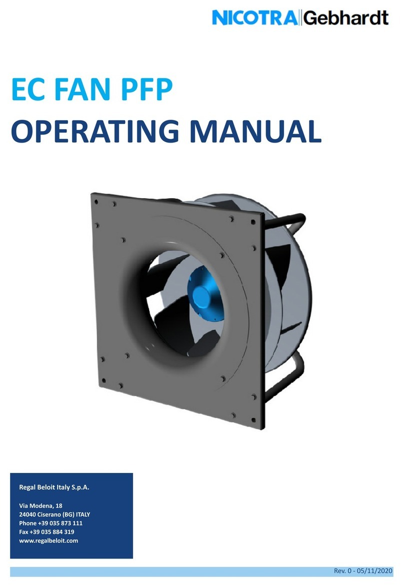
Nicotra Gebhardt
Nicotra Gebhardt PFP User manual
Nicotra Gebhardt
Nicotra Gebhardt EC FAN RDP User manual
Nicotra Gebhardt
Nicotra Gebhardt ATEX User manual
Nicotra Gebhardt
Nicotra Gebhardt RDM 56 User manual

Nicotra Gebhardt
Nicotra Gebhardt DDMP 7/7T User manual
Nicotra Gebhardt
Nicotra Gebhardt RDP User manual
Popular Fan manuals by other brands
Parrot Uncle
Parrot Uncle F6316 Installation & operating instructions

Sulion
Sulion 075815 manual
Thermador
Thermador HMCN 36 FS installation manual

LUCCI Air
LUCCI Air NEWHAVEN 216150 Installation operation & maintenance

Lifebreath
Lifebreath HRV Series Homeowner's manual
Stirling
Stirling Black DL-20-4A quick start guide
