Nicotra Gebhardt PFP User manual
Rev. 0 - 05/11/2020
EC FAN PFP
OPERATING MANUAL
Regal Beloit Italy S.p.A.
Via Modena, 18
24040 Ciserano (BG) ITALY
Phone +39 035 873 111
Fax +39 035 884 319
www.regalbeloit.com

Rev. 0 - 05/11/2020
OPERATING MANUALOPERATING MANUAL
ENEN
2/48
INDEXINDEX
1. DEFINITIONS AND WARNINGS ..............................................................................................................................................5
1.1 Object of this manual .........................................................................................................................................................5
1.2 Symbols used......................................................................................................................................................................5
............................................................................................................................................................5
...........................................................................................................................................5
..............................................................................................................................................................6
...............................................................................................................................................................7
.............................................................................................................................................................7
2. REGULATORY REFERENCES ....................................................................................................................................................8
........................................................................................................................................8
...............................................................................................................................8
3. DATA PLATE .............................................................................................................................................................................9
4. TRANSPORT AND STORAGE.................................................................................................................................................10
5. PACKING CONTENTS.............................................................................................................................................................10
6. UNPACKING ...........................................................................................................................................................................11
7. PRODUCT DESCRIPTION.......................................................................................................................................................12
8. TECHNICAL FEATURES..........................................................................................................................................................13
......................................................................................................................................................13
9. INSTALLATION .......................................................................................................................................................................14
...................................................................................................................................................................14
.........................................................................................................................................................................14
...........................................................................................................................................14
.................................................................................................................................................................14
.......................................................................................................................................................15
.........................................................................................................................................15
.......................................................................................................................................................16
..................................................................................................................................................................18
...........................................................................................................................................................19
........................................................................................................................................20
...................................................................................................................................................21
..........................................................................................................................................................21
..............................................................................................................................23
................................................................................................................................................24
..............................................................................................................................24
..................................................................................................25
..............................................................................................................................25
...........................................................................................................26
........................................................................................................................................26
10. OPERATING MODES AND SETTING OPTIONS.....................................................................................................................27

Rev. 0 - 05/11/2020
OPERATING MANUALOPERATING MANUAL
ENEN
3/48
..................................................................................................................................................................27
.............................................................................................................................................27
.........................................................................................................................27
..................................................................................................................................28
............................................................................................................................28
.............................................................................................................................................................28
................................................................................................................................................28
..................................................................................................................................................29
........................................................................................................................29
....................................................................................................29
.............................................................................................................29
......................................................................................................................30
.......................................................................................................................................30
11. VOLUMETER MEASUREMENT SYSTEM FOR VOLUME FLOW RATE ..................................................................................31
..................................................................................................................................31
...............................................................................................32
12. OTHER FEATURES..................................................................................................................................................................33
.....................................................................................................................................................................33
......................................................................................................................................33
.........................................................................................................................................33
.....................................................................................................................................33
...............................................................................................................................33
.........................................................................................................................................................................34
13. SOA LIMITATIONS .................................................................................................................................................................34
.............................................................................................................................................................34
.............................................................................................................................................................34
13.3 ...............................................................................................................................................34
13.4.....................................................................................................................35
14. OTHER VARIABLES ................................................................................................................................................................35
14.1 .....................................................................................................................................................................35
14.2 .................................................................................................................................................................35
14.3 ..............................................................................................................................................................35
15. DERATING AND OVERHEATING PROTECTIONS ..................................................................................................................35
15.1 .......................................................................................................................................35
15.2 ...................................................................................................................36
16. MASTER & SLAVE MODE ......................................................................................................................................................36
16.1 ...................................................................................................................................36
16.2 .................................................................................................................................36
17. ...........................................................................................37
18. COMMUNICATION................................................................................................................................................................37

Rev. 0 - 05/11/2020
OPERATING MANUALOPERATING MANUAL
ENEN
4/48
18.1 .............................................................................................................................................38
18.2 .....................................................................................................................................................38
18.3 ...........................................................................................................................................39
18.4 ...............................................................................................................................................44
18.5 .......................................................................................................................................45
19. ALARM HANDLING ...............................................................................................................................................................46
19.1 ......................................................................................................................................................................46
19.2 ............................................................................................................................46
19.3 ....................................................................................................................................46
19.4 .......................................................................................................................................................47
19.5 .....................................................................................................................................................................47
20. AVAILABLE SOFTWARE.........................................................................................................................................................47

Rev. 0 - 05/11/2020
OPERATING MANUALOPERATING MANUAL
ENEN
5/48
1. DEFINITIONS AND WARNINGS
1.2 Symbols used
1.3 Qualified personnel
•
•
•
1.4 Use for intended purpose only
Nicotra Gebhardt.
As to the "WARNING" and "CAUTION"-
As to the "NOTICE"
Pictogram Descripon
WARNINGWARNING
CAUTIONCAUTION
1.1 Object of this manual
This manual refers to fans having a driver with a 5 rmware revision or higher.
Rev. 0 - 05/11/2020
OPERATING MANUALOPERATING MANUAL
ENEN
6/48
This manual is an integral part of the EC Fan PFP and it must be carefully read before using it since it gives important
indicaons with regards to its safe installaon, use and maintenance. Keep it with care.
Before using the EC Fan PFP, read carefully the following general safety rules.
•
•
RISK OF ELECTRICAL SHOCKS
•
•
•
• the fan.
Any installaon and/or maintenance tasks are only to be carried out by skilled, specialist personnel.
Exisng electrical systems must comply with the rules in force in the country where the PFP fan is installed.
Before doing any maintenance, make sure that the power supply and the baeries have been disconnected.
Install an all-pole disconnecng device in the power supply system (in accordance with IEC 60335-1 or IEC 60204-1, as
applicable).
Conform to the wiring diagrams shown in the secon “ELECTRICAL CONNECTIONS” of this manual.
Please read the informaon carefully, since it is provided for your personal safety and will also help prolonging the service life
of your fan.
1.5 Safety instructions
WARNINGWARNING
This appliance can be used by children aged from 8 years and above and persons with reduced physical, sensory or mental
capabilies or lack of experience and knowledge on condion that they are supervised and instructed concerning use of the
appliance in a safe way and understand the hazards involved.
-> Children shall not play with the appliance
-> Cleaning and user maintenance shall not be made by children without supervision
WARNINGWARNING
The use and maintenance manual of any domesc appliance or similar device incorporang a PFP fan shall include the
following clauses.
WARNINGWARNING
Rev. 0 - 05/11/2020
OPERATING MANUALOPERATING MANUAL
ENEN
7/48
ALL RIGHTS ARE RESERVED ACCORDING TO THE
INTERNATIONAL COPYRIGHT CONVENTIONS,
The Nicotra Gebhardt -
1.6 Informative letter
WARNINGWARNING
The original conguraon of the fan must not be changed at all, except as prescribed in this manual.
On receiving the fan, make sure the supply corresponds to what has been ordered.
In case of non-compliance immediately inform the manufacturer.
Also make sure the PFP fan has not been damaged during transport.
For informaon concerning the nearest supporng center, please get in touch with your retailer.
WARNINGWARNING
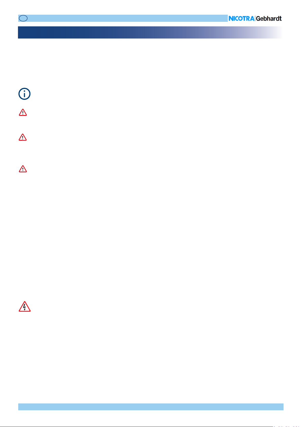
1.7 Safe operating area
Customer Care Technical Service

Rev. 0 - 05/11/2020
OPERATING MANUALOPERATING MANUAL
ENEN
8/48
2. REGULATORY REFERENCES
Machinery
Direcve (MD - Dir. 2006/42/EU)Low-Voltage Direcve (Dir. 2014/35/EU)-
EN 60204-1 standard “Electrical equipment of ma-
chines - General requirements”.
Nicotra Gebhardt
2.1 Mechanical and electrical safety
Single-phase drive systems: PFP 1.35 kW
-
EN 61000-6-3 – Electromagnec compability (EMC). Part 6-3
Three-phase drive systems: PFP 2.6 kW, 4 kW
-
EN 61000-6-4 – Electromagnec compability (EMC). Part 6-4
2.2 Electro-Magnetic Compatibility (EMC)
Specic electrical safety and EMC standards are applied according to the available models of conformity declaraon
(idened as 985732 and 985748):
EMC standards
61000-6-3
61000-6-4
Electrical
safety
standards
60204
985732 985748
To improve the Electromagnec compability a ferrite should be put on the power supply cable (close to the driver). The
compliancy to the standards is intended for a single fan. No tests have been made on mulple installaons.
Rev. 0 - 05/11/2020
OPERATING MANUALOPERATING MANUAL
ENEN
9/48
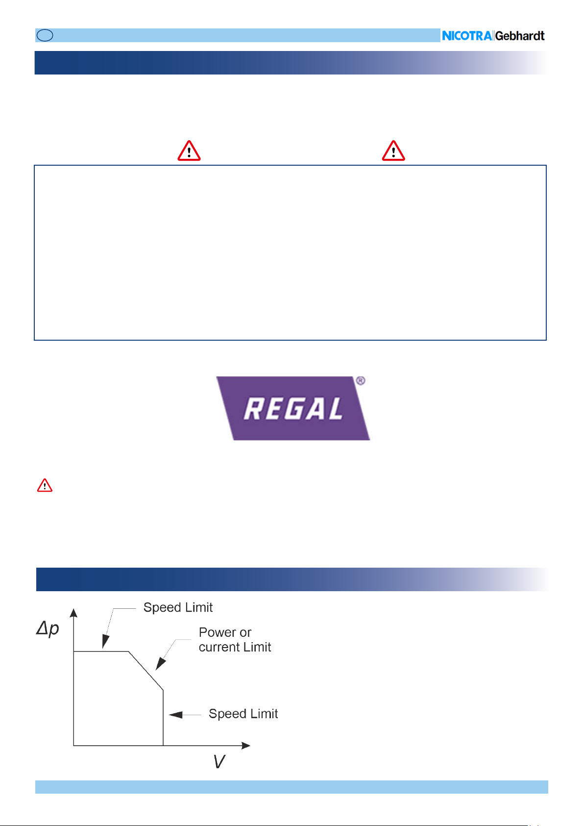
3. DATA PLATE
The company is not to be held responsible for damage to property or accidents to people which might occur if the above-men-
oned warnings are not observed. In such a case, the operator is the only person responsible.
REF. DESCRIPTION
1 MODEL DESIGNATION
2 REGAL BELOIT ITALY CODE
3 MODIFICATION LEVEL
4 PRODUCTION LOT NO.
5 NO. PHASES & CURRENT TYPE
6 ELECTRICAL FREQUENCY
7 VOLTAGE
8 IP PROTECTION GRADE
9 MOTOR INSULATION CLASS
10
11 MAXIMUM CURRENT INPUT
12 MOTOR RATED POWER
13 RATED RPM
The compliancy to the standards are intended for a single fan.
No tests have been made on mulple installaons.
The EMC tests are conducted without 485 communicaon wire, analog signals or Bluetooth devices.
WARNINGWARNING
REF. DESCRIPTION
14
15 OPERATING TEMPERATURE RANGE
16
17
18 OPERATING MANUAL
19
20
21 MEASUREMENT CATEGORY USED TO DETER-
22 EFFICIENCY GRADE AT OPTIMUM ENERGY EFFI-
CIENCY POINT
23
24
25 PRODUCTION DATE

Rev. 0 - 05/11/2020
OPERATING MANUALOPERATING MANUAL
ENEN
10/48
6xxxxxxxxxxxxxxx
pfp xxxxxx xx xxx xxxx xxx
123456
4. TRANSPORT & STORAGE
Correct transport, storage, erecon and mounng, as well as careful operaon and maintenance are essenal for proper and
safe operaon of the equipment.
Protect the fan against physical shocks and vibraon during transport and storage. Also, be sure to protect it against water
(rainfall) and excessive temperatures.
WARNINGWARNING
If the fan must be subject to long-term storage, the storage me without applicaon of any power supply shall not exceed two
years since fan producon or since operang the fan for at least half-an-hour connuously.
The storage site shall have a temperature between -20°C and +70 °C, a Relave Humidity lower than 75%, and not be subject
to condensaon or exposed to dust.
CAUTIONCAUTION
5. PACKING CONTENTS
REF. DESCRIPTION
1 ART. CODE
2 MODEL DESCRIPTION
3 BATCH CODE
1
2
3

Rev. 0 - 05/11/2020
OPERATING MANUALOPERATING MANUAL
ENEN
11/48
6. UNPACKING
Check the fan. Before installing the PFP fan, check to ensure that all of the items listed are present and that there are no visible
signs of damage.
WARNINGWARNING
Dispose of all packing components in compliance with the laws in force in the country of use.
RECYCLE
Rev. 0 - 05/11/2020
OPERATING MANUALOPERATING MANUAL
ENEN
12/48
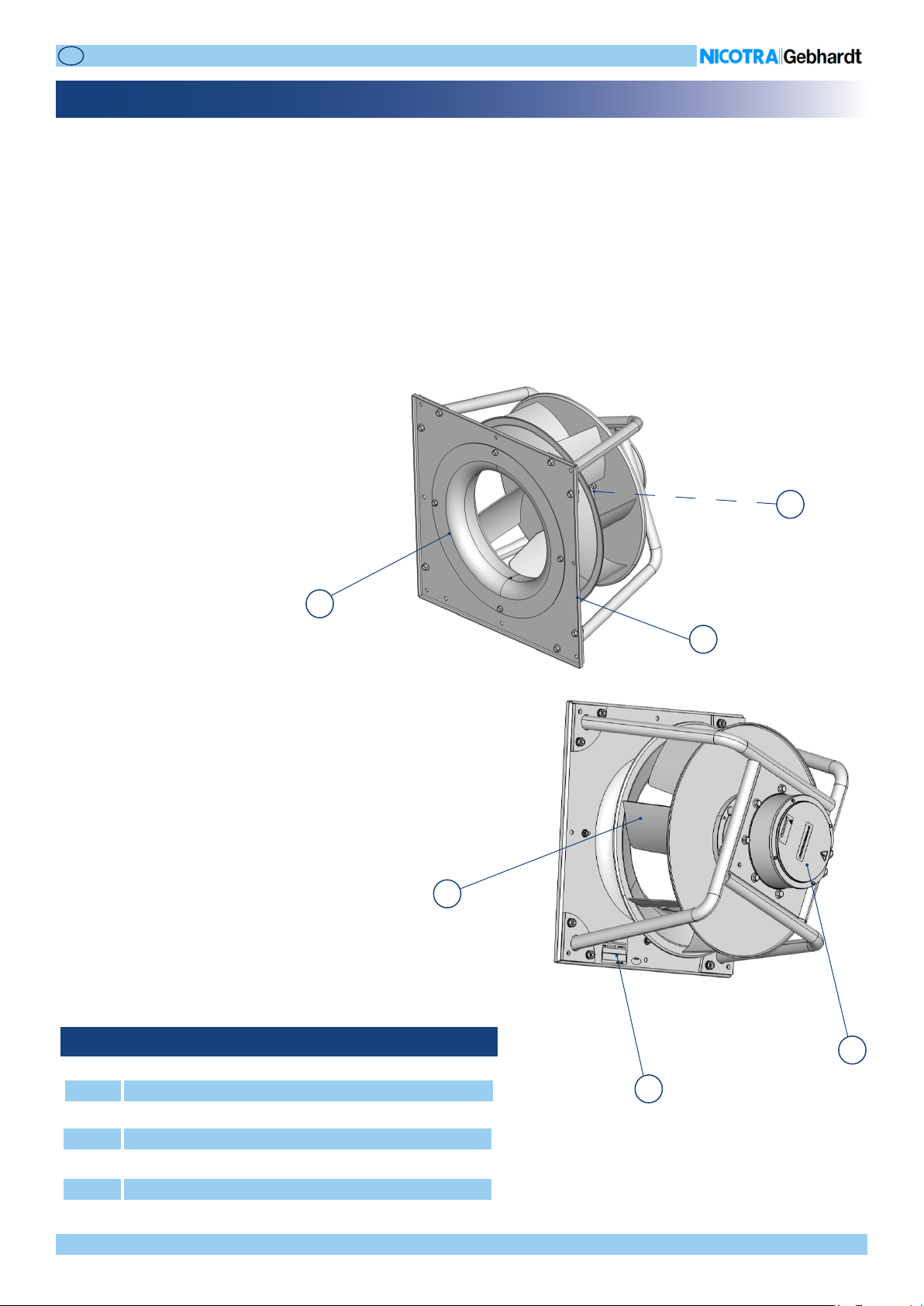
7. PRODUCT DESCRIPTION
Features
•
•
•
•
•
•
•
Performance
•
•
•
•
Protecon
•
•
•
•
•
•
REF. DESCRIPTION
1
2
3
4
5
6
1
3
2
5
4
6
Rev. 0 - 05/11/2020
OPERATING MANUALOPERATING MANUAL
ENEN
13/48
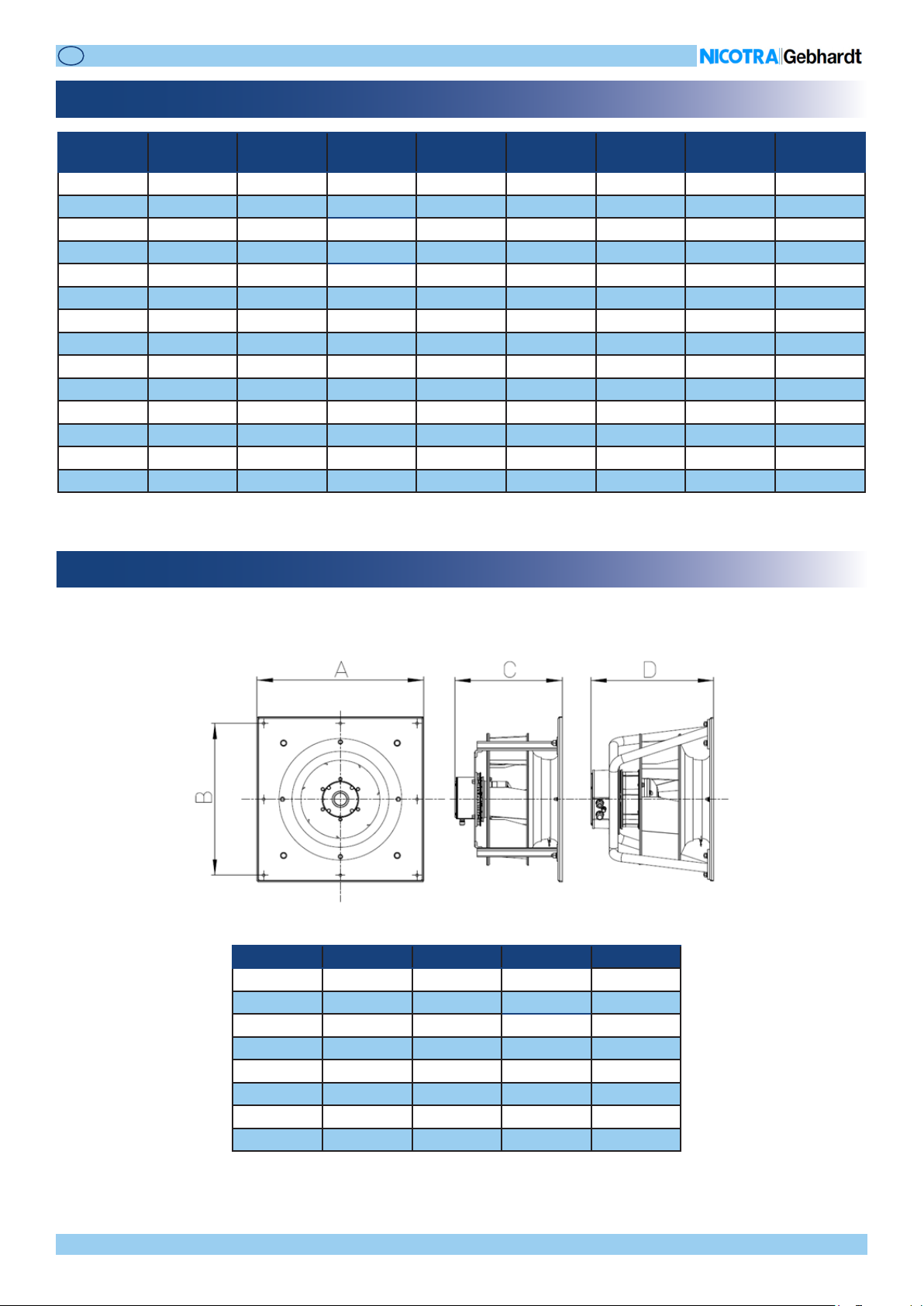
8. TECHNICAL FEATURES
8.1 Dimensional drawings
Size Motor code Driver code Driver
phases
Abs. curr.
(A)
Abs. pow.
(W)
Min. temp.
(°C)
Max. temp.
(°C)
IP class
protecon
280 1416F0 1431F2 1 Ph 5.72 1363 -20°C +40°C IP 54
280 1416F8 1431F3 3 Ph 2.07 1320 -20°C +40°C IP 54
315 1416F0 1431F2 1 Ph 5.82 1365 -20°C +40°C IP 54
315 1416F8 1431F3 3 Ph 2.34 1500 -20°C +40°C IP 54
355 1416F1 1431F2 1 Ph 5.74 1378 -20°C +40°C IP 54
355 1416F6 1431F3 3 Ph 3.24 2110 -20°C +40°C IP 54
400 1416F1 1431F2 1 Ph 5.74 1347 -20°C +40°C IP 54
400 1416F5 1431F3 3 Ph 4 2600 -20°C +40°C IP 54
450 1416F1 1431F2 1 Ph 5.71 1327 -20°C +40°C IP 54
450 1416F7 1431F3 3 Ph 3.64 2370 -20°C +40°C IP 54
450 1416G2 1431F9 3 Ph 4.5 2860 -20°C +40°C IP 54
500 1416F2 1431F2 1 Ph 5.82 1390 -20°C +40°C IP 54
500 1416G1 1431F9 3 Ph 5.96 4122 -20°C +40°C IP 54
560 1416G0 1431F9 3 Ph 5.86 3980 -20°C +40°C IP 54
ABCand D
Size A B C D
280 400 350 309 -
315 500 450 329 -
355 500 450 354 -
400 500 450 379 -
450 630 580 406 469
500 630 580 440 503
560 800 750 - 539
630 800 750 - 573
Rev. 0 - 05/11/2020
OPERATING MANUALOPERATING MANUAL
ENEN
14/48
9. INSTALLATION
The fan installaon must be carried out only by competent and qualied sta.
9.1 Commisioning
Work on the device/system by unqualied personnel or failure to comply with warnings can result in severe personal injury or
serious damage to material.
Only suitably qualied personnel trained in the setup, installaon, commissioning and operaon of the product should carry
out work on the device/system.
The PFP fan must be grounded through the PE connector on the driver.
The following terminals can carry dangerous voltages even if the driver is inoperave:
• the power supply terminals L, N or R, S, T
• the motor terminals U, V, W
WARNINGWARNING
In the nal installaon, the device shall be directly connected to the supply terminals and shall have a contact separaon in all
poles, providing full disconnecon under overvoltage category III condions.
WARNINGWARNING
9.2 Operation
The driver must NOT be removed from the related PFP fan type and size.
The driver cannot be used separate from the related fan.
WARNINGWARNING
Ensure correct grounding connecons. The ground cable must be enough to carry the maximum supply fault current which nor-
mally will be limited by the fuses or MCB. Suitably rated fuses or MCB should be ed in the main supply to the driver, according
to any local legislaon or codes.
WARNINGWARNING
The driver operates at high voltages.
Certain parameter sengs may cause the driver to restart automacally aer an input power failure.
CAUTIONCAUTION
9.3 Ambient operating conditions
The installaon place must be in accordance with the IP protecon degree of the fan. In this respect, refer to the ID plate de-
scribed in chapter 3.
Humidity Range: 90% non-condensing
Altude: if the fan is to be installed at an altude > 1000m, derang is required.
Shocks: do not drop the fan or expose it to sudden shock.
Vibraon: do not install the fan in an area where it is likely to be exposed to constant vibraons.
CAUTIONCAUTION
9.4 Fan installation

Rev. 0 - 05/11/2020
OPERATING MANUALOPERATING MANUAL
ENEN
15/48
9.5 Accessory installation
9.5.1 Inlet protection guard kit
Materials
Assembly
•
•
Sizes 280 - 630
Sizes 315 - 355 - 400 - 450 - 500 - 560
Size Code A B C
280 R7220A 298.4 284 214
315 R7221A 342.4 317 274
355 R7222A 377.4 352 314
400 R7223A 417.4 392 354
450 R7224A 463.4 438 394
500 R7225A 513.4 488 434
560 R7226A 563.4 538 434
630 R7227A 615.4 601 494
1
2
3
Rev. 0 - 05/11/2020
OPERATING MANUALOPERATING MANUAL
ENEN
16/48
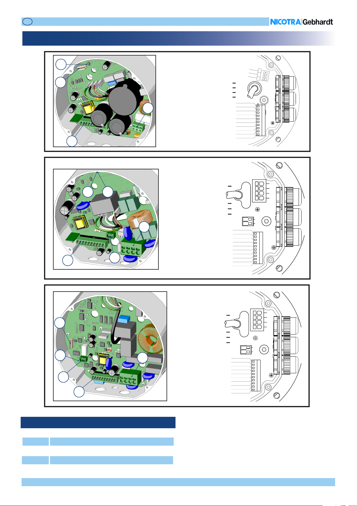
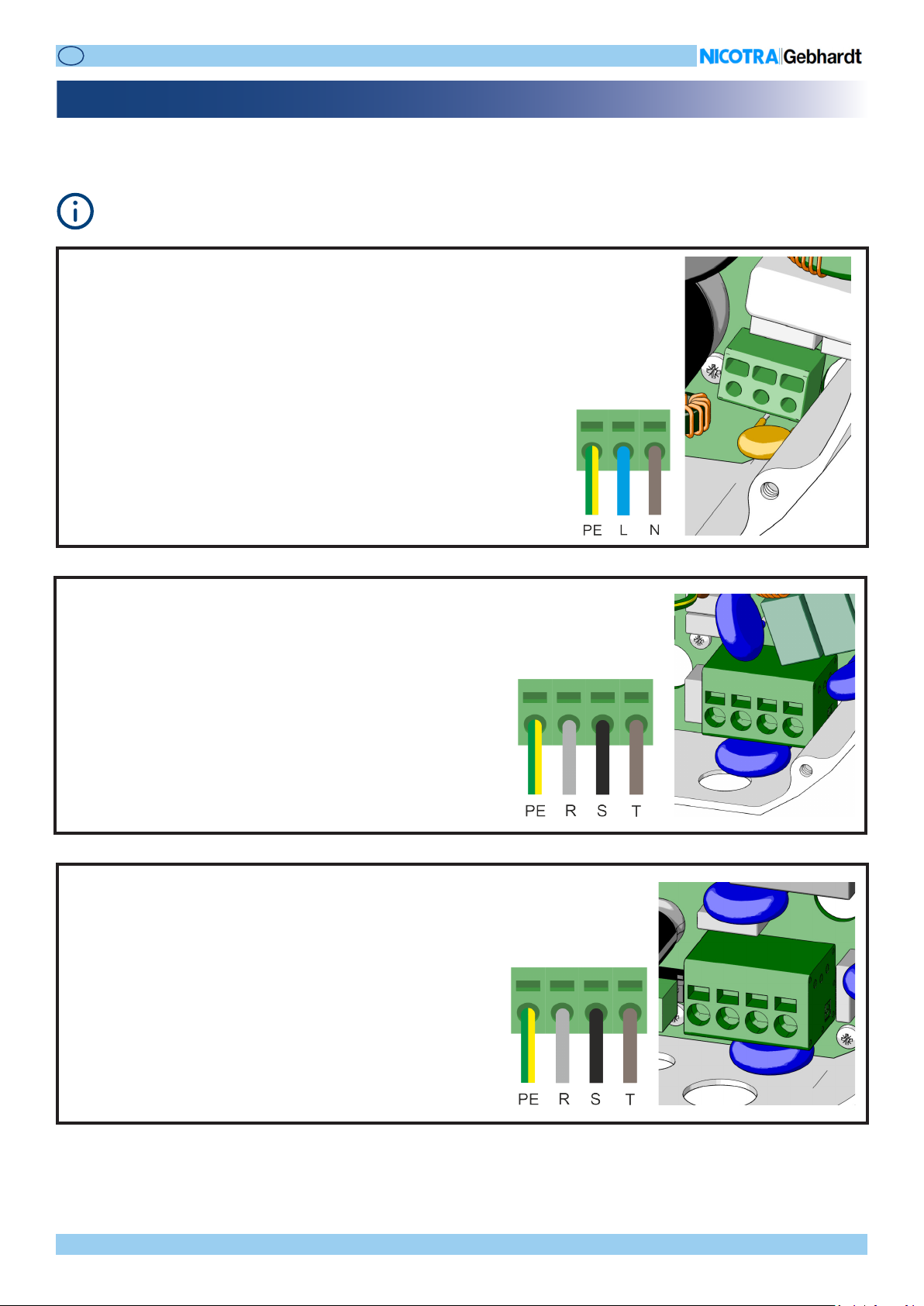
9.6 Electrical connections
PFP 1.35kW 1-Phase
PFP 2.6kW 3-Phase
PFP 4kW 3-Phase
REF. DESCRIPTION
1
2
3
4
5
PE Y/GREEN
W BLACK
V BROWN
U GREY
NOC
TSPE R
TACHO/ALARM/FILTER
GND
MODBUS - B
MODBUS - A
GND
TRANSDUCER INPUT
ANALOG INPUT
ENABLE
+10V
+24V
U GREY
V BROWN
W BLACK
PE Y/GREEN
CN O
RPE ST
ANALOG INPUT
ENABLE
+10V
+24V
TRANSDUCER INPUT
GND
MODBUS - A
MODBUS - B
GND
TACHO/ALARM/FILTER
PE
L
N
ANALOG INPUT
ENABLE
+10V
+24V
TRANSDUCER INPUT
GND
MODBUS - A
MODBUS - B
GND
TACHO/ALARM/FILTER
U GREY
W BLACK
PE Y/GREEN
V BROWN
1
2
3
1
2
1
2
5
5
4
3
4
3 4

Rev. 0 - 05/11/2020
OPERATING MANUALOPERATING MANUAL
ENEN
17/48
Make sure that a dierenal switch (circuit breaker) has been installed upstream the line and that it funcons properly.
Before carrying out any intervenon on the electrical system, disconnect the power supply by means of main switch.
Work on the driver/fan by unqualied personnel or failure to comply with warnings can result in severe personal injury or serious
damage to material.
Only suitably qualied personnel trained in the set-up, installaon, commissioning and operaon of the product should carry
out work on the driver/fan. This driver must be grounded.
The power supply terminals L, N (1-Phase) or R, S, T (3-Phase) and the motor terminals U, V, W can carry dangerous voltages
even if the driver is inoperave.
WARNINGWARNING

Rev. 0 - 05/11/2020
OPERATING MANUALOPERATING MANUAL
ENEN
18/48
Tacho/Alrm/Filter
GND
Modbus - B
Modbus - A
GND
Analog Input
Enable
+10V
No
C
PE
R
S
T
+24V
Transducer input
6
8
4
1
7
2
5
4
3
2
1
Grey
Brown
Blue
White
Yellow
Red
Pink
Yellow / Green
Black 3
Black 2
Black 1
Connector
code 144144
Connector
code 144143
9.6.1 Optionals
• Phoenix Contact SACC-E-M12FS-8CON-PG9/0,5 (1) Phoenix Contact SACC-E-M12MSS-3P-M16/0,5 PE
(2)
• Phoenix Contact SACC-E-M12FS-8CON-PG9/0,5 (1) Phoenix Contact SACC-E-M12MSS-4CON-M16/0,5 PE
(2).
1
2
Tacho/Alrm/Filter
GND
Modbus - B
Modbus - A
GND
Analog Input
Enable
+10V
No
C
PE
R
S
T
+24V
Transducer input
6
8
4
1
7
2
5
4
3
2
1
Grey
Brown
Blue
White
Yellow
Red
Pink
Yellow / Green
Black 3
Black 2
Black 1
Connector
code 144144
Connector
code 144143
Tacho/Alrm/Filter
GND
Modbus - B
Modbus - A
GND
Analog Input
Enable
+10V
No
C
PE
R
S
T
+24V
Transducer input
6
8
4
1
7
2
5
4
3
2
1
Grey
Brown
Blue
White
Yellow
Red
Pink
Yellow / Green
Black 3
Black 2
Black 1
Connector
code 144144
Connector
code 144143
Tacho/Alrm/Filter
GND
Modbus - B
Modbus - A
GND
Analog Input
Enable
+10V
No
C
PE
R
S
T
+24V
Transducer input
6
8
4
1
7
2
5
4
3
2
1
Grey
Brown
Blue
White
Yellow
Red
Pink
Yellow / Green
Black 3
Black 2
Black 1
Connector
code 144144
Connector
code 144143
Tacho/Alrm/Filter
GND
Modbus - B
Modbus - A
GND
Analog Input
Enable
+10V
No
C
PE
R
S
T
+24V
Transducer input
6
8
4
1
7
2
5
4
3
2
1
Grey
Brown
Blue
White
Yellow
Red
Pink
Yellow / Green
Black 3
Black 2
Black 1
Connector
code 144144
Connector
code 144143
Tacho/Alrm/Filter
GND
Modbus - B
Modbus - A
GND
Analog Input
Enable
+10V
No
C
PE
R
S
T
+24V
Transducer input
6
8
4
1
7
2
5
4
3
2
1
Grey
Brown
Blue
White
Yellow
Red
Pink
Yellow / Green
Black 3
Black 2
Black 1
Connector
code 144144
Connector
code 144143
Tacho/Alrm/Filter
GND
Modbus - B
Modbus - A
GND
Analog Input
Enable
+10V
No
C
PE
R
S
T
+24V
Transducer input
6
8
4
1
7
2
5
4
3
2
1
Grey
Brown
Blue
White
Yellow
Red
Pink
Yellow / Green
Black 3
Black 2
Black 1
Connector
code 144144
Connector
code 144143
Tacho/Alrm/Filter
GND
Modbus - B
Modbus - A
GND
Analog Input
Enable
+10V
No
C
PE
R
S
T
+24V
Transducer input
6
8
4
1
7
2
5
4
3
2
1
Grey
Brown
Blue
White
Yellow
Red
Pink
Yellow / Green
Black 3
Black 2
Black 1
Connector
code 144144
Connector
code 144143
Tacho/Alrm/Filter
GND
Modbus - B
Modbus - A
GND
Analog Input
Enable
+10V
No
C
PE
R
S
T
+24V
Transducer input
6
8
4
1
7
2
5
4
3
2
1
Grey
Brown
Blue
White
Yellow
Red
Pink
Yellow / Green
Black 3
Black 2
Black 1
Connector
code 144144
Connector
code 144143
Rev. 0 - 05/11/2020
OPERATING MANUALOPERATING MANUAL
ENEN
19/48
PFP 4kW 3-Phase
-
Min. and max. wire secon:
•
9.6.2 Power supply
Nicotra Gebhardt.
PFP 1.35kW 1-Phase
Min. and max. wire secon:
•
PFP 2.65kW 3-Phase
-
Min. and max. wire secon:
•
As concerns the cable minimum secon, check the requirements issued by the country of installaon.
Rev. 0 - 05/11/2020
OPERATING MANUALOPERATING MANUAL
ENEN
20/48
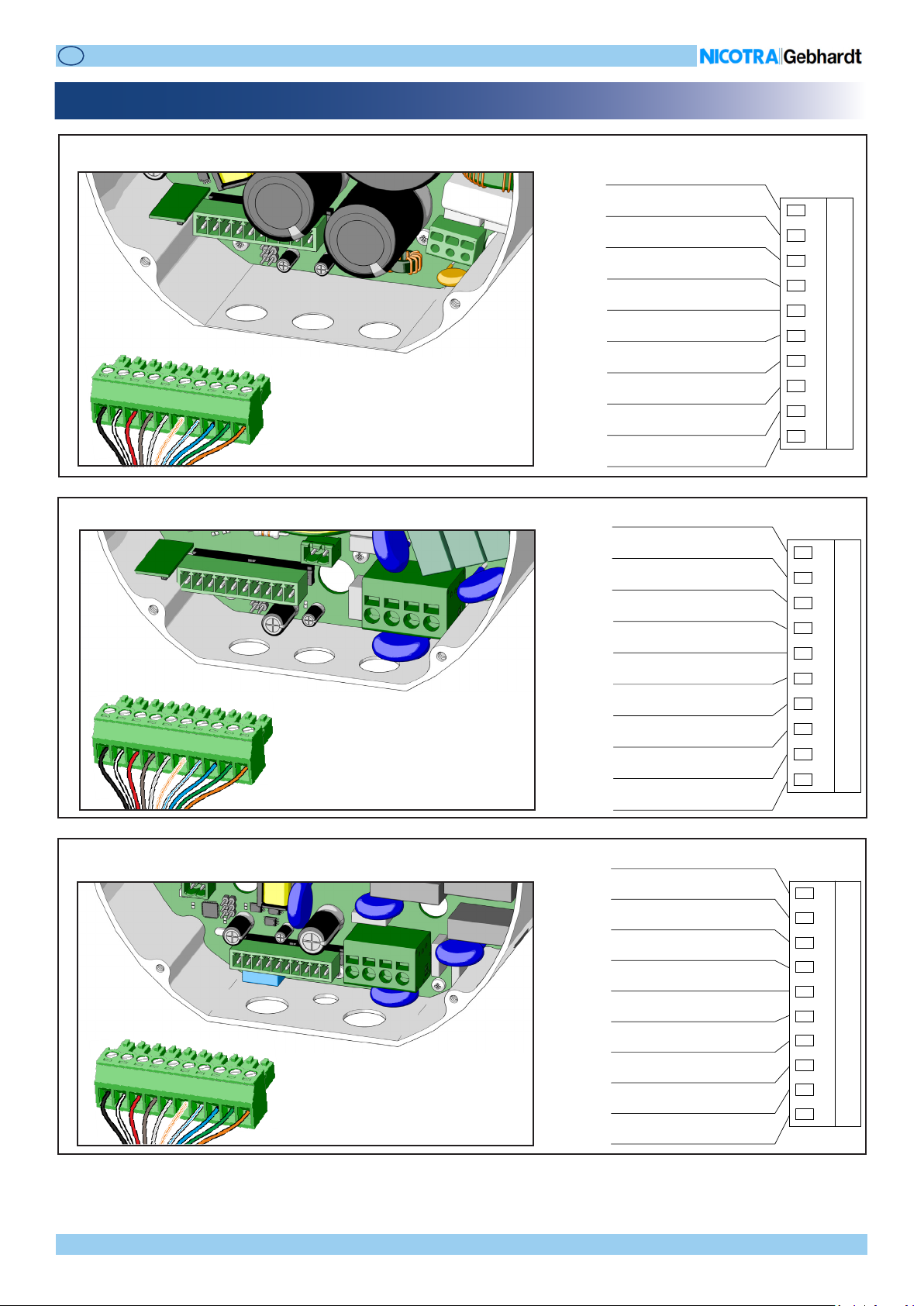
9.6.3 Control board connection
PFP 1.35kW 1-Phase
PFP 2.65kW 3-Phase
PFP 4kW 3-Phase
4 ANALOG INPUT
3 ENABLE
2 +10V
1 +24V
5 TRANSDUCER INPUT
6 GND
7 MODBUS - A
8 MODBUS - B
9 GND
10 TACHO/ALARM/FILTER
4 ANALOG INPUT
3 ENABLE
2 +10V
1 +24V
5 TRANSDUCER INPUT
6 GND
7 MODBUS - A
8 MODBUS - B
9 GND
10 TACHO/ALARM/FILTER
10 ← 1
10 ← 1
10 ← 1
Min. and max. secon:
• 0.13 - 1.31 mm2
1 TACHO/ALARM/FILTER
2 GND
3 MODBUS - B
4 MODBUS - A
5 GND
6 TRANSDUCER INPUT
7 ANALOG INPUT
8 ENABLE
9 +10V
10 +24V
Table of contents
Other Nicotra Gebhardt Fan manuals

Nicotra Gebhardt
Nicotra Gebhardt RDM 56 User manual

Nicotra Gebhardt
Nicotra Gebhardt ATEX User manual

Nicotra Gebhardt
Nicotra Gebhardt DDMP 7/7T User manual

Nicotra Gebhardt
Nicotra Gebhardt AT Series Manual

Nicotra Gebhardt
Nicotra Gebhardt EC FAN RDP User manual

Nicotra Gebhardt
Nicotra Gebhardt RDP User manual
Popular Fan manuals by other brands


SpeedComfort
SpeedComfort Trio Set manual

UNITED
UNITED UCF-699 instruction manual

Westinghouse
Westinghouse Contempra Trio owner's manual

Soleus Air
Soleus Air FF1-50-53 owner's manual

Maico
Maico ECA 150 ipro VZC Mounting and operating instructions

KDK
KDK X48XG / X48XGMN Operating and installation instructions