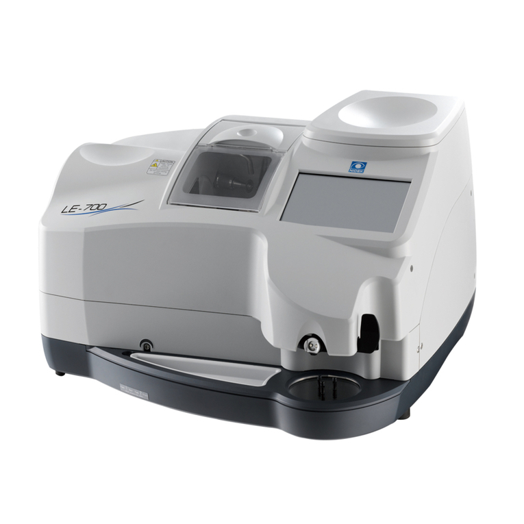
Nidek Medical LE-700 User manual

OPERATOR’S MANUAL
OPERATOR’S MANUAL
Edging Station

April 2013
45301-P902-A
Printed in Japan
NIDEK CO., LTD. : 34-14, Maehama, Hiroishi-cho, Gamagori, Aichi 443-0038, Japan
(Manufacturer) Telephone: +81-533-67-6611
Facsimile: +81-533-67-6610
NIDEK CO., LTD. : 3F Sumitomo Fudosan Hongo Bldg., 3-22-5, Hongo,
(Tokyo Office) Bunkyo-Ku, Tokyo 113-0033, Japan
Telephone: +81-3-5844-2641
Facsimile: +81-3-5844-2642
NIDEK INCORPORATED : 47651 Westinghouse Drive, Fremont, California 94539, U. S. A.
(United States Agent) Telephone: +1-510-226-5700
Facsimile: +1-510-226-5750
NIDEK S.A. : Europarc 13, rue Auguste Perret, 94042 Créteil, France
(EU Authorized Representative) Telephone: +33-1-49 80 97 97
Facsimile: +33-1-49 80 32 08
Original instructions
2013 NIDEK CO., LTD.
C

Before Use
I
45301-P902-A
This OPERATOR’S MANUAL contains information necessary for
the operation of the NIDEK Edging Station LE-700.
This manual includes operating procedures, safety precautions,
specifications, and information about accessories and mainte-
nance. This manual is necessary for proper use. Especially, the
safety precautions and operating procedures must be thoroughly
understood prior to the operation of the instrument.
Keep this manual handy for reference.
If you encounter any problems or have questions about the instru-
ment, please contact NIDEK or your authorized distributor.

II
Table of Contents
1. FOR SAFE USE . . . . . . . . . . . . . . . . . . . . . . . . . . . . . . . . . . . . . . . 1
1.1 Read before Use
- - - - - - - - - - - - - - - - - - - - - - - - - - - - - - - - - - - - - - - - - - - - - - - -1
1.2 Signal Words for Safety
- - - - - - - - - - - - - - - - - - - - - - - - - - - - - - - - - - - - - - - - - - -1
1.3 Usage Precautions
- - - - - - - - - - - - - - - - - - - - - - - - - - - - - - - - - - - - - - - - - - - - - -2
1.4 Labels and Symbols
- - - - - - - - - - - - - - - - - - - - - - - - - - - - - - - - - - - - - - - - - - - - -8
2. INTRODUCTION . . . . . . . . . . . . . . . . . . . . . . . . . . . . . . . . . . . . . .11
2.1 Outline of the Instrument
- - - - - - - - - - - - - - - - - - - - - - - - - - - - - - - - - - - - - - - - -12
2.2 Instrument Configuration
- - - - - - - - - - - - - - - - - - - - - - - - - - - - - - - - - - - - - - - - -13
2.3 Display Description
- - - - - - - - - - - - - - - - - - - - - - - - - - - - - - - - - - - - - - - - - - - - -16
2.3.1 Buttons and indications common to each screen
- - - - - - - - - - - - - - - - - - - - - -17
2.3.2 Home screen
- - - - - - - - - - - - - - - - - - - - - - - - - - - - - - - - - - - - - - - - - - - - - -20
2.3.3 Pattern tracing screen
- - - - - - - - - - - - - - - - - - - - - - - - - - - - - - - - - - - - - - - -22
2.3.4 Demo lens blocking screen
- - - - - - - - - - - - - - - - - - - - - - - - - - - - - - - - - - - - -23
2.3.5 Demo lens tracing screen
- - - - - - - - - - - - - - - - - - - - - - - - - - - - - - - - - - - - - -24
2.3.6 Frame data confirmation screen
- - - - - - - - - - - - - - - - - - - - - - - - - - - - - - - - -25
2.3.7 Processing conditions screen
- - - - - - - - - - - - - - - - - - - - - - - - - - - - - - - - - - -26
2.3.8 Layout screen
- - - - - - - - - - - - - - - - - - - - - - - - - - - - - - - - - - - - - - - - - - - - - -28
2.3.9 Keyboard screen
- - - - - - - - - - - - - - - - - - - - - - - - - - - - - - - - - - - - - - - - - - - -29
2.3.10 Shape editor screen
- - - - - - - - - - - - - - - - - - - - - - - - - - - - - - - - - - - - - - - - - -31
2.3.11 Blocking screen
- - - - - - - - - - - - - - - - - - - - - - - - - - - - - - - - - - - - - - - - - - - -32
2.3.12 Processing start screen
- - - - - - - - - - - - - - - - - - - - - - - - - - - - - - - - - - - - - - -35
2.3.13 Simulation screen
- - - - - - - - - - - - - - - - - - - - - - - - - - - - - - - - - - - - - - - - - - -36
2.3.14 Retouch panel
- - - - - - - - - - - - - - - - - - - - - - - - - - - - - - - - - - - - - - - - - - - - -38
2.3.15 Processing conditions confirmation panel
- - - - - - - - - - - - - - - - - - - - - - - - - - -39
2.4 Packed Contents
- - - - - - - - - - - - - - - - - - - - - - - - - - - - - - - - - - - - - - - - - - - - - - -40
2.5 Connection Configuration
- - - - - - - - - - - - - - - - - - - - - - - - - - - - - - - - - - - - - - - -41
2.5.1 LT-980 connection and communication setting
- - - - - - - - - - - - - - - - - - - - - - - -41
2.5.2 NIDEK LAN connection
- - - - - - - - - - - - - - - - - - - - - - - - - - - - - - - - - - - - - - -43
2.5.3 VCA connection
- - - - - - - - - - - - - - - - - - - - - - - - - - - - - - - - - - - - - - - - - - - -46
3. OPERATING PROCEDURE . . . . . . . . . . . . . . . . . . . . . . . . . . . . 49
3.1 Operation Flow
- - - - - - - - - - - - - - - - - - - - - - - - - - - - - - - - - - - - - - - - - - - - - - - -51
3.2 Startup and Shutdown
- - - - - - - - - - - - - - - - - - - - - - - - - - - - - - - - - - - - - - - - - - -52
3.2.1 Check before use
- - - - - - - - - - - - - - - - - - - - - - - - - - - - - - - - - - - - - - - - - - -52
3.2.2 Startup
- - - - - - - - - - - - - - - - - - - - - - - - - - - - - - - - - - - - - - - - - - - - - - - - - -53
3.2.3 Shutdown
- - - - - - - - - - - - - - - - - - - - - - - - - - - - - - - - - - - - - - - - - - - - - - - -54
3.2.4 Check after use
- - - - - - - - - - - - - - - - - - - - - - - - - - - - - - - - - - - - - - - - - - - - -54
3.3 Pattern or Demo Lens Tracing
- - - - - - - - - - - - - - - - - - - - - - - - - - - - - - - - - - - -55

III
:
3.3.1 Pattern tracing
- - - - - - - - - - - - - - - - - - - - - - - - - - - - - - - - - - - - - - - - - - - - - 55
3.3.2 Demo lens tracing
- - - - - - - - - - - - - - - - - - - - - - - - - - - - - - - - - - - - - - - - - - 57
3.4 Loading Shape Data
- - - - - - - - - - - - - - - - - - - - - - - - - - - - - - - - - - - - - - - - - - - 59
3.4.1 Loading data from the internal memory
- - - - - - - - - - - - - - - - - - - - - - - - - - - - 59
3.4.2 Loading data from the server
- - - - - - - - - - - - - - - - - - - - - - - - - - - - - - - - - - - 60
3.4.3 Loading data from a tracer
- - - - - - - - - - - - - - - - - - - - - - - - - - - - - - - - - - - - - 61
3.5 Saving or Deleting Shape Data
- - - - - - - - - - - - - - - - - - - - - - - - - - - - - - - - - - - 62
3.5.1 Saving shape data in the internal memory
- - - - - - - - - - - - - - - - - - - - - - - - - - 62
3.5.2 Sending shape data to the server
- - - - - - - - - - - - - - - - - - - - - - - - - - - - - - - - 64
3.5.3 Deleting data
- - - - - - - - - - - - - - - - - - - - - - - - - - - - - - - - - - - - - - - - - - - - - - 65
3.5.4 Backing up shape data to the optional USB flash drive
- - - - - - - - - - - - - - - - - - 67
3.5.5 Restoring shape data from the optional USB flash drive
- - - - - - - - - - - - - - - - - 68
3.6 Frame Data Confirmation Screen Entry
- - - - - - - - - - - - - - - - - - - - - - - - - - - - - 71
3.7 Processing Conditions Entry
- - - - - - - - - - - - - - - - - - - - - - - - - - - - - - - - - - - - - 72
3.8 Layout Entry
- - - - - - - - - - - - - - - - - - - - - - - - - - - - - - - - - - - - - - - - - - - - - - - - - - 75
3.8.1 Entering layout data for single vision lenses
- - - - - - - - - - - - - - - - - - - - - - - - - 75
3.8.2 Entering layout data for bifocal lenses
- - - - - - - - - - - - - - - - - - - - - - - - - - - - - 79
3.8.3 Entering layout data for progressive power lenses
- - - - - - - - - - - - - - - - - - - - - 81
3.8.4 Entering layout data for Ex lenses
- - - - - - - - - - - - - - - - - - - - - - - - - - - - - - - - 82
3.9 Shape Change
- - - - - - - - - - - - - - - - - - - - - - - - - - - - - - - - - - - - - - - - - - - - - - - - 84
3.10 WD or EP Entry
- - - - - - - - - - - - - - - - - - - - - - - - - - - - - - - - - - - - - - - - - - - - - - - 85
3.11 Initial Screen Customize Function
- - - - - - - - - - - - - - - - - - - - - - - - - - - - - - - - - 87
3.12 Lens Blocking
- - - - - - - - - - - - - - - - - - - - - - - - - - - - - - - - - - - - - - - - - - - - - - - - - 89
3.13 Beveling
- - - - - - - - - - - - - - - - - - - - - - - - - - - - - - - - - - - - - - - - - - - - - - - - - - - - - 95
3.13.1 Auto beveling
- - - - - - - - - - - - - - - - - - - - - - - - - - - - - - - - - - - - - - - - - - - - - 95
3.13.2 Guided beveling
- - - - - - - - - - - - - - - - - - - - - - - - - - - - - - - - - - - - - - - - - - - - 98
3.13.3 Ex lens processing (beveling)
- - - - - - - - - - - - - - - - - - - - - - - - - - - - - - - - - - 104
3.14 Flat Edging
- - - - - - - - - - - - - - - - - - - - - - - - - - - - - - - - - - - - - - - - - - - - - - - - - - 106
3.15 Grooving
- - - - - - - - - - - - - - - - - - - - - - - - - - - - - - - - - - - - - - - - - - - - - - - - - - - 108
3.15.1 Auto grooving mode
- - - - - - - - - - - - - - - - - - - - - - - - - - - - - - - - - - - - - - - - 108
3.15.2 Guided grooving mode
- - - - - - - - - - - - - - - - - - - - - - - - - - - - - - - - - - - - - - 110
3.15.3 Ex lens processing (grooving)
- - - - - - - - - - - - - - - - - - - - - - - - - - - - - - - - - 116
3.16 Size Check and Retouching
- - - - - - - - - - - - - - - - - - - - - - - - - - - - - - - - - - - - - 118
3.16.1 Size check
- - - - - - - - - - - - - - - - - - - - - - - - - - - - - - - - - - - - - - - - - - - - - - 118
3.16.2 Retouching
- - - - - - - - - - - - - - - - - - - - - - - - - - - - - - - - - - - - - - - - - - - - - - 119
3.17 Opposite Lens Processing
- - - - - - - - - - - - - - - - - - - - - - - - - - - - - - - - - - - - - - 121
3.18 Other Processing
- - - - - - - - - - - - - - - - - - - - - - - - - - - - - - - - - - - - - - - - - - - - - 122
3.18.1 Frame changing
- - - - - - - - - - - - - - - - - - - - - - - - - - - - - - - - - - - - - - - - - - - 122
3.18.2 Tilting
- - - - - - - - - - - - - - - - - - - - - - - - - - - - - - - - - - - - - - - - - - - - - - - - - - 123
3.19 Editing the Next Shape during Processing
- - - - - - - - - - - - - - - - - - - - - - - - - - 126
3.20 Removing the Lens Cup
- - - - - - - - - - - - - - - - - - - - - - - - - - - - - - - - - - - - - - - - 128
IV
:
3.20.1 Removing the half-eye lens cup
- - - - - - - - - - - - - - - - - - - - - - - - - - - - - - - - 128
3.20.2 Removing the optional pliable cup
- - - - - - - - - - - - - - - - - - - - - - - - - - - - - - - 129
3.20.3 Removing the optional mini cup
- - - - - - - - - - - - - - - - - - - - - - - - - - - - - - - - 130
3.21 After Use
- - - - - - - - - - - - - - - - - - - - - - - - - - - - - - - - - - - - - - - - - - - - - - - - - - - 131
4. SETTING AND ADJUSTMENT . . . . . . . . . . . . . . . . . . . . . . . . . 133
4.1 Menu Screen Operation
- - - - - - - - - - - - - - - - - - - - - - - - - - - - - - - - - - - - - - - - 133
4.2 General Settings
- - - - - - - - - - - - - - - - - - - - - - - - - - - - - - - - - - - - - - - - - - - - - 134
4.3 Maintenance Settings
- - - - - - - - - - - - - - - - - - - - - - - - - - - - - - - - - - - - - - - - - - 137
4.4 Grinding Settings
- - - - - - - - - - - - - - - - - - - - - - - - - - - - - - - - - - - - - - - - - - - - - 138
4.5 Connection Settings
- - - - - - - - - - - - - - - - - - - - - - - - - - - - - - - - - - - - - - - - - - - 140
4.6 Counter Display
- - - - - - - - - - - - - - - - - - - - - - - - - - - - - - - - - - - - - - - - - - - - - - 142
4.7 Calibration
- - - - - - - - - - - - - - - - - - - - - - - - - - - - - - - - - - - - - - - - - - - - - - - - - - 143
4.8 Date and Time Setting
- - - - - - - - - - - - - - - - - - - - - - - - - - - - - - - - - - - - - - - - - 146
4.9 Size Adjustment
- - - - - - - - - - - - - - - - - - - - - - - - - - - - - - - - - - - - - - - - - - - - - - 147
4.10 Axis Adjustment
- - - - - - - - - - - - - - - - - - - - - - - - - - - - - - - - - - - - - - - - - - - - - - 149
4.11 Bevel Position Adjustment
- - - - - - - - - - - - - - - - - - - - - - - - - - - - - - - - - - - - - - 151
4.12 Groove Position Adjustment
- - - - - - - - - - - - - - - - - - - - - - - - - - - - - - - - - - - - - 153
5. MAINTENANCE . . . . . . . . . . . . . . . . . . . . . . . . . . . . . . . . . . . . . 155
5.1 Troubleshooting
- - - - - - - - - - - - - - - - - - - - - - - - - - - - - - - - - - - - - - - - - - - - - - 155
5.2 Safety Features
- - - - - - - - - - - - - - - - - - - - - - - - - - - - - - - - - - - - - - - - - - - - - - 156
5.3 Periodic Check
- - - - - - - - - - - - - - - - - - - - - - - - - - - - - - - - - - - - - - - - - - - - - - - 158
5.4 Fuse Replacement
- - - - - - - - - - - - - - - - - - - - - - - - - - - - - - - - - - - - - - - - - - - - 159
5.5 Cup Holder Adjustment
- - - - - - - - - - - - - - - - - - - - - - - - - - - - - - - - - - - - - - - - 160
5.6 Wheel Dressing
- - - - - - - - - - - - - - - - - - - - - - - - - - - - - - - - - - - - - - - - - - - - - - 161
5.7 Processing Water and Filter Replacement
- - - - - - - - - - - - - - - - - - - - - - - - - - 166
5.8 Cleaning
- - - - - - - - - - - - - - - - - - - - - - - - - - - - - - - - - - - - - - - - - - - - - - - - - - - - 168
5.8.1 Cleaning the cover, display, or lens table
- - - - - - - - - - - - - - - - - - - - - - - - - - 168
5.8.2 Cleaning the cooling fan filter
- - - - - - - - - - - - - - - - - - - - - - - - - - - - - - - - - - 168
5.9 List of Consumables and Maintenance Parts
- - - - - - - - - - - - - - - - - - - - - - - - 169
6. SPECIFICATIONS . . . . . . . . . . . . . . . . . . . . . . . . . . . . . . . . . . . 171
6.1 Specifications
- - - - - - - - - - - - - - - - - - - - - - - - - - - - - - - - - - - - - - - - - - - - - - - - 171
7. INDEX . . . . . . . . . . . . . . . . . . . . . . . . . . . . . . . . . . . . . . . . . . . . . 175

1
1
FOR SAFE USE
1.1 Read before Use
1.2 Signal Words for Safety
BEFORE USE, READ THIS MANUAL.
The cautions for safety and operating procedures must be thoroughly understood before
using the instrument.
Keep this manual handy for reference.
In this manual, signal words are used to designate the degree or level of safety alert-
ing. The definitions are as follows.
WARNING
Indicates a potentially hazardous situation which, if not avoided, might result in death or seri-
ous injury.
CAUTION
Indicates a potentially hazardous situation which, if not avoided, might result in minor or
moderate injury or property damage accident.
Even situations that are labeled CAUTION might result in serious injury under certain
conditions.
Safety precautions must be strictly followed at all times.

2
FOR SAFE USE: Usage Precautions
1.3 Usage Precautions
Before use
WARNING
• Use a hand cart when moving the instrument. At least
two persons are necessary to lift the instrument.
Failure due to dropping of the instrument, backache,
or stumbling may occur.
• Be sure to lift the instrument by holding it at the points
, , , and at the bottom of both sides
(see the figure to the right). Do not lift the instrument
by its cover.
Failure to do so may cause the instrument to fall
resulting in injury or malfunction.
• Be careful not to get fingers caught when setting the
instrument down.
Fingers may get caught between the table and instrument resulting in injury.
• Set the instrument on a table whose area is larger (50 mm or more) than the outer dimensions of the
instrument as shown below. A table height of 650 to 700 mm is recommended to allow space for the
pump tank to be installed under the table.
Additionally, the table must be sturdy enough to bear the weight of the instrument (33 kg) and be
provided with adjusters on its legs to allow it to be level and stable.
Failure to do so could cause the instrument to fall in the event of impact or accidents.
An opening must be made in the table to pass the pipe through.
• Install the instrument in a stable and level place where vibration or shock does not occur.
Tilting or vibration can cause the instrument to fall or prevent normal lens processing.
B
A
D
C
26.5
316.5
490
543
50
3-
115
304
2-R50 R70
237 242
261
269
Position of instrument rubber foot (three spots)
Opening for drain pipes
Opening for cooling water and
cleaning water pipes
(unit: mm)
Instrument perimeter
Table perimeter (example)
A height of 650 to 700 mm
recommended

3
FOR SAFE USE: Usage Precautions
CAUTION
• Do not use the instrument for any purposes other than the intended purpose.
NIDEK is not responsible for accidents or malfunctions caused by misuse.
For the intended purpose of the instrument,
“2.1 Outline of the Instrument” (page 12).
• Only personnel authorized by NIDEK or a NIDEK distributor are allowed to install the instrument.
• Install the instrument in an environment that meets the following conditions.
The following conditions must be maintained during use.
•Use conditions
Temperature: 5 to 40°C (41 to 104°F)
Humidity: 30 to 80% (5 to 31°C [41 to 87.8°F])
The minimum acceptable relative humidity is 30%. The maximum acceptable relative humidity is 80% for
temperatures up to 31°C (87.8°F) which decreases linearly to 50% at 40°C (104°F).
Altitude: Up to 2,000 m
Installation location: Interior (with low dust and free from smoke, vibration, and impact)
• Install the instrument in a location with an adequate operating area in front of the instrument as
shown in “Maintenance” (page 5).
• Be sure to wear protective gloves when using a utility knife during unpacking.
Contact by bare hands with a utility knife or sharp edge of cardboard may result in injury.
• Install the instrument on a table with a height and depth that allows comfortable operation.
Continued use in an awkward posture may result in backache.
• Do not block the cooling fan on the rear of the instrument.
Should the fan be blocked, rise in temperature inside the instrument may occur resulting in fire.
• Avoid installing the instrument where it is exposed to caustic material such as corrosive gas, acid, or
salt.
Corrosion or malfunction may occur.
• Do not use the power cord other than those supplied. Also do not connect the supplied cord to any
other instrument.
Malfunction or fire may result.
• Do not overload the electrical outlet.
A multi-outlet supplying power to too many instruments may become overheated and cause fire.
• Install the instrument in area where the outlet that the power plug is inserted into is easily accessible
during use. In addition, ensure that the power cord can be disconnected without the use of any tool.
Failure to do so may interfere with disconnecting of the power from the input power source in case of
abnormality.
• Be sure to use a wall outlet which meets the power specification requirements.
If the line voltage is too high or too low, the instrument may not perform properly. Malfunction or fire may
result.
• Completely insert the power plug into a grounded outlet as far as the prongs will go.
Electric shock or fire may occur in the event of malfunction or power leakage
• Do not place heavy objects on the power cord.
A damaged power cord may cause fire or electric shock.
• Check the connection of the feedwater and drain hoses before activating the instrument.
Electric shock due to water leakage or injury caused by wet slippery floor may result.

4
FOR SAFE USE: Usage Precautions
During use
WARNING
• Only personnel authorized by NIDEK or a NIDEK distributor are allowed to remove the cover fasten-
ing screws and covers, disassemble, or touch the interior of the instrument.
Electric shock, injury, or malfunction may result.
• Never touch the wheel while it is rotating.
Injury may result.
• Never open the processing chamber cover during lens processing.
Spray containing processing waste may cause eye damage.
• Be sure to use the instrument only to process spectacle lenses.
If any other materials are processed, injury may occur.
• Be sure to visually check that wheels are not chipped or cracked before processing. If the wheels
are chipped or cracked, immediately stop the instrument and contact NIDEK or your authorized dis-
tributor.
If chipped or cracked wheels are used, they may break or shatter resulting in injury.
• Do not inhale vapor and particles produced during lens processing. Wear a protective mask,
glasses, and such as necessary.
Vapor or particles may be toxic depending on the materials.
CAUTION
• In the event of smoke or strange odors, immediately turn off the instrument and disconnect the
power plug from the wall outlet. Once it is confirmed that the smoke has stopped, contact NIDEK or
your authorized distributor.
Usage of the instrument under such abnormal conditions may cause fire or electric shock. In case of fire,
use a dry chemical (ABC) extinguisher to extinguish the fire.
• Immediately replace the power cord if the internal wires are exposed, power is intermittent when the
power cord is moved, or the cord and/or plug are hot to the touch.
Electric shock or fire may occur.
• In the event of malfunction, disconnect the power cord from the wall outlet. Never touch the interior
of the instrument and contact NIDEK or your authorized distributor.
Electric shock or fire may occur.
• Be careful not to injure your hand on any sharp edges when removing the processed lens.
The lens edge may cause finger injury.
• Safety bevel the front and rear surfaces of glass lenses after processing.
Subtle burrs may damage one’s skin.
• Be careful not to get fingers caught when chucking (securing) a lens.
Injury may result.
• Protect the display from splashing water. Also, never operate the display with wet hands.
Water seeping into the instrument may result in electric shock, malfunction, or fire.
• Always clean up any spilled water from the pump tank with a clean dry cloth.
A slippery wet floor may cause injury.

5
FOR SAFE USE: Usage Precautions
After use
Maintenance
CAUTION
• Do not pull the power cord to disconnect it from the wall outlet. Always hold it by the plug.
This can damage the metal core of the cord and may result in fire, short circuit or electric shock.
• Occasionally clean the prongs of the power plug with a dry cloth.
If dust settles between the prongs, the dust will collect moisture, and short circuit or fire may occur.
• If the instrument is not to be used for a long time, disconnect the power cord from the wall outlet.
Fire may result.
• Do not store the instrument in an area that is exposed to rain, water, or where toxic gas is present or
any liquids are stored.
• Maintain the surrounding temperature and humidity at the following ranges during transport and stor-
age of the instrument.
•Environmental conditions
Temperature: -20 to 60°C (-4 to 140°F)
Humidity: 20 to 85% (non-condensing)
Transport handling: To prevent leakage, keep the right side up, and handle with care. Only stack up to
the specified number of units.
• When transporting the instrument, use the special packing materials to protect the instrument from
shock or impact.
Excessive vibration or impact to the instrument may cause malfunction.
WARNING
• Contact NIDEK or your authorized distributor for wheel replacement.
Wheel replacement by other than authorized service personnel may result in injury.
• In dressing mode, the wheels are rotating with the processing chamber cover open. Work with spe-
cial care during dressing.
• Wear protective glasses for wheel dressing.
Spray containing processing waste may cause eye damage.
• Be sure to check before use and after use. It is recommended to have regular maintenance checks
every two years.
As malfunction or injury may occur, do not replace any parts other than fuses, cooling fan filter, or
stocking filter. Do not attempt to repair or disassemble the instrument.
• Use only the specified fuses for replacement.
Use of any fuses other than those specified may result in fire.
• Before fuse replacement, turn off the instrument and disconnect the power cord from the wall outlet.
Electric shock may occur.
• Hold the dressing stick with both hands. Hold the dressing stick with a minimum of 2 or 3 mm pro-
truding when dressing the wheel.
Failure to do so may cause injury by hand contact with the wheel as the dressing stick wears away.
• When the dressing stick is worn to the length of 4 cm, replace it with a new one.
It is hard to hold the shortened dressing stick resulting in finger injury or wheel damage.

6
FOR SAFE USE: Usage Precautions
Disposal
CAUTION
• When moving the instrument on the specified table, disconnect all units installed in the table such as
the pump tank before moving the instrument.
The units installed in the table may fall resulting in injury or malfunction.
• When performing maintenance work, secure a sufficient maintenance space.
Maintenance work in an insufficient space may result in accident or injury.
CAUTION
• Follow the local ordinances and recycling regulations regarding disposal or recycling of the compo-
nents. It is recommended to commission the disposal to a designated industrial waste disposal con-
tractor.
Inappropriate disposal may contaminate the environment.
• When disposing of packing materials, sort them by material and follow local ordinances and recy-
cling regulations.
Inappropriate disposal may contaminate the environment.
• When disposing of lens processing waste, follow local ordinances.
Inappropriate disposal may contaminate the environment.
[Operating area and maintenance work area]
[Maintenance work area]
[Operating area]
Approx. 500 mm Approx. 500 mm
Approx. 1,000 mm
Approx. 500 mm
Approx. 500 mm
Approx. 543 mm
Approx. 490 mm
*As a maintenance work area, a height of approx. 750 mm needs to be available
from the level of the table on which the instrument is placed.

7
FOR SAFE USE: Usage Precautions
Other cautions
• Before connecting the cable, turn off the power switch and disconnect the power cord from the wall
outlet.
• Connect the cable to the interface connector securely, maintaining the correct orientation of the
cable connector.
Data transmission is not performed properly.
• Do not allow the water level to rise over the maximum line in the pump tank.
Failure to do so could cause an overflow of water or bubbles or instrument malfunction.
• Be sure to confirm that cooling water (for the wheels) and cleaning water (for the inside wall of the
processing chamber) flow properly.
If the water does not flow, lenses are not processed properly and the instrument may be damaged.
For the checking method,
“3.2.1 Check before use” (page 52).
• Never touch the screen touch panel with any object other than fingers.
Contact with a hard or sharp object such as a ballpoint pen may scratch the display.
• Do not put any object on the processing chamber cover.
An object placed on the cover may fall into the processing chamber when the cover is opened.
• Be sure to select the correct lens material for the lens material being processed.
If an improper material is selected, the lens may break or the lifetime of the processing wheels may be
reduced substantially.
• If tracing or processing is started without chucking any lens, pattern, or demo lens, malfunction may
result at some point.
In such a case, press the “Chuck” button after interrupting the tracing or processing and then turn off
and on the power switch without anything to be chucked.
• Clean the processing chamber after the last use of the day.
If the chamber is left for several days after being used, the processing waste becomes settled and hard
to remove.
• Do not use organic solvents such as paint thinner to clean the exterior of the instrument.
It may ruin the surface of the instrument.
• The stocking filter is disposable. Do not reuse it.
A filter which has a rip or run in it does not function as a filter, and therefore, the water supply pipe may
be clogged.
• Use only the specified stocking filter for replacement.
If not, the filter or water supply pipe may become clogged with processing waste.
• Occasionally, a pixel may be missing on the screen or a pixel point may always be displayed in red,
blue, or green. This does not represent a failure of the LCD touch screen; This is due to the structure
of the liquid crystal display.

8
FOR SAFE USE: Labels and Symbols
1.4 Labels and Symbols
Some labels and indications are provided on the instrument to convey important information. If labels
are curling up or characters fading and becoming illegible, contact NIDEK or your authorized distribu-
tor.
Indicates that the operator is advised to refer to the related instructions in the operator’s
manual.
Indicates that caution must be taken. Refer to the operator’s manual before use.
Indicates that dangerous voltage may be present.
Indicates where hand or fingers may be caught by the moving parts.
Indicates the state of the power switch. If this symbol of the switch is pressed down,
power is not supplied to the instrument.
Indicates the state of the power switch. If this symbol of the switch is pressed down,
power is supplied to the instrument.
Indicates that the instrument must be supplied only with alternating current.
Indicates a fuse.
Indicates the year of manufacture.
Indicates the manufacturer.

Quick Task Index
11
2
INTRODUCTION
C
Connecting the LE-700 and server PC over the NIDEK LAN
- - - - - - - - - - - - - - - - - - - - - - - - - 43
Connecting the LE-700 and server PC using the VCA format communication
- - - - - - - - - - - - - - 46
Connecting the LT-980 and setting communication
- - - - - - - - - - - - - - - - - - - - - - - - - - - - - - - 41

12
INTRODUCTION: Outline of the Instrument
2.1 Outline of the Instrument
The NIDEK Edging Station LE-700 is an instrument that uses data from the Satellite Tracer or a host
computer to block a lens with a lens cup and then process the lens at a high speed to fit into frames.
This instrument offers the following features:
•Multiple wheels are provided to process a variety of lenses according to lens material and pro-
cessing method.
•Auto processing (computer-controlled beveling), guided processing, flat edging, polishing, and
grooving are possible.
•A manually-operated intelligent blocker is built into the instrument.
•Patterns and demo lenses can be traced.
•Shape data can be saved in the internal memory.
●Processable lens materials and processing types
Wheel type PLB-2R
∗Grooving and polishing cannot be performed for glass lenses.
Lens material Processing
CR-39 High index
plastic
Polycar-
bonate
Acrylic
resin Trivex Polyure-
thane Glass Beveling Flat edg-
ing
Groov-
ing
Polish-
ing
○○ ○ ○○○○○○○○
High index plastic: Plastic lens with a refractive index 1.60 or higher
• The references to right and left in this operator’s
manual are those viewed from the rear as
shown in the figure to the right.
• When viewed from the rear, the right eye (R)
and left eye (L) are oriented as shown in the fig-
ure to the right.
Rear
Front
Right eye
(R)
Left eye (L)

13
INTRODUCTION: Instrument Configuration
2.2 Instrument Configuration
1Water volume control screw
Controls with a hexagonal wrench key (4.0 mm) the volume of cleaning water that provides cooling for
the grooving wheel and reduces adherence of processing waste.
Use this screw only when necessary.
2Tray
Holds objects such as lens cups. The pattern holder and calibration jig can be stored under the tray.
3Cup holder
The lens cup is attached here for blocking.
4Lens table
A lens is placed here for blocking.
Place the lens on the three pins with the convex surface up.
5Blocking lever
Rotates and moves the blocking mechanism up and down.
Push the lever down to start blocking.
6Processing chamber cover
The processing chamber cover is manually operated. Processing does not start until the cover is
closed.
Should the processing chamber cover be opened during processing, processing is interrupted for
safety.
7Display
Control buttons, and shape and layout settings are displayed and operated on the touch panel.
1
2
3
4
5
6
7
Processing
chamber
[Front view]

14
INTRODUCTION: Instrument Configuration
8Calibration switch (C.SW)
Used by service personnel during calibration. Only authorized service personnel is allowed to use this
switch.
9USB port (USB)
This is where the optional USB flash drive is connected.
10 LAN port (LAN)
This is where a LAN cable is connected when the system is configured as an ETHERNET*1 LAN.
11 RS-232C port (COM)
This is where a tracer or barcode scanner is connected.
12 Expansion port (TRACER)
Not used in the current version.
13 Breaker switch of pump tank
Used by service personnel during maintenance of the pump tank. Only authorized service personnel
is allowed to use this switch.
14 Power inlet
This is where the power cord is connected.
15 Outlet for cooling water (Pump 1)
This is where the power cord of the cooling water pump is connected.
16 Outlet for cleaning water (Pump 2)
This is where the power cord of the cleaning water pump is connected.
*1. Ethernet: Standards on wiring, and access to the wiring to allow mutual accessing of various information processing terminals
to the LAN. In the LE-700, communication is performed with 10 BASE-T or 100 BASE-TX.
[Rear view]
Cooling fan
Power switch
8
9
10
11
12
13
14
15
16
Other manuals for LE-700
2
Table of contents
Other Nidek Medical Edger manuals

Nidek Medical
Nidek Medical LE-9000EX Express User manual

Nidek Medical
Nidek Medical SE-9090 Supra User manual

Nidek Medical
Nidek Medical Lex 1000 User manual

Nidek Medical
Nidek Medical Le 1000 User manual

Nidek Medical
Nidek Medical LE-9000LX User manual

Nidek Medical
Nidek Medical SE-9090 Express User manual

Nidek Medical
Nidek Medical ME-1000 User manual

Nidek Medical
Nidek Medical ME 1200 Service manual

Nidek Medical
Nidek Medical LE-9000SX User manual

Nidek Medical
Nidek Medical LE-700 Instruction sheet