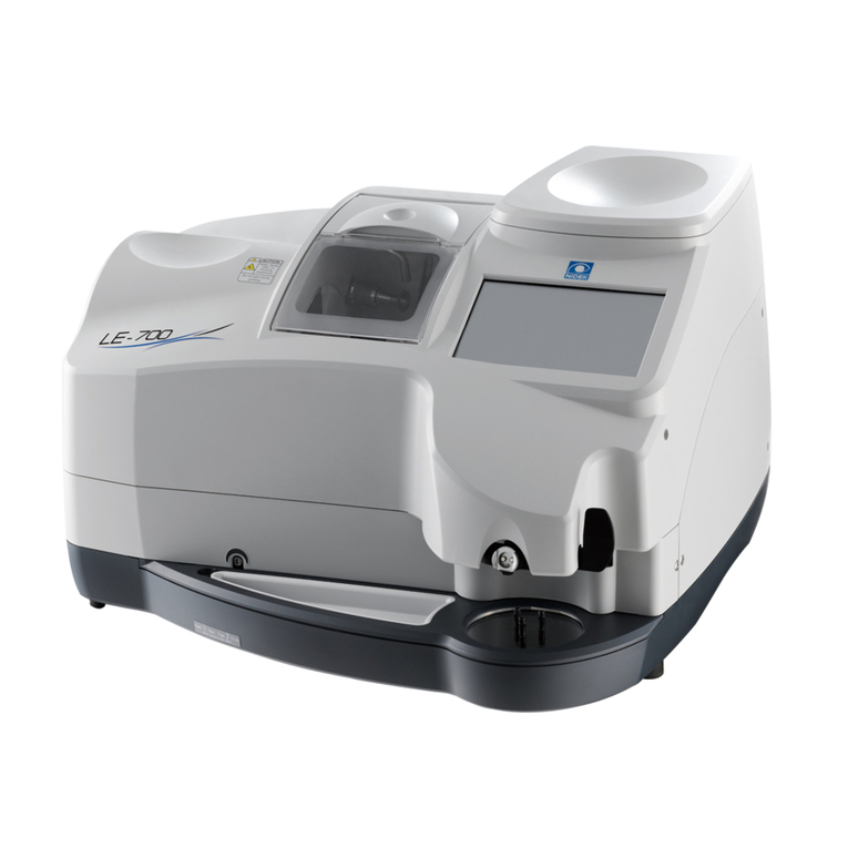
Nidek Medical LE-9000LX User manual

PATTERNLESS EDGER
Model LE-9000LX
OPERATOR’S MANUAL

NIDEK CO., LTD. : 34-14, Maehama, Hiroishi-cho, Gamagori, Aichi 443-0038, Japan
(Manufacturer) Telephone: (81-533) 67-6611
Facsimile: (81-533) 67-6610
NIDEK CO., LTD : 3F Sumitomo Fudosan Hongo Bldg., 3-22-5, Hongo,
(Tokyo Office) Bunkyo-Ku, Tokyo 113-0033, Japan
Telephone: (81-3) 5844-2641
Facsimile: (81-3) 5844-2642
NIDEK INCORPORATED : 47651 Westinghouse Drive, Fremont, California 94539, U. S. A.
(United States Agent) Telephone: (510) 226-5700
Facsimile: (510) 226-5750
NIDEK SOCIETE ANONYME : Europarc 13, rue Auguste Perret, 94042 CRETEIL, France
(Authorized Representative) Telephone: (01) 49 80 97 97
Facsimile: (01) 49 80 32 08
September 2006
40340-P902H
Printed in JAPAN

BEFORE USE OR MAINTENANCE, READ THIS MANUAL.
This Operator’s Manual contains information necessary for the operation of the NIDEK
PATTERNLESS EDGER Model LE-9000LX Type PC, Type PL4, Type PLB, and Type
PLB-2R.
This manual provides operating procedures, cautions for safety, specifications,
accessories, and maintenance. IEC and UL standards are applied in this manual. For
correct use, this manual is needed. Especially, cautions for safety and operating
procedures must be thoroughly understood before using the instrument.
Keep this manual handy to verify use.
If you encounter any problems or have questions about the instrument during use, please
contact NIDEK or your authorized distributor.

Table of Contents
§
1INTRODUCTION ........................................................................................................ 1-1
1.1 Outline of the Product ................................................................................................. 1-1
1.2 Symbol Information .................................................................................................... 1-2
§
2SAFETY ........................................................................................................................ 2-1
2.1 Cautions during Use ................................................................................................... 2-1
2.2 Storage ......................................................................................................................2-3
2.3 Transport ................................................................................................................... 2-3
2.4 Installation .................................................................................................................. 2-4
2.5Wiring ........................................................................................................................ 2-5
2.6 After Use ................................................................................................................... 2-5
2.7 Maintenance and Check ............................................................................................. 2-5
2.8 Disposal ..................................................................................................................... 2-7
2.9 Labels ........................................................................................................................ 2-8
2.10 Safety Function ...................................................................................................... 2-10
§
3CONFIGURATION ..................................................................................................... 3-1
§
4OPERATING PROCEDURES .................................................................................... 4-1
4.1 Operation Flow ......................................................................................................... 4-1
4.2 Preparation ............................................................................................................... 4-3
4.3 Tracings .................................................................................................................... 4-4
4.3.1 Tracing frames ................................................................................................. 4-4
4.3.1.1 Tracing both rims ................................................................................ 4-4
4.3.1.2 Tracing single rim ............................................................................... 4-5
4.3.1.3 Semiauto tracing.................................................................................. 4-5
4.3.1.4 Tracing goggle type frames ................................................................. 4-6
4.3.2 Tracing pattern ................................................................................................ 4-7
4.3.3 Tracing dummy lens ........................................................................................ 4-8
4.3.4 Tracing during processing ............................................................................. 4-10
4.3.5 Stopping tracing ............................................................................................ 4-10
4.3.5.1 Stopping frame tracing ...................................................................... 4-10
4.3.5.2 Stopping pattern or dummy lens tracing ........................................... 4-10
4.4 Layouts ................................................................................................................... 4-11
4.4.1 Selecting processing conditions and inputting layout data ........................... 4-11
4.4.2 Inputting height from lens outline ................................................................. 4-14
4.4.2.1 Layout of bifocal lens ........................................................................ 4-15
4.4.2.2 Layout of progressive power lens ..................................................... 4-16
4.4.3 Eye point layout ............................................................................................ 4-17
4.5 Blocking Lenses ..................................................................................................... 4-18
4.5.1 Blocking in active mode................................................................................ 4-18
Page
4.5.1.1 Blocking progressive power lens .......................................................... 4-18
4.5.2 Blocking in passive mode ................................................................................ 4-19
4.5.3 Blocking bifocal lens ........................................................................................ 4-20
4.6 Processings .............................................................................................................. 4-21
4.6.1 Beveling .......................................................................................................... 4-21
4.6.1.1 Auto processing mode ......................................................................... 4-22
4.6.1.2 Guided processing mode ..................................................................... 4-25
4.6.1.3 Guided processing mode (Tilting function) ............................................ 4-29
4.6.1.4 EX lens processing mode .................................................................... 4-32
4.6.2 Flat (rimless) edging ........................................................................................ 4-36
4.6.2.1 Flat (rimless) edging mode ................................................................... 4-36
4.6.2.2 EX lens flat (rimless) edging mode ....................................................... 4-38
4.6.3 Other processings ........................................................................................... 4-40
4.6.3.1 Processing for frame changing .............................................................. 4-40
4.6.3.2 Processing half-eye lens ....................................................................... 4-43
4.6.3.3 Polishing (Type PL4, PLB, and PLB-2R) ............................................ 4-46
4.6.3.4 Glass soft processing ........................................................................... 4-47
4.6.3.5 Inputting frame tilt angle in flat edging ................................................... 4-48
4.7 Checking Lens Size .................................................................................................. 4-49
4.7.1 Checking lens size ........................................................................................... 4-49
4.7.2 Retouching lens ............................................................................................... 4-49
4.8 Processing the Opposite Lens ................................................................................... 4-51
4.9 Removing the Lens Cup ............................................................................................ 4-51
4.10 Treatment after Daily Use ....................................................................................... 4-52
4.11 Daily Checks .......................................................................................................... 4-53
4.11.1 Daily check before use .................................................................................. 4-53
4.11.2 Daily check after use ..................................................................................... 4-54
4.12 Periodical Check .................................................................................................... 4-55
§
5OTHER FUNCTIONS ................................................................................................. 5-1
5.1 Process Counter ........................................................................................................ 5-1
5.2 Parameter Settings .................................................................................................... 5-2
5.3 Storing Initial Display .............................................................................................. 5-7
5.4 Storing and Calling Up the Traced Data .................................................................. 5-8
5.4.1 When the edger is not connected to the barcode scanner ................................ 5-9
5.4.2 When the edger is connected to the barcode scanner .................................... 5-10
§
6TROUBLESHOOTING GUIDE ................................................................................ 6-1
§
7STORAGE .................................................................................................................... 7-1
Page

§
8MAINTENANCE.......................................................................................................... 8-1
8.1 Wheel Dressing .......................................................................................................... 8-1
8.2 Replacing the Water and Filter (115 V regions) ........................................................... 8-4
8.2.1 Replacing the water (when the optional FP-100 is equipped) .............................. 8-4
8.2.2 Replacing the water (when the optional FP-100 is not equipped) ........................ 8-7
8.3 Replacing the Water and Filter (230 V regions) ........................................................... 8-9
8.4 Replacing Fuses ....................................................................................................... 8-11
8.5 Cleaning the Exterior ................................................................................................ 8-11
8.6 SizeAdjustment ........................................................................................................ 8-12
8.7Adjusting Bevel Position ........................................................................................... 8-13
8.8AdjustingAxis Shift ................................................................................................... 8-15
8.8.1Adjusting axis shift when polishing is not done .................................................. 8-15
8.9Adjusting Lens MarginAllowed for Finishing ............................................................. 8-17
8.10 PD Adjustment ....................................................................................................... 8-18
8.11Adjustment for Polishing .......................................................................................... 8-19
8.11.1 If a part of edge is left unpolished (Type PL4, PLB, and PLB-2R) .................. 8-19
8.11.2 If the front edge or rear edge is left unpolished (Type PLB and PLB-2R) ........ 8-22
8.11.3Axis shift adjustment for polishing (Type PL4, PLB, and PLB-2R) .................. 8-23
8.12 Tracer Calibration ................................................................................................... 8-25
8.13 List of ConsumableArticles .................................................................................... 8-26
§
9SPECIFICATIONS ...................................................................................................... 9-1
§
10 ACCESSORIES.......................................................................................................... 10-1
10.1 NIDEK-type Accessories...................................................................................... 10-1
10.2 WECO-type Accessories ...................................................................................... 10-1
10.3 SANTI-type Accessories ...................................................................................... 10-2
APPENDIX A. SUPPLEMENT ............................................................................................. A-1
A.1 Selection of Tracing................................................................................................ A-1
A.2 Selection of Layout................................................................................................. A-3
A.3 Selection of Blocking ............................................................................................. A-4
A.4 Selection of Processing .......................................................................................... A-5
APPENDIX B. ERROR CODE ............................................................................................. B-1
APPENDIX C. GLOSSARY .................................................................................................. C-1
INDEX ...........................................................................................................End of this manual
Page

1.1 Outline of the Product
This instrument is a fully-automatic lens edger which reads the lens outline of eyeglasses directly
from frames and processes a lens into the shape of frames.
This edger has a processing unit at the center front, a control panel for the processing unit at the
front, a display panel at the right front, a tracing unit, and a control panel for the tracing unit at
the upper side. The tracing unit measures the frame shape, the display panel presents the traced
outline and the lens layout, and the processing unit edges a lens into the desired shape.
Several kinds of processing wheels are provided in the processing unit, and therefore, this instrument
selects the most suitable wheels and the processing sequences according to the lens material to be
processed.
[Lens materials and processing modes]
{: Processing is available.
×: Processing is unavailable.
F: Processing is available (except for glass lenses).
§1
INTRODUCTION
Plastic High index
plastic
Polyca-
rbonate Glass Acrylic
resin Beveling Flat
edging Polishing
PC 䂾䂾 䂾䂾䂾䂾䂾
×
PL4 䂾䂾 䂾䂾䂾䂾䂾
䂔
flat edging
only
PLB 䂾䂾 䂾
×䂾䂾䂾䂔
PLB-2R 䂾 䂾 䂾䂾䂾䂾䂾䂔
Lens material Processing mode
Type

1 - 2
1.2 Symbol Information
This symbol on the body indicates that caution should be taken. It is necessary to refer to
Operator’s Manual before using the instrument.
This symbol means caution for electric shock. The inside of the instrument includes high-
voltage circuit. Do not take off the cover.
This symbol on the power switch indicates that the power is ON.
This symbol on the power switch indicates that the power is OFF.
This symbol indicates the contrast adjustment.
This symbol means the fuse rating.
This symbol indicates that the instrument must be supplied only with alternating current.
This symbol indicates the date of manufacture.
This symbol indicates the manufacturer.
This symbol indicates that this product shall be disposed of in a separate collection of electrical
and electronic equipment in EU.

§2
SAFETY
In this manual, Signal Words are used to designate a degree or level of safety alerting, whose
definitions are as follows.
WARNING: Indicates a potentially hazardous situation which, if not avoided,
could result in death or serious injury.
CAUTION: Indicates a potentially hazardous situation which, if not avoided,
may result in minor or moderate injury or property damage accident.
Besides, even the item of CAUTION could cause a serious result, depending on the
condition. Be sure to follow the manual as the important contents are described.
2.1 Cautions in Use
WARNING
• Never touch the processing wheel when it is turning.
Injury may occur.
• Be sure to keep the soundproof cover closed during processing.
Spray including processing waste may cause eye damage.
• Should abnormal conditions such as cracks or bare areas on the processing wheel have been
found, stop using the instrument immediately and contact NIDEK or your authorized distributor.
Continued use of the instrument may cause the wheel to break and scatter, causing injury.
• Release the chuck by pressing after making sure that the wheels have come to a complete
stop.
If the chuck is released before the wheels have stopped completely and a lens is dropped, it
may contact the turning wheels and its scattering may cause injury.
• Be sure to use this instrument only to process eyeglass lenses.
If this instrument processes any other materials, the processing wheels may be damaged and
cannot perform normal processing. Moreover, the wheels may break and broken pieces may
injurepersonnel

2 - 2
CAUTION
• Never disassemble nor touch the internal structure.
Electric shock or failure of the instrument may occur.
• Never yank the power cord to disconnect it from the wall outlet. Always hold the plug.
This can damage the metal core of the cord and may result in fire, short circuit or electric
shock.
• If the internal wires of the power cord are exposed, power to the instrument is interrupted by
moving the cord, or the plug or cord becomes extremely hot, this indicates that the cord is
damaged.
Immediately remove the plug from the outlet and contact NIDEK or your authorized distributor
for replacement; otherwise, electric shock or fire may result.
• Do not crush or squeeze the power cord with heavy objects such as the instrument itself.
Damage to the cord may result in fire or electric shock.
• Occasionally, clean the prongs of the power plug with a dry cloth.
If dust settles thickly on them, they will become damp, and may cause short circuit or fire.
• Plug in the power cord correctly until its prongs are fully inserted into the socket.
If the instrument is used with an insecure connection, fire may occur.
• In the event that the instrument gives off smoke, or a strange smell, etc., turn off the power and
unplug the power cord. After smoke stops coming out of the instrument, contact NIDEK or
your authorized distributor.
If an instrument which has this kind of abnormal condition is used, fire or electric shock may
occur. In case of fire, use a powder (ABC) extinguisher.
• If the instrument detects any abnormal condition during use, the error code will be shown on the
display panel and the instrument will stop.
Turn the power switch off after confirming the error code.
• Be sure to select the correct lens material with .
If the wrong material is selected, the lens may break or the lifetime of the processing wheel
may be reduced.
• Be sure not to apply excessive stress on the stylus of the tracing unit.
The stylus is easy to bend or break.
• Be careful not to get your fingers caught when chucking (fixing) a lens.

2 - 3
(A) (B)
CAUTION
• When removing the lens cup with the cup remover, hold the lens through the soft cloth.
If you hold the lens with bare hands, the lens edge may hurt your hands.
• Be sure to confirm that wash water (for the inside wall of the processing chamber) and cooling
water (for the wheels) flow properly.
If water does not flow, lenses are not processed properly and the edger may be damaged.
2.2 Storage
CAUTION
• Do not store the instrument where it may get wet or where poisonous gases or liquids are
present.
• Maintain the instrument under the following conditions at transport or storage (packed).
Conditions Temperature: –25 - 70ºC
Humidity: 10 - 100%
Pressure: 700 - 1060 hPa
2.3 Transport
CAUTION
• When moving the instrument, ask for assistance.
Moving the instrument may cause back injury or injury by falling.
• When moving the instrument, hold (A) and (B) for both of the right and left sides. Be
sure not to hold the cover. Only hold the metal part of the underside.
The instrument may be dropped by holding
the cover only and it may cause injury and
malfunction.
• When putting the instrument down, be
careful not to get your fingers caught.
Fingers may get caught between the cabinet
andinstrument injuringthem.
• Use the specified packing material when transporting the instrument to lessen the damage if
dropped.
Excessive vibration or shock to the instrument may cause instrument malfunction.

2 - 4
510
180 153
322
40 140
425
470
Opening A
Position of stage foot
(4 spots)
(Measure: mm)
30
50
Opening B
2.4 Installation
CAUTION
• Use the instrument under the following conditions.
- A dust free environment
- A stable place with no tilt
- A vibration and shock free environment
• Install the instrument where it can be used at the following temperature and humidity.
Use conditions Temperature: 5 - 40ºC
Humidity: Relative humidity does not exceed 50% at a
maximum temperature of 40ºC.
Pressure: 700 - 1060 hPa
• Install the instrument in a location that provides the operation area specified on p. 2-6.
• Install the instrument on the specified table (option) or a stage which is strong enough for the
instrument weight (42 kg).
Vibrations and noises may produce, or normal processings may not be performed.
• Use a stage whose size is larger than the
measurements of the figure to the right. Also
set the adjuster at the foot of the stage so that
the stage can be adjusted without tilt or play.
It is necessary to make openings in the top to
draw the pipe and cord through.
Opening A: For power cord of pump
Opening B: For feedwater pipe and drain pipe
• Do not install the instrument in a place exposed to direct sunlight or where the temperature and
humidityarehigh.
• Install the instrument where pollutants such as corrosive gases, acids, and salts are not present.
Corrosion or malfunction of the instrument may occur.
• Be sure to leave 3 cm or more of space in the rear so that the fan will not be blocked.
If the fan is blocked, the temperature of the inside of the instrument will rise and it may cause
malfunction.

2 - 5
2.5 Wiring
CAUTION
• Do not overload one electrical outlet.
Abnormal heat generation may occur at the outlet in conjunction with the other devices.
• Be sure to use the socket which meets the power specifications.
If the line voltage is too high or low, the instrument may not perform properly. Malfunction or
fire also may occur.
• Be sure to ground the instrument.
Electric shock or fire may occur in the event of failure or electric leakage.
2.6 After Use
CAUTION
• If the instrument will not be used for a long time, unplug the power plug from the wall outlet.
If a thick layer of dust settles on the prongs of the plug, it will become damp, and short circuit
or fire may occur.
• Clean the processing unit after the last use of the day.
If it is left for several days after use, the processing waste becomes settled and hard to remove.
• Turn the power switch off and keep the tracing unit cover and soundproof cover closed when
the instrument is not in use.
If dust settles, it may affect the measurement accuracy or cause malfunction.
2.7 Maintenance and Check
CAUTION
• Be sure to perform the starting inspection before use and finishing inspection after use. It
is recommended to have a periodical inspection every two years.
Inspection is performed by a service person. Contact NIDEK or your authorized distributor.
• Be sure to keep a space large enough for maintenance (see p. 2-6).
Working in a tight place may cause possible injury.

2 - 6
Approx.500mm
Maintenance
Operationarea
area
Approx.500mm
Approx.500mm
Approx.485mm
Approx.500mm
Approx.1000mm
Approx.520mm
CAUTION
• Be sure to use the specified fuses for replacement.
If not, fire may occur.
• Be sure to use the suitable dressing stick for wheel dressing.
If not, the wheel may be damaged and normal processing cannot be performed.
• Be sure to replace a dressing stick worn some 4 cm with a new one.
It is hard to hold the shortened dressing stick, and hand injury may occur.
• Be sure to wear protective glasses for wheel dressing.
Spray including processing waste may cause eye damage.
• Never dress the roughing wheel for plastic lenses.
The wheel may be damaged.
• In the dressing mode, the cover sensor is released and the wheels turn with the soundproof
cover open. While dressing, work with special care.
[Operation area/ Maintenance area]

2 - 7
CAUTION
• Be sure to use the specified stocking filter only.
If not, the filter or water supply pipe may become clogged.
• The stocking filter is disposable. Do not reuse it.
A filter which has a rip or run in it does not function as a filter, and therefore, the water supply
pipe may become clogged.
• Never use an organic solvent such as paint thinner to clean the exterior of the instrument.
This could affect the surface.
2.8 Disposal
NOTE
• Follow local governing ordinances and recycling plans regarding disposal or recycling of
device components.
• When disposing packing materials, sort them by material, and follow local governing
ordinances and recycling plans.
• When disposing of the wastes of lenses, follow local governing ordinances as
noncombustibles.

2 - 8
2.9 Labels
The following labels provide safety information about each part.
<Front view>
<Rear view>
( (
((
6#8
/#
9#40+0)
4+5-1((+4'
4'2.#%'(75'
#5/#4-'&
4+537'&+0%'0&+'
4'/2.#%'4.'(75+$.'
%1//'+0&+37'574
.#016+%'
or
or
(115 V regions only)

2 - 9
<Top view>
or
or

2 - 10
2.10 Safety Function
For safety use, various functions are provided.
[Soundproof cover check function at processing start]
Lens processing does not start unless the soundproof cover is closed.
CAUTION
• If the soundproof cover is opened during processing, the instrument does not stop. Be sure not
to open the soundproof cover during processing since it is hazardous.
Besides, open the soundproof cover only after making sure that the wheels have come to a
complete stop.
[Stop key]
This is a key to stop processing. Processing can be stopped immediately under abnormal conditions.
To switch off the system after stop, turn the power switch OFF. To restart processing after stop,
press .
[Self-check function]
Operation conditions are checked all the time by this function. If something unusual occurred
in the instrument, the system will immediately stop and display the error number which
indicates the error content on the display panel.

2 - 11

[Whole system]
[Rear side of the main body]
RS-232C interface connector
Connector for barcode scanner
Outlet for pump 1
Outlet for pump 2
Power switch
Contrast control
Inlet
Cooling fan
Table
Tracing unit cover
Display panel
Control panel
for tracing unit
Control panel
for processing unit
Drawer
§3
CONFIGURATION
Soundproof cover
Table of contents
Other Nidek Medical Edger manuals

Nidek Medical
Nidek Medical SE-9090 Express User manual

Nidek Medical
Nidek Medical SE-9090 Supra User manual

Nidek Medical
Nidek Medical LE-700 User manual

Nidek Medical
Nidek Medical Le 1000 User manual

Nidek Medical
Nidek Medical LE-9000SX User manual

Nidek Medical
Nidek Medical LE-700 User manual

Nidek Medical
Nidek Medical LE-9000EX Express User manual

Nidek Medical
Nidek Medical LE-700 Instruction sheet

Nidek Medical
Nidek Medical ME 1200 Service manual

Nidek Medical
Nidek Medical Lex 1000 User manual