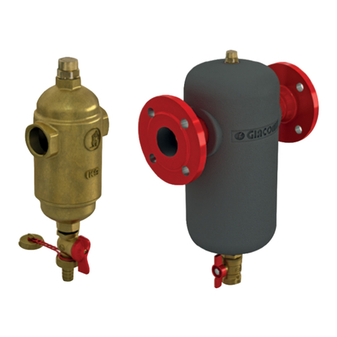
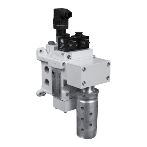
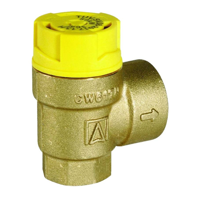
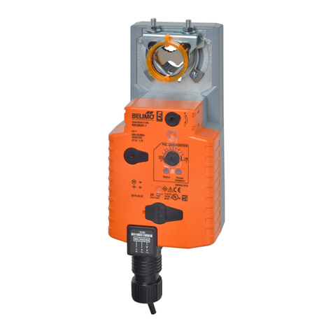
NieRuf EV01 User manual

Operating instructions
Solenoid valve, series
Type EV01, MV01
Type MV02
Type EV03, MV03
Type EV04, MV04
Type EV05, MV05
Type EV06, MV06
Type EV07, MV07
Type EV08, MV08
Type EV09, MV09
Type FV01

Imprint
2/23 OPERATING INSTRUCTIONS FOR METAL SOLENOID-VALVES Index: 0
Imprint
Manufacturer NieRuf GmbH
Zeppelinstr. 11
74354 Besigheim
Germany
Phone: +49 (0) 7143 96669 00
Fax: +49 (0) 7143 96669 01
E-mail: info@nieruf.de
Website: www.nieruf.de
Published by NieRuf GmbH
Printed by NieRuf GmbH
Translation These operating instructions in English are a translation of the
original German operating instructions. Operating
instructions in other languages are also translations of the original
German operating instructions. In the event of discrepancies
between the different versions, the information contained in the
original operating instructions in German shall apply.
Read carefully before use.
Store in a safe place for future reference.
Subject to technical modifications.

Table of contents
3/23 OPERATING INSTRUCTIONS FOR METAL SOLENOID-VALVES Index: 0
Table of contents
1 About these instructions .................................................................................................................... 5
1.1 Target group ................................................................................................................................ 5
1.2 Other applicable documents ....................................................................................................... 5
1.3 Guarantee .................................................................................................................................... 5
1.4 Warning notices and symbols ..................................................................................................... 6
2 General safety instructions ................................................................................................................ 7
2.1 Intended use ................................................................................................................................ 7
2.2 General safety instructions ......................................................................................................... 7
2.2.1 Duties of the operator .......................................................................................................... 7
2.2.2 Duties of the personnel ........................................................................................................ 8
2.3 Special dangers ............................................................................................................................ 8
2.3.1 Duties of the personnel ........................................................................................................ 8
3 Design and function ............................................................................................................................ 9
3.1 Type label .................................................................................................................................... 9
3.2 Description .................................................................................................................................. 9
3.3 Design and dimensions .............................................................................................................. 10
3.3.1 Type EV01 and MV01 ......................................................................................................... 10
3.3.2 Type MV02 ......................................................................................................................... 10
3.3.3 Type EV03 and MV03 ......................................................................................................... 10
3.3.4 Type EV04 and MV04 ......................................................................................................... 11
3.3.5 Type EV05 and MV05 ......................................................................................................... 11
3.3.6 Type EV06 and MV06 ......................................................................................................... 11
3.3.7 Type EV07 and MV07 ......................................................................................................... 12
3.3.8 Type FV01 ........................................................................................................................... 12
3.3.9 Type EV08 and MV08 ......................................................................................................... 12
3.3.10 Type EV09 and MV09 ....................................................................................................... 12
4 Transport, storage and disposal ....................................................................................................... 13
4.1 Unpacking .................................................................................................................................. 13
4.2 Transport ................................................................................................................................... 13
4.3 Storage ...................................................................................................................................... 13
4.4 Disposal ..................................................................................................................................... 13
5 Installation and connection .............................................................................................................. 14
5.1 Preparing the installation .......................................................................................................... 14

1 About these instructions
4/23 OPERATING INSTRUCTIONS FOR METAL SOLENOID-VALVES Index: 0
5.1.1 Checking conditions of use ................................................................................................. 14
5.2 Planning pipelines ..................................................................................................................... 14
5.2.1 Designing pipelines ............................................................................................................. 14
5.3 Fitting the valve to a pipeline .................................................................................................... 15
5.3.1 Threaded connection ......................................................................................................... 15
5.3.2 Connection with flange ...................................................................................................... 15
5.4 Electrical connection ................................................................................................................. 16
5.4.1 Plug assignment .................................................................................................................. 16
5.5 Carry out a pressure check ........................................................................................................ 16
6 Operation ......................................................................................................................................... 17
6.1 Commissioning .......................................................................................................................... 17
7 Maintenance and repairs ................................................................................................................. 18
7.1 Maintenance ............................................................................................................................. 18
7.2 Repairs ....................................................................................................................................... 18
7.2.1 Removing valves ................................................................................................................. 19
7.2.2 Replacing solenoid coils ...................................................................................................... 19
7.3 Spare parts ................................................................................................................................ 20
7.4 Returns ...................................................................................................................................... 20
7.5 Packaging ................................................................................................................................... 20
8 Fault elimination .............................................................................................................................. 21
9 Appendix .......................................................................................................................................... 22
9.1 Technical data ........................................................................................................................... 22
9.2 Circuit diagrams ......................................................................................................................... 22
9.2.1 Circuit diagrams Type EV01 /-03 and MV01 /-02 /-03 ....................................................... 22
9.2.2 Circuit diagrams Type EV04 /-05 /-07, MV04 /-05 /-07 and FV01 ...................................... 22
9.2.3 Circuit diagrams Type EV06 and MV06 .............................................................................. 22
9.2.4 Circuit diagrams Type EV08 /-09 and MV08 /-09 ............................................................... 22
9.3 Declaration of conformity ......................................................................................................... 23

1 About these instructions
5/23 OPERATING INSTRUCTIONS FOR METAL SOLENOID-VALVES Index: 0
1 About these instructions
These instructions
§ Are part of the valve
§ Are applicable for Series EV01-03-04-05-06-07-08-09, MV01-02-03-04-05-06-07-08-09 und
FV01.
§ Describe the safe and correct operation of the valve
§ Are available for downloading from the website
1.1 Target group
Operator
§ These instructions must be kept available at the place of use, including for future
applications.
§ Employees must be encouraged to read and observe these instructions.
§ Additional country-specific or plant-specific regulations and rules must be observed.
Personnel
§ Skilled workers with additional qualifications for installing the respective pipeline system.
§ Electrician
§ Read these instructions as well as all other applicable documents.
1.2 Other applicable documents
§ Data sheet
If not available, the data sheet must be requested from the manufacturer.
1.3 Guarantee
NieRuf GmbH accepts no liability if operators or third parties:
§ Disregard this document
§ Do not use the product properly
§ Carry out interventions of any type whatsoever to the product (alterations, modifications,
etc.)
Malfunctions that can be attributed to contamination or wear, as well as wearing parts (e.g. seals),
are not covered by the warranty.

1 About these instructions
6/23 OPERATING INSTRUCTIONS FOR METAL SOLENOID-VALVES Index: 0
1.4 Warning notices and symbols
DANGER
High risk
Denotes an imminent danger that will result in serious injuries or
death if not avoided.
WARNING
Medium risk
Denotes a possibly dangerous situation that may result in serious
injuries or death if not avoided.
CAUTION
Low risk
Denotes a possibly dangerous situation that may result in slight or
minor injuries if not avoided.
NOTE
Instruction
Denotes a possibly dangerous situation that may cause damage to
property if not avoided.

2 General safety instructions
7/23 OPERATING INSTRUCTIONS FOR METAL SOLENOID-VALVES Index: 0
2 General safety instructions
NOTE
Liability
The manufacturer accepts no liability for damage resulting from the
failure to observe the complete documentation.
2.1 Intended use
§ The valve must be used exclusively for shutting off pipelines carrying suitable media
§ Observe the operating limits
§ Use the armature exclusively for media that are free of solid matter
2.2 General safety instructions
NOTE
Information
Read and observe the following regulations before carrying out any
activities.
2.2.1 Duties of the operator
Safety-conscious working
§ Only operate the valve if it is in technically flawless condition, for its intended application and
keeping safety and potential dangers in mind in accordance with these instructions.
§ Ensuring adherence and supervision:
- Intended use
- Statutory or other safety and accident-prevention regulations
- Safety regulations for handling dangerous substances
- Applicable standards and directives of the respective country of use
§ Supply personal protective equipment

2 General safety instructions
8/23 OPERATING INSTRUCTIONS FOR METAL SOLENOID-VALVES Index: 0
Personnel qualifications
§ Make sure that personnel tasked with carrying out activities using the valve have read and
understood these instructions and all other applicable documents before starting work,
especially safety, maintenance and repair information.
§ Manage the responsibilities, competencies and supervision of personnel.
§ Only qualified technical personnel are to be permitted to carry out the following work:
- Installation, repair and maintenance work
- Work on the electrical system
§ Only allow trainee personnel to work on the valve under the supervision of qualified
technical personnel
WARNING
Unqualified personnel
Improper handling can result in serious personal injuries or damage
to property. The work described here must only be carried out by
qualified personnel.
2.2.2 Duties of the personnel
§ Instructions on the valve itself should be observed and kept in a legible state, e.g. type label.
§ Only work on the valve if the following prerequisites are met:
- System is drained
- System is flushed
- System is de-pressurised
- System is cooled
- System is secured against reactivation
§ Do not make modifications to the device
2.3 Special dangers
2.3.1 Duties of the personnel
§ When handling dangerous media (e.g. hot, flammable, explosive, toxic, harmful,
environmentally hazardous), always observe the safety regulations governing the handling of
dangerous substances.
§ During all work on the valve, wear personal protective equipment.
§ Leakages and residues must be safely contained and disposed of in an environmentally-safe
manner.

3 Design and function
9/23 OPERATING INSTRUCTIONS FOR METAL SOLENOID-VALVES Index: 0
3 Design and function
3.1 Type label
Layout of the type label:
1 Article
2 Connection
3 Nominal diameter, voltage, function
4 Medium temperature
5 Pressure range
6 Commission number
7 Serial number
3.2 Description
The metal valve is a seat valve fitted with a diaphragm seal and is used for opening and closing
pipelines. It is fully automatic and glandless and therefore practically maintenance-free.
§ Available as normally closed (NC) or normally open (NO) variants.
§ Connector complies with DIN EN 175301-803 form A.
o Types EV01 / -09 and MV01 / -09 with DIN EN 175301-803 form B
§ Flow direction as per direction arrow on the valve body.
§ Valves are not suitable for back pressure.
§ Fitting position:
- Solenoid coil ideally at the top.
- Fit valve horizontally or vertically into the line.
Type EV01 /-03 and MV01 /-02 /-03
The valve is a direct-controlled seat valve. No differential pressure is required for opening or closing.
Type EV04 /-05 and MV04 /-05
The valve is servo-controlled and requires a differential pressure to open and close.
Type EV04/MV04 requires a differential pressure of 0.1 bar between the inlet and outlet.
Type EV05/MV05 requires a differential pressure of 0.5 bar between the inlet and outlet.
Type EV06 /-07, MV06 /-07 and FV01
The valve is servo-controlled with positive lift. No differential pressure is required for opening and
closing.
Type EV08 /-09 and MV08 /-09
The valve is a direct-controlled seat valve. No differential pressure is required for opening or closing.

3 Design and function
10/23 OPERATING INSTRUCTIONS FOR METAL SOLENOID-VALVES Index: 0
3.3 Design and dimensions
3.3.1 Type EV01 and MV01
3.3.2 Type MV02
3.3.3 Type EV03 and MV03
POS
Designation
Material
1
Connector
Plastic
2
Coil housing
Plastic or metal
3
Valve body
Brass or stainless steel
Seal material
NBR, EPDM or FKM
POS
Designation
Material
1
Connector
Plastic
2
Coil housing
Plastic or metal
3
Valve body
Brass
Seal material
NBR, EPDM or FKM
POS
Designation
Material
1
Connector
Plastic
2
Coil housing
Plastic or metal
3
Valve body
Brass or stainless steel
Seal material
NBR, EPDM or FKM

3 Design and function
11/23 OPERATING INSTRUCTIONS FOR METAL SOLENOID-VALVES Index: 0
3.3.4 Type EV04 and MV04
3.3.5 Type EV05 and MV05
3.3.6 Type EV06 and MV06
POS
Designation
Material
1
Connector
Plastic
2
Coil housing
Plastic or metal
3
Cover
Brass or stainless steel
4
Valve body
Brass or stainless steel
Seal material
NBR, EPDM or FKM
POS
Designation
Material
1
Connector
Plastic
2
Coil housing
Plastic or metal
3
Cover
Brass or stainless steel
4
Valve body
Brass or stainless steel
Seal material
NBR, EPDM or FKM
POS
Designation
Material
1
Connector
Plastic
2
Coil housing
Plastic or metal
3
Cover
Brass or stainless steel
4
Valve body
Brass or stainless steel
Seal material
NBR, EPDM or FKM

3 Design and function
12/23 OPERATING INSTRUCTIONS FOR METAL SOLENOID-VALVES Index: 0
3.3.7 Type EV07 and MV07
3.3.8 Type FV01
POS
Designation
Material
1
Connector
Plastic
2
Coil housing
Plastic or metal
3
Cover
stainless steel
4
Valve body
stainless steel
Seal material
NBR, EPDM or FKM
3.3.9 Type EV08 and MV08
3.3.10 Type EV09 and MV09
POS
Designation
Material
1
Connector
Plastic
2
Coil housing
Plastic or metal
3
Cover
Brass or stainless steel
4
Valve body
Brass or stainless steel
Seal material
NBR, EPDM or FKM
POS
Designation
Material
1
Connector
Plastic
2
Coil housing
Plastic or metal
3
Valve body
Brass or stainless steel
Seal material
NBR, EPDM or FKM
POS
Designation
Material
1
Connector
Plastic
2
Coil housing
Plastic or metal
3
Cover
Brass or stainless steel
4
Valve body
Brass or stainless steel
Seal material
NBR, EPDM or FKM

4 Transport, storage and disposal
13/23 OPERATING INSTRUCTIONS FOR METAL SOLENOID-VALVES Index: 0
4 Transport, storage and disposal
4.1 Unpacking
§ On receipt of the armature, unpack it, check it for signs of transport damage and ensure that
it is complete.
§ Transport damage or missing components must be reported to the manufacturer
immediately.
§ Make sure that the type label information matches the order and design data.
§ When installing the product, dispose of the packaging material in accordance with the
applicable local regulations.
4.2 Transport
§ Wherever possible, transport the valve in the original packaging
§ Lift the valve by hand for transport purposes (see data sheet for weight information)
4.3 Storage
NOTE
Improper storage can cause damage to property
Store the valve properly.
You must ensure that the storage location fulfils the necessary conditions, such as:
§ Dry
§ Frost-free
§ Free from vibrations
§ No direct sunlight
§ Storage temperature range +10°C to +50°C
4.4 Disposal
The valve must be disposed of in accordance with the applicable local regulations.
NOTE
Contamination
Plastic components may be contaminated by toxic or radioactive
media to such an extent that cleaning is not sufficient.
WARNING
Danger of poisoning and environmental damage from the medium
During all work on the armature, wear personal protective
equipment.
Prior to disposing of the valve, contain any leaking medium and
dispose of it separately in accordance with the applicable local
regulations. Medium residues in the armature must be neutralised.
Dismantle plastic parts and dispose of them in accordance with the
applicable local regulations.

5 Installation and connection
14/23 OPERATING INSTRUCTIONS FOR METAL SOLENOID-VALVES Index: 0
5 Installation and connection
5.1 Preparing the installation
5.1.1 Checking conditions of use
§ Make sure that the valve design is suitable for the intended use:
- Materials used
- Medium
§ Ensures the necessary conditions of use
- The resistance of the materials used for the body and seals against the medium
- Media temperature
- Operating pressure
§ Agree any other use with the manufacturer
5.2 Planning pipelines
5.2.1 Designing pipelines
WARNING
Danger of poisoning and environmental damage from the medium
Leakage due to leaks caused by impermissible pipeline forces.
Make sure that no tensile or compressive forces and no bending
moments act on the armature.
§ Plan pipelines with safety in mind
- Ensure there are no tensile or compressive forces
- Ensure there are no bending moments
- Compensate for changes in length caused by temperature fluctuations
- Observe the direction of flow
- Pay close attention to the fitting position and direction of the valve
- Apply suitable measures to prevent pressure surges
§ Dimensions (3.3 Design and dimensions)
§ Fit dirt traps to ensure proper functioning

5 Installation and connection
15/23 OPERATING INSTRUCTIONS FOR METAL SOLENOID-VALVES Index: 0
5.3 Fitting the valve to a pipeline
WARNING
De-pressurised fitting.
Only fit the valve to de-pressurised pipelines.
WARNING
Danger of poisoning and environmental damage from the medium
Leakage due to incorrect installation.
Installation work on the pipelines must only be carried out by skilled
workers who are trained for the respective pipeline system.
NOTE
Improper installation of the valve can cause damage to property
Fit the armature horizontally or vertically.
Ideally, fit the armature with the solenoid coil pointing upwards.
NOTE
Contamination in the valve can cause damage to property
Make sure that no contamination can enter the armature.
Flush the pipeline with a neutral medium.
The procedure used to fit the armature is determined by the type of connection to the pipeline.
5.3.1 Threaded connection
§ Screw the threaded connection onto the pipe in accordance with the applicable standard.
§ Use suitable sealing materials depending on the design and intended purpose.
5.3.2 Connection with flange
§ Check that the sealing face is free of damage and clean.
§ Carefully align the flange in front of the threaded joint.
§ Centre the seals (use suitable sealing material).
§ Connect the valve flange and pipe flange with the seal and suitable bolts.
§ Tighten the bolts cross-wise. Use all of the flange holes!
§ Only use permissible joining elements.

5 Installation and connection
16/23 OPERATING INSTRUCTIONS FOR METAL SOLENOID-VALVES Index: 0
5.4 Electrical connection
DANGER
Danger to life due to electric shock
Only allow an electrician to work on the electrical system.
Switch off the power supply to the system and secure it to prevent it
from being accidentally switched on again.
Connect protective conductors.
§ Before making the electrical connection, check that the current type and voltage are correct
(see data sheet).
§ Make sure that the device plug connection is protected against constant moisture. If
necessary, fit a protective cover.
§ Connect the cable to the device.
§ Connect protective conductors.
§ Insert device plug into connector on the valve.
5.4.1 Plug assignment
HINWEIS
Plug
Plug according to DIN EN 175301-803.
1 Supply voltage
2 Supply voltage
3 Protective earth conductor
5.5 Carry out a pressure check
NOTE
Medium pressure check
Carry out the pressure check using a neutral medium (e.g. water).
§ Pressurise the valve. When doing so, ensure that:
- Test pressure < permissible system pressure
- Test pressure < 1.5 PN
§ Check that the valve is leak-tight.

6 Operation
17/23 OPERATING INSTRUCTIONS FOR METAL SOLENOID-VALVES Index: 0
6 Operation
6.1 Commissioning
The valve must be correctly assembled and connected.
WARNING
Danger of poisoning and environmental damage from the medium
Leakage due to leaks caused by impermissible pipeline forces.
Make sure that no tensile or compressive forces and no bending
moments act on the armature.
NOTE
Overheating will destroy the alternating voltage solenoids
When commissioning the valve equipped with an alternating voltage
solenoid, make sure that the solenoid coil is mounted on the plunger
guide.
§ On the Types EV04-05 and MV04-05, make sure that the required differential pressure is
applied between the valve inlet and valve outlet.
§ After it is first exposed to pressure and operating temperatures, check that the valve is leak-
tight.

7 Maintenance and repairs
18/23 OPERATING INSTRUCTIONS FOR METAL SOLENOID-VALVES Index: 0
7 Maintenance and repairs
WARNING
Risk of injury and poisoning by media
During all work on the valve, wear personal protective equipment.
7.1 Maintenance
§ Visual and functional inspection (quarterly):
- No change in normal operating states
- Leak-tightness
- No unusual operating noises and vibrations
§ If necessary, clean valve with a damp cloth.
NOTE
Adjust maintenance intervals
The maintenance intervals must be adjusted in line with the
applicable operating conditions. This is the responsibility of the
operator.
7.2 Repairs
DANGER
Danger to life due to electric shock
Only allow an electrician to work on the electrical system.
WARNING
Risk of injury and poisoning due to dangerous or hot media
During all work on the valve, wear personal protective equipment.
Any medium leaks must be safely contained and disposed of in an
environmentally-safe manner.
WARNING
Risk of injury during disassembly work
Wear protective gloves; components can become extremely sharp as
a result of wear or damage.
Components fitted with springs must be removed with great care as
the spring tension can cause components to be hurled out.

7 Maintenance and repairs
19/23 OPERATING INSTRUCTIONS FOR METAL SOLENOID-VALVES Index: 0
7.2.1 Removing valves
§ Make sure that:
- System is drained
- System is flushed
- System is de-pressurised
- System is cooled
- System is secured against reactivation
§ Remove valve from the pipeline.
§ If necessary, decontaminate valve.
- Empty spaces in the valve may still contain medium.
7.2.2 Replacing solenoid coils
3
4
5
2
1
1. Loosen bolt (1) and remove device plug (2) from the valve.
2. Unscrew nut (3) and remove washer (4).
4. Remove solenoid coil (5). Dispose of faulty solenoid coil.
5. Fit new solenoid coil (5).
6. Refit the individual parts in reverse order.
7. Connect armature to power supply (5.4 Connecting the armature to the power supply).
8. Conduct pressure check (5.5 Conducting the pressure check).

7 Maintenance and repairs
20/23 OPERATING INSTRUCTIONS FOR METAL SOLENOID-VALVES Index: 0
7.3 Spare parts
§ Keep the following information ready for ordering spare parts.
- Valve type
- Article number
- Nominal pressure and diameter
- Materials of body and seals
§ Only use spare parts supplied by NieRuf GmbH.
7.4 Returns
§ Seal all valve openings (e.g. with protective film).
§ A clearance declaration must be completed and enclosed with the returns.
7.5 Packaging
NOTE
Unsuitable packaging
The valve may be damaged if unsuitable packaging is used.
Always use the original packaging and handle the product with care.
NieRuf GmbH accepts no responsibility for damage caused by the use of unsuitable packaging!
This manual suits for next models
17
Table of contents

