manuals.online logo
Brands
  1. Home
  2. •
  3. Brands
  4. •
  5. Siemens
  6. •
  7. Control Unit
  8. •
  9. Siemens RM-30U User manual

Siemens RM-30U User manual

Wiring Instructions
Models RM-30U/RM-30RU
Releasing Device Modules
Fire Safety
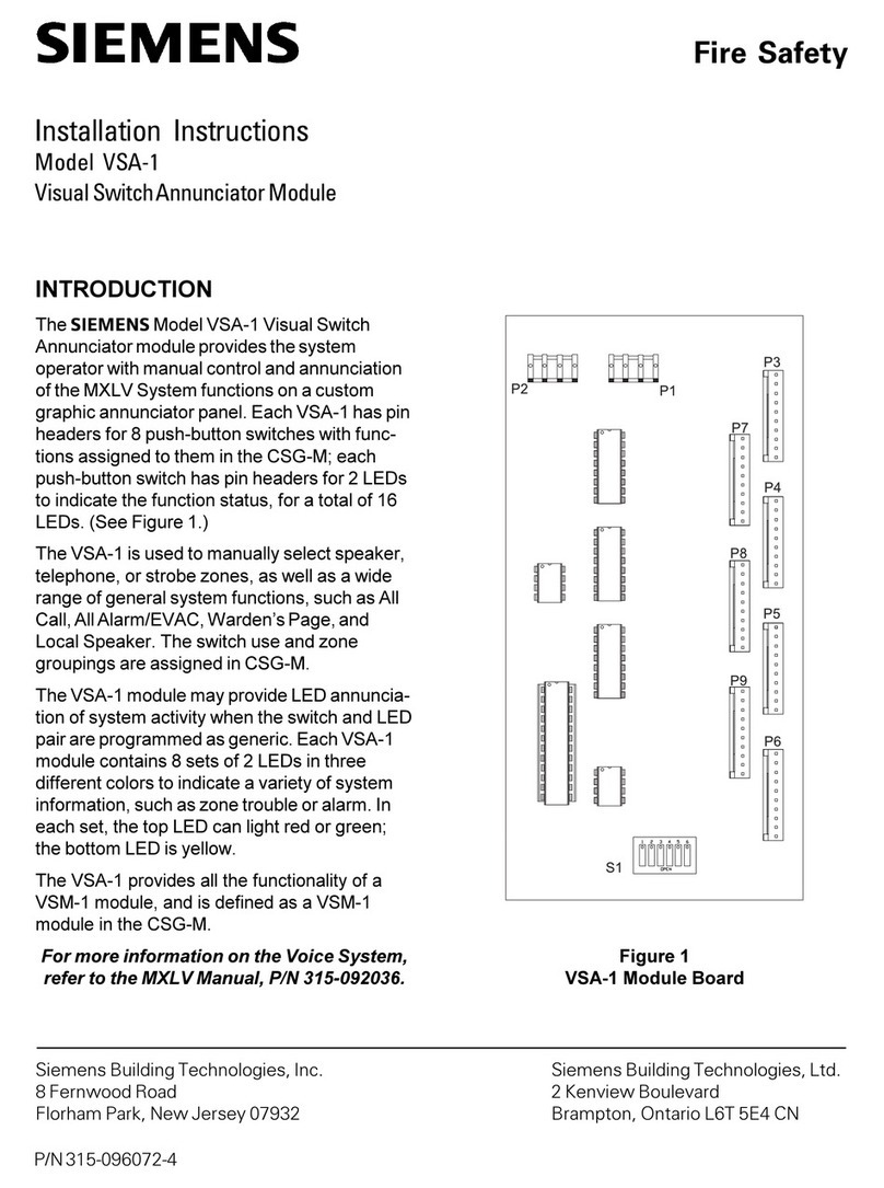
Description
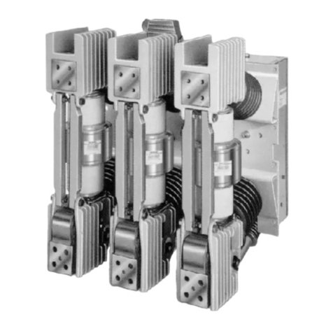
The Releasing Device Modules, Models RM-30U and
RM-30RU are designed to operate and supervise
solenoid valves or relays used for release of
extinguishing systems and to operate and supervise
relays used for door closing/opening or fan control.
The RM-30U and RM-30RU are functionally the
same except that the RM-30RU incorporates three
(3) series resistors that are used to adjust the
resistance of the circuit to compensate for varying
numbers of solenoids.
Release logic and subsequent activation of the
modules are governed by appropriate zone and
control modules in the System 3 control panel.
The modules are suitable for continuous duty when
used with continuous duty solenoids.
Dual input signals are required for activation of these
modules and a release takes place when a high
going signal is present on both of the input terminals.
These input signals are compatible with the outputs
available from the System 3 zone and control
modules. All agent release logic, time delays, etc.,
are performed ahead electrically of the RM-30U/
30RU by utilizing such System 3 modules as : ZU-35
Zone Module, PM-31 Program Matrix, TL-30U Timer,
and SR-32 Relay Module. The separate release
power input terminals extend the modules’ versatility
and reduces the load on the 10 conductor system bus.
A circuit disconnect switch is provided to deactivate
the module during servicing of the system. When the
switch is in the off position, a local supervisory LED
will be illuminated and an audible will sound.
The modules are provided with a yellow LED trouble
indicator to show an open release circuit condition
when the system is not in alarm. The LED indicator
can be lamp tested from the control panel. In addition
all wiring is monitored by the control panel for ground
faults. The module is also provided with a
supervisory LED, buzzer and silence switch. As
noted above, activating the disconnect switch
activates the supervisory signal. When there is no
disconnect condition and the supervisory silence
switch is in the silence condition, a trouble signal is
activated. The modules are placement supervised,
providing a trouble signal on removal from the
system.
Electrical Information
Module current requirement:
Normal supervisory - 6mA @ 24VDC
Released energized - 1.5A maximum @ 24VDC
Maximum line resistance - 3 ohms for typical
approved load.
Siemens Building Technologies, Inc.
8 Fernwood Road
Florham Park, New Jersey 07932
Siemens Building Technologies, Ltd.
2 Kenview Boulevard
Brampton, Ontario L6T 5E4 Canada
P/N 315-085100-14
RM-30U
TC-30U
CP-35
6
42
6
5
5
4
3
2
1
+
_
INPUT POWER
(SEE NOTE 1)
3 OHMS MAX
TOTAL LINE RESISTANCE OF
DISCHARGE DEVICE CIRCUIT
CONNECTING WIRES
OPERATING SOLENOID
OR OTHER APPROVED LOAD
(SEE NOTE 1 AND TABLE 2)
CLASS B CONNECTED RELEASING DEVICE CIRCUIT
POLARITY SHOWN IN SUPERVISORY CONDITION
SUPV: 1.0 VDC, 5mA
ACTIVATED: 24 VDC REGULATED, 1.5mA MAX
ALARM ACTIVATED INPUT
24 VDC FULLWAVE UNFILTERED
RECTIFIED, 21mA (MAX) FROM CP-35
(AS SHOWN) OR EQUIVALENT
ACTUATION INPUT
24 VDC
,
3mA (MAX) FROM
CP-35, TERMINAL 42,
ZU-35, TERMINAL 1 OR 7,
OR TL-30U, TERMINAL 3
FULLWAVE
UNFILTERED RECTIFIED
THIS CONNECTION MUST
BE MADE TO PROVIDE
ACTUATION POWER
DURING ALARM ONLY
3A FUSE
RM-30RU
TC-30U
CP-35
6
42
6
5
5
4
3
2
1
+
_
JUMPERS
(3 PLACES--
SEE TABLE 1)
INPUT POWER
(SEE NOTE 1)
3 OHMS MAX
TOTAL LINE RESISTANCE OF
DISCHARGE DEVICE CIRCUIT
CONNECTING WIRES
SERIES CONNECTED OPERATED
SOLENOID(S) RATED 6 VDC EACH
OR OTHER APPROVED LOAD
(SEE NOTES 1 AND 2)
ALARM ACTIVATED INPUT
24 VDC
21mA (MAX) FROM CP-35
(AS SHOWN) OR EQUIVALENT
FULLWAVE UNFILTERED
RECTIFIED,
ACTUATION INPUT
24 VDC FULLWAVE
UNFILTERED RECTIFIED,
3mA (MAX) FROM
CP-35, TERMINAL 42,
ZU-35, TERMINAL 1 OR 7,
OR TL-30U, TERMINAL 3
THIS CONNECTION MUST
BE MADE TO PROVIDE
ACTUATION POWER
DURING ALARM ONLY
3A FUSE
LOAD
ADJUST
JUMPERS
CLASS B CONNECTED RELEASING DEVICE CIRCUIT
POLARITY SHOWN IN SUPERVISORY CONDITION
SUPV: 1.0 VDC, 5mA
ACTIVATED: 24 VDC REGULATED, 1.5mA MAX
NOTES for RM-30RU:
1. Operating solenoids, relay, or other approved loads operate
from a 24 VDC source. Use Battery Transfer Modules BC-35
or DC Program Plug JP-D in P2 of the CP-35.
2. The RM-30RU Releasing Device Module may be used to
activate up to four 6 VDC solenoids. Table 1 describes the
only acceptable combinations of solenoids and/or resistors.
Any other combination not described in Table 1 is not
permitted.
3. Solenoid supervised for open only.
4. All terminals are non-power limited. For wiring instructions
refer to the EB-31/-32/-33/-35 Installation and Power Limited
Wiring Instructions, P/N 315-093680. If power limited wiring
is desired use the PLM-35, P/N 315-093495.
5. For releasing diagram connections of RM-30RU, refer to
P/N 315-049675. The abort switch can have precedence
over the manual release function, or the manual release can
have precedence over the abort switch.
1ELBAT
noitacilppA snemeiS ledoM rodneV rebmuNtraP
forebmuN niseciveD seireS
forebmuN srotsiseR seireSni
f
orebmuN srepmuJ tuCot
1002APFN )ae722-CFH( 6-CEYPCOCSA 6-235812VH CDV6enO33
6-CEYPCOCSA 6-235812VH CDV6owT22
6-CEYPCOCS
A6-235812VH CDV6eerhT11
6-CEYPCOCSA *6-235812VH CDV6ruoF00
21-CEYPCETITPANS **5F4A-BN2-A3282 CDV21owT00
42-CEYPCETITPA
NS 6F4A-BN2-A3282 CDV42enO00
.desuebtsumsdionelosV6detcennocseiresruoF* CDV6ehtfonoitanibmocynahtiwdionelos
CDV21enoximotdettimreptonsitI** .srotsiserro/dnasdionelos
2ELBAT
noitacilppA snemeiS ledoM rodneV rebmuNtraP
forebmuN nisdioneloS seireS
31APFN A/N701A0128TOCSACDV42enO
)eg
uleDnoitcaerP( A/N701A0128ROCSACDV42enO
1002APFN6-CEYPC6-235812VHOCSACDV6enO
)ae722-CFH( 6-CEYPC6-235812VHOCSACD
V6owT
6-CEYPC6-235812VHOCSACDV6eerhT
6-CEYPC*6-235812VHOCSACDV6ruoF
21-CEYPC**5F4A-BN2-A3282ETITPANSCDV21owT
42
-CEYPC6F4A-BN2-A3282ETITPANSCDV42enO
.dettimreptonsielbatehtnidebircsedtondionelosynA .desuebtsumsdionelo
sV6detcennocseiresruoF* 6ehtfonoitanibmocynahtiwdionelosCDV21enoximotdettimreptonsitI** .sdionelosCDV
NOTES for RM-30U:
1. Operating solenoids, relay, or other approved loads operate
from a 24 VDC source. Use Battery Transfer Modules BC-35
or DC Program Plug JP-D in P2 of the CP-35.
2. For NFPA 13 Automatic Water Control Valve Release, use
an electric solenoid valve.
3. For NFPA 2001 Releasing Service, use only an approved
electric actuator. See Table 2.
4. Solenoid supervised for open only.
5. All terminals are non-power limited. For wiring instructions
refer to the EB-31/-32/-33/-35 Installation and Power Limited
Wiring Instructions, P/N 315-093680. If power limited wiring
is desired use the PLM-35, P/N 315-093495.
6. For releasing diagram connections of RM-30U, refer to P/N
315-049675. The abort switch can have precedence over
the manual release function, or the manual release can
have precedence over the abort switch.
FM Approval
Refer to the System 3 Pre-Action Sprinkler Control Diagram (P/N 315-091776) for an FM approved configuration.
NOTE: THE RELEASING DEVICE MUST BE AN FM APPROVED ELECTRIC SOLENOID VALVE FOR AN AUTOMATIC
WATER CONTROL VALVE RELEASE.
P/N 315-085100-14

This manual suits for next models

1

Other Siemens Control Unit manuals

Siemens SCALANCE W788C-2 User manual

Siemens

Siemens SCALANCE W788C-2 User manual

Siemens SINUMERIK 840D sl Parts list manual

Siemens

Siemens SINUMERIK 840D sl Parts list manual

Siemens Simatic S7-1500 User manual

Siemens

Siemens Simatic S7-1500 User manual

Siemens MC35 Terminal User manual

Siemens

Siemens MC35 Terminal User manual

Siemens SINUMERIK 840D sl Instruction sheet

Siemens

Siemens SINUMERIK 840D sl Instruction sheet

Siemens SIMATIC FM 351 User manual

Siemens

Siemens SIMATIC FM 351 User manual

Siemens VAI60.15-15 User manual

Siemens

Siemens VAI60.15-15 User manual

Siemens SINUMERIK 828D Turning User manual

Siemens

Siemens SINUMERIK 828D Turning User manual

Siemens HOTEL SOLUTION HTC3.1/A User manual

Siemens

Siemens HOTEL SOLUTION HTC3.1/A User manual

Siemens SIMATIC CPU 1515SP PC2 F User manual

Siemens

Siemens SIMATIC CPU 1515SP PC2 F User manual

Siemens QAA73.210 User manual

Siemens

Siemens QAA73.210 User manual

Siemens SIMATIC User manual

Siemens

Siemens SIMATIC User manual

Siemens SINUMERIK 828D Turning Owner's manual

Siemens

Siemens SINUMERIK 828D Turning Owner's manual

Siemens SIRIUS ACT 3SU1401-2EE20-6AA0 User manual

Siemens

Siemens SIRIUS ACT 3SU1401-2EE20-6AA0 User manual

Siemens SCALANCE S615 User manual

Siemens

Siemens SCALANCE S615 User manual

Siemens XC1003-A Instruction Manual

Siemens

Siemens XC1003-A Instruction Manual

Siemens K60R User manual

Siemens

Siemens K60R User manual

Siemens 3VA9.37-0VF10 User manual

Siemens

Siemens 3VA9.37-0VF10 User manual

Siemens SIRIUS ACT 3SU18 N Series User manual

Siemens

Siemens SIRIUS ACT 3SU18 N Series User manual

Siemens SINUMERIK 828D Turning User manual

Siemens

Siemens SINUMERIK 828D Turning User manual

Siemens WF 723 C Operating instructions

Siemens

Siemens WF 723 C Operating instructions

Siemens SENTRON 7KM PAC 4DI/2DO User manual

Siemens

Siemens SENTRON 7KM PAC 4DI/2DO User manual

Siemens FN2013-U1 User manual

Siemens

Siemens FN2013-U1 User manual

Siemens ZU-35 User manual

Siemens

Siemens ZU-35 User manual

Popular Control Unit manuals by other brands

Allen-Bradley PowerFlex 20-HIM-A3 Re)Programming Guide

Allen-Bradley

Allen-Bradley PowerFlex 20-HIM-A3 Re)Programming Guide

Skyworks Si5338-EVB user guide

Skyworks

Skyworks Si5338-EVB user guide

Texas Instruments bq27x10EVM user guide

Texas Instruments

Texas Instruments bq27x10EVM user guide

Aplex AVS-320 user manual

Aplex

Aplex AVS-320 user manual

Lindy EIDE UDMA/100 manual

Lindy

Lindy EIDE UDMA/100 manual

Ross RSe Series Integration guide

Ross

Ross RSe Series Integration guide

Ecolab MULTILINE 1000-S operating instructions

Ecolab

Ecolab MULTILINE 1000-S operating instructions

VAT 642 Series Installation, operating,  & maintenance instructions

VAT

VAT 642 Series Installation, operating, & maintenance instructions

AKO 14917 instructions

AKO

AKO 14917 instructions

WEISS ROBOTICS CLG Series Mounting and operating instructions

WEISS ROBOTICS

WEISS ROBOTICS CLG Series Mounting and operating instructions

Motion Control Engineering Motion 3000ES user guide

Motion Control Engineering

Motion Control Engineering Motion 3000ES user guide

Scantech XC Series Operate Manual

Scantech

Scantech XC Series Operate Manual

Seitron ELIOS 25 STANDARD quick guide

Seitron

Seitron ELIOS 25 STANDARD quick guide

Castles Technology UPT1000M user manual

Castles Technology

Castles Technology UPT1000M user manual

Cooper Crouse-Hinds CEAG GHG 413 Annex to operating instructions

Cooper Crouse-Hinds

Cooper Crouse-Hinds CEAG GHG 413 Annex to operating instructions

hexinverter Mutant Hihats user guide

hexinverter

hexinverter Mutant Hihats user guide

DEMA 151 installation instructions

DEMA

DEMA 151 installation instructions

Puls Dimension Y Series manual

Puls

Puls Dimension Y Series manual

manuals.online logo
manuals.online logoBrands
  • About & Mission
  • Contact us
  • Privacy Policy
  • Terms and Conditions

Copyright 2025 Manuals.Online. All Rights Reserved.