manuals.online logo
Brands
  1. Home
  2. •
  3. Brands
  4. •
  5. Ko Propo
  6. •
  7. Transmitter
  8. •
  9. Ko Propo MC-8 User manual

Ko Propo MC-8 User manual

MC-8
MR-8
Kondo Kagaku Co., Ltd.
Service department
ADDRESS : 4-17-7 Higashi-Nippori,
Arakawa-ku Tokyo Japan 116-0014
TEL : 03-3807-7648 (service)
9:00 -12:00 & 13:00 -17:00
Mon. – Fri. Except national holidays
Latest information can be accessed here
Ver.1.01
Instruction Manual
Multi controller /Multi receiver
MC-8(Transmitter) / MR-8(Receiver) Series
Thank you for purchasing the MC-8/MR-8 series radio system.
MC-8/MR-8 are a multi controller / Multi receiver for easy use of a
RC car or original robot. This is a radio controlled devise with
assigned servo motor or motor driver for 8 channels (A-H).
For Safe Operation
Technical Information
Due to the nature of radio controlled models, improper
handling may lead to dangerous situations. Therefore please
read the following information carefully in order to ensure
safe operation.
Please also understand that KO Propo is not responsible for
any injuries or damage which result from noncompliance of
these cautions and notices.
Warning
Caution
Improper handling/usage may lead to a high probability of
material damage as well as a possibility of serious
personal injury or even death.
Improper handling/usage may lead to personal injury or
material damage.
When Installing Components
• Make sure metal parts on the model (car chassis/ship hull) do not come into contact with
each other.
* Contact between metal parts may result in noise, which could cause the receiver to
malfunction and lead to an uncontrollable model.
• Do not cut or bundle the antenna cable.
* This may lower the receiver's sensitivity and lead to an uncontrollable model.
• Ensure correct polarity when installing transmitter and receiver batteries.
* Incorrect polarity may damage the product.
Notes for Usage Notes After Usage
Explanation of product warranties
Explanation of Licensing
Warning
Prohibited matters
Warning
Enforcement matters
Warning
Enforcement matters
Caution
Prohibitedmatter
Caution
Enforcement matters
Caution
Enforcement matters
Caution
Enforcement matters
• Do not use when there is thunder.
* It is possible for lightning to strike the antenna.
• Do not use in the rain or in areas where water has accumulated.
* If water enters the product it may lead to an uncontrollable model.
• Do not use in the following locations:
1. Near R/C circuits (within 3km)
2. Near crowds, on streets, or near actual vehicles or ships.
3. Near high-voltage power lines or communication facilities.
* If signal interference, etc. causes an uncontrollable model, a serious
accident may result.
• Do not use when your concentration levels are compromised by tiredness, alcohol,
medication, etc.
* Mistakes in judgment may result in serious accidents.
• Do not allow glow engine fuel or engine exhaust to contact the product.
* These may attack the plastic and damage the produc
•Checktoensurethattheselectedmodelmemorymatchesthemodeltobecontrolled.
*Usinganincorrectmemorymayleadtoanuncontrollablemodel.
•Makesuretostoptheengine(disconnectmotorcables)beforechangingtransmitter
settings.
•InthecaseofanR/Ccar,makesuretoremovethebatterypackafterdriving.
*Ifthecarisswitchedonaccidentally,itmayleadtoafireoranuncontrollablemodel.
•Keeptransmitters,batteries,andmodelsawayfromsmallchildren.
*Chemicalagentsandtheitemsthemselvesmaycausepersonalinjury.
•Removebatteriesfromtransmitterifitwillnotbeusedforaconsiderabletime.
*Ifbatteriesareleftinthetransmitter,batteryleakagemayresultindamage.
•Donotstoretransmitter/receiverinthefollowingconditions:
1.Extremelyhot(over40ºC)orcold(below10ºC)temperatures.
2.Locationsindirectsunlight.
3.Locationswithhighhumidity.
4.Locationssubjecttovibrations.
5.Locationswithlotsofdust.
*Theseconditionsmaycausethecasetodeformanddamagetheproduct.
KondoKagaku co. ltd. guarantee after-sale service and others about this product. However,
please understand that it cannot guarantee about the following points on the character of
this product.
1) Breakage of the part by assembly.
2) Damage judged to be based on the operation after assembling.
3) When reconstruction of this product and analysis are conducted.
The company name or the brand name for each reference in the text is a registered
trademark. Downloading the software from the attachment or from our homepage for this
product and being used for the sole purpose of this product is accepted. Please do not use
this for any other use. This product, software and the intellectual property rights are the
legal rights of Kondo Kagaku Co. ltd. The act of which breaks the law, can result in penal
regulations and other applicable laws in the region that the violation takes place.
•Whenswitchingon,alwaysturnonthetransmitterfirst,followedbythereceiver.
Followthereverseorderwhenswitchingoff.
*Ifthewrongorderisfollowed,itmayleadtoanuncontrollablemodel.
•DismantlingormodifyingtheRFModule(internalizedinthecaseoftheEX-RR)is
prohibitedandispunishablebylaw.
*DoingsomayleadtoaccidentssuchasshortcircuitsandKOPropoCustomerService
Departmentmaynotacceptdismantled/modifiedproductsforrepair.
•Donotusethisproductinaircraft,hospitals,ornearfirealarmsormedicalequipment.
*Thismayleadtomalfunctionsandresultinseriousaccidents.Also,bylawyoumust
ceaseoperationiftheproductaffectsotherwirelessorelectricaldevices.
•2.4GHztransmittersmustberegisteredwiththeJapanRadioControlSafety
Association.
*Thetransmitterwhichyouhavepurchasesisalreadyregistered.Productswhichdo
nothaveproofofregistrationareillegal.
     
•Donottouchengine,motor,ESC,etc.immediatelyafteruseastheymaybehot.
*Doingsomayleadtoburns.
Names of Parts
CH-A/B Stick
When operated up and down, can control a servo motor and
MD-1 that is connected to channel A.
When operated left and right, can control channel B.
CH-E button
When pressing down on the stick, can control ON/OFF of channel E.
Power Switch
Long press to turn ON. To turn OFF,
press for at least 1 second.
When operated left and right for each button, can control
channels G/H in 10 step increments.
Operation of each TRIM will change the neutral position (not the position of the operating
stick) for each channel.
CH-C/D stick
When operated up and down, can control a servo motor and
MD-1 that is connected to channel C.
When operated left and right, can control channel D.
CH-F button
When pressing down on the stick, can control ON/OFF of channel F.
LED
When LED is lit the power is ON.
Slow flashing of the LED is pairing mode.
LED blink with ringing buzzer means
battery is low and needs to be replaced.
A to H channel connector
Connect servo motors and MD-1 to
connectors that you want to control.
Battery connector
Connect to battery
Antenna
Please position vertically and as high as
you can.
LED
LED is on when in communication.
Blinks when searching for a paired
transmitter.
SET-UP switch
Used when pairing.
CH-G/H button
TRIM-A to D button
Can not be used when there are over 20
radios in the same field/ring/track.
Compatible models
If there is a lot of traffic, radio problems will happen. Please do not use when this situation
occurs. MC-8 uses 2.4GHz radio wave that is a citizen band that is also used for other
electrical equipment. Please understand in advance that a radio problem may happen even if
there are less than 20 being used.
Servos:
PDS / RSx / BSx Series
ESC:
MD-1 / VFS-FR2 / VFS-FR2 PRO
Contact information for repairing goods
Operating frequency : 2404-2476MHz
Transmit power: 4.7dbm
DoC document https:www.kopropo.co.jp/CE/MC-8_DoC.pdf
MR-8
MR-8
MC-8
MC-8
MC-8
MC-8
MC-8
MC-8
MC-8MC-8
1.
6.
2.
3.
4. 5. 8.
9.
②③
7.
②
①
②
③
②
FCC statement
This device complies with Part 15 of the FCC Rules. Operation is subject to the
following two conditions:
(1) this device may not cause harmful interference, and
(2) this device must accept any interference received, including interference that may
cause undesired operation.
Changes or modifications not expressly approved by the party responsible for
compliance could void the user's authority to operate the equipment.
Insert battery to MC-8
Connect power to
MR-8(receiver).
Usage
①Please remove the 2mm screw in the back side of the
MC-8 to remove the battery cover.
②Insert AAA batteries according to the direction in the
figure.
③Re-install the battery cover and the screw.
①Connect power to battery terminal.
②Connect servos or ESC that you want controlled to
channels A-H.
2mm Screw
Operation Voltage : 3.0V to 6.6V
*Please refer to your servo or motor that you
will connect for the maximum voltage
allowed. Please use a power source that is
lower then the maximum voltage.
*Please notice direction
of connector.
If you are using an ESC that is VFS-2FR, etc for RC cars, the ESC
will supply power to the receiver.
When using an ESC for RC cars, do not connect power to BAT
channel in the receiver.
Pairing the MC-8 and MR-8.
*Pairing is setting up communication between the transmitter and receiver to make a pair.
①While pressing on the TRIM-A (upper button), turn on the
power of the MC-8. The LED will start to blink.
②While pressing on the SET-UP button on the MR-8, turn on the
power to the MR-8. The MR-8 LED will turn on, release the
SET-UP button and the LED will go off and then back on again.
Press while turning on. Turn on Power
Press while turning on power.
You will only need to pair both before first usage.
Once pairing is done, usually the communication will only require turning on the
power.
MC-8 Working Mode Settings
There are 2 types of working mode settings at each CH
A,B,C,D stick operations.
Quick mode
You can set 2 types of mode settings for CH A,B,C,D
operation.
Multi mode
Stick operation has some lag, so servos and ESC response
has some delay when operating.
This mode is recommended for operating multiple functions
by the stick like when operating a robot.
Work immediately
when operating
Operates with a lag
when moved.
Some delay when
operating.
①Turn off the power in the MR-8 (receiver). This is for
protection of the connected devices like servos, etc.
②With the power off on the MC-8, press the TRIM
C(upper) and then turn on the power of the MC-8.
③While holding down the TRIM C (upper) wait for the
LED light to go off then release the TRIM C (upper).
④The initial setting of the MC-8 is quick mode. If you
want to change the mode, please start from step 1
again.
MC-8 start and end.
①When the Power switch is held for longer then 0.5sec,
the MC-8 is started.
②When the MC-8 is on and the Power switch is held for
over 1sec the MC-8 is turned off.
If there is no operational use of the MC-8 for over 5
minutes, the MC-8 will ring the buzzer alarm. If there
is continuously no operation for 5 more minutes the
MC-8 will turn off automatically.
CH A-D Reverse Setting
CH A,B,C,D output signal direction can be reversed
(operate in a reverse direction).
Ex. Reverse CH A.
①Turn off the power in the MR-8 (receiver). This is for protec-
tion of the connected devices like servos, etc.
②Turn on the power of the MC-8 and hold the stick in the full up
position (up for A and C). For B and D hold in the full left
position.
③Hold the stick in the full position and press and hold the TRIM
(same direction button as the stick). You will hear a 'blip' when
pressing the TRIM and while continuing to hold it you will
another 'blip' about 1sec later and release the TRIM.
④Please check the operation by turning on the power of the MR-8.
This is used when the steering operation is wrong,
etc. *Please only set the channel that needs the
change. Holding the stick in the full direction and
pressing the TRIM (same direction as the stick) is
the same operation method for channels A-D.
Trim Setting for CH A-D.
Neutral position (operation center position) can be set for
channels A-D.
①With the MC-8 power on, press the trim button in the direction
you want it to change to.
②Please adjust the setting value according to each model.
The steering neutral position can be set when the
car will not run straight.
*Please only adjust the setting for the channel that
is needed.
End point setting at the
CH A-D.
The maximum operation range (angle) can be set for channels
A-D.
Ex. Change the operation range for the right
direction for channel C.
①Turn on the power for the MC-8 and operate the stick you
want to change.
②Hold the stick in the
full position and press
the trim button to
change the value.
③Please adjust the
setting value for each
model.
You can change the setting value when the maxi-
mum operational movement of the stick allows for
the tire to touch the chassis of the car.
*Please only change the channel that needs change.
The operation method is the same for channels A-D.
Reset MC-8 to factory
default setting.
You can reset the MC-8 to factory settings if you don't
know the setting values.
①Turn off the power in the MR-8 (receiver). This is for protec-
tion of the connected devices like servos, etc.
②Turn off the MC-8. While pressing and holding TRIM A (down
side) and TRIM C (down side), turn on the power.
③Please wait after release power Button but hold pushing
TRIM-A(down side) and TRIM-C(down-side),After 1 sec later
LED is light off.
Release TRIM A (down side) and TRIM C (down side) after the
LED light goes off. The MC-8 will be in factory default settings.
Pushing button until light off LED.
*If you perform this, all information of the MC-8
except the pairing are reset to factory settings.
Also steps 4 'Mode Setting' to 8 'End Point Setting'
will be factory default. Please set these again.

This manual suits for next models

1

Other Ko Propo Transmitter manuals

Ko Propo EX-10 EURUS User manual

Ko Propo

Ko Propo EX-10 EURUS User manual

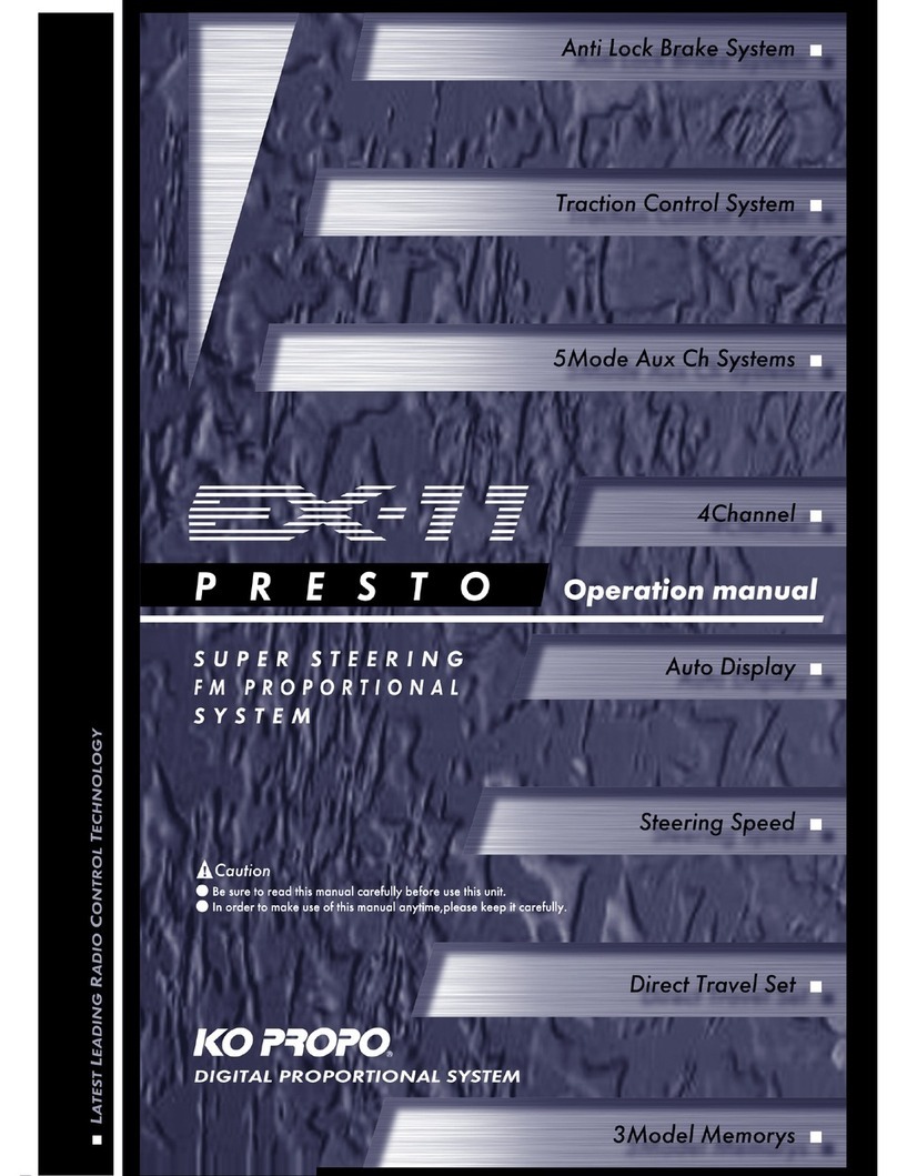
Ko Propo EX-11 Presto User manual

Ko Propo

Ko Propo EX-11 Presto User manual

Ko Propo EX-5UR User manual

Ko Propo

Ko Propo EX-5UR User manual

Ko Propo EX-1 ASF User manual

Ko Propo

Ko Propo EX-1 ASF User manual

Ko Propo EX-NEXT User manual

Ko Propo

Ko Propo EX-NEXT User manual

Ko Propo EX-10 EURUS User manual

Ko Propo

Ko Propo EX-10 EURUS User manual

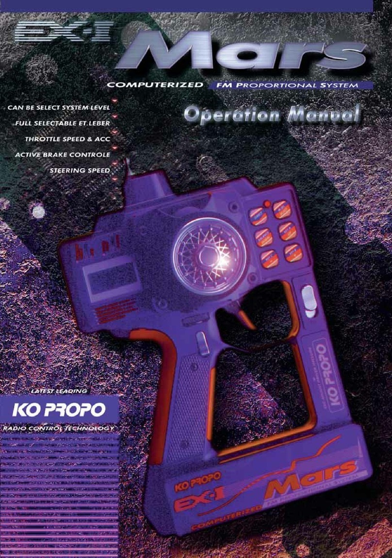
Ko Propo EX-1 Mars User manual

Ko Propo

Ko Propo EX-1 Mars User manual

Popular Transmitter manuals by other brands

Aeta Audio Systems SCOOP 3 5ASystem user manual

Aeta Audio Systems

Aeta Audio Systems SCOOP 3 5ASystem user manual

Velleman-Kit K6706B Illustrated assembly manual

Velleman-Kit

Velleman-Kit K6706B Illustrated assembly manual

Rokonet RWT71M433IQA manual

Rokonet

Rokonet RWT71M433IQA manual

Evikon E2660-CO-CO2 user manual

Evikon

Evikon E2660-CO-CO2 user manual

Kensington LiquidFM K33411US Instruction guide

Kensington

Kensington LiquidFM K33411US Instruction guide

Datexel DAT 1111 installation instructions

Datexel

Datexel DAT 1111 installation instructions

Zamel RNK-04 instruction manual

Zamel

Zamel RNK-04 instruction manual

Status SEM110 SERIES manual

Status

Status SEM110 SERIES manual

Emerson Rosemount 326P quick start guide

Emerson

Emerson Rosemount 326P quick start guide

Jamara CCX Pro Instruction

Jamara

Jamara CCX Pro Instruction

YOKOGAWA YTMX580 user manual

YOKOGAWA

YOKOGAWA YTMX580 user manual

NAPCO GEM-PIR manual

NAPCO

NAPCO GEM-PIR manual

ARTEX B406-4 Description, operation, installation and maintenance manual

ARTEX

ARTEX B406-4 Description, operation, installation and maintenance manual

evertz 7700 MultiFrame manual

evertz

evertz 7700 MultiFrame manual

Selve Commeo Control Operating	 instruction

Selve

Selve Commeo Control Operating instruction

AMP PST1 quick start guide

AMP

AMP PST1 quick start guide

rojaflex RHS1-W Original assembly and operating instructions

rojaflex

rojaflex RHS1-W Original assembly and operating instructions

Huato HE500 Series user guide

Huato

Huato HE500 Series user guide

manuals.online logo
manuals.online logoBrands
  • About & Mission
  • Contact us
  • Privacy Policy
  • Terms and Conditions

Copyright 2025 Manuals.Online. All Rights Reserved.