NILES ELECTRONICS NEU-4 User manual

NEU-4, -6, -8 AND -10
E-BEAM GUN
SWITCHING
POWER SUPPLY
INSTRUCTION MANUAL Version 3.00
NILES ELECTRONICS
Niles Electronics Inc.
440610 S. Grimmer Blvd.
Fremont, CA 94538-6382 USA
Tel.: (510) 252-0100
Fax: (510) 252-0106
Web Site: www.nileselectronics.com
Copyright Niles Electronics Inc. –All rights reserved
Feb. 2011

TABLE OF CONTENT
1
OVERVIEW.......................................................................................... 1-1
SYSTEM COMPONENTS...............................................................................1-1
LIST OF ACCESSORIES.................................................................................1-1
2
SPECIFICATIONS ............................................................................... 2-1
OVERALL SPECIFICATIONS.......................................................................2-1
OUTPUT FOR FILAMENT TRANSFORMER PRIMARY COIL.................2-1
DIMENTIONS AND WEIGHT .......................................................................2-2
3
INSTALLATION.................................................................................. 3-1
SAFETY PRECAUTIONS...............................................................................3-1
INTRODUCTION ............................................................................................3-1
RACK ASSWMBLY........................................................................................3-3
CABLE CONNECTIONS BETWEEN MODULES........................................3-7
FILAMENT TRANSFORMER CONNECTION.............................................3-7
HIGH VOLTAGE CABLE CONNECTION....................................................3-8
SYSTEM GROUNDING..................................................................................3-8
FILAMENT TRANSFORMER WIRING PHOTO..........................................3-9
POWER CORDS WIRING PHOTO...........................................................3-9
INTERLOCK CONNECTIONS.....................................................................3-10

2
HIGH VOLTAGE INTERLOCKS.................................................................3-11
AIR .................................................................................................................................3-11
VACUUM.........................................................................................................................3-11
TANK ..............................................................................................................................3-11
AUX 1 .............................................................................................................................3-11
EMISSION INTERLOCKS............................................................................3-11
FUSE ...............................................................................................................................3-12
HVAC..............................................................................................................................3-12
WATER ...........................................................................................................................3-12
AUX 2 .............................................................................................................................3-12
REMOTE CONTROL CONNECTIONS.......................................................3-13
D-SUB 37 REMOTE CONTROL SIGNAL LIST.........................................................3-13
REMOTE CONTROL CONNECTIONS -NEW...........................................3-15
RECOMMENDED REMOTE CONTROL CIRCUITRY..............................3-16
VOLTAGE-MATCHING AUTOTRANSFORMER……………………..3-18
4
POWER MODULE............................................................................... 4-1
SWITCHES:........................................................................................................................4-1
PILOT LIGHTS: ..................................................................................................................4-1
FUSE:................................................................................................................................4-1
5
HIGH VOLTAGE MODULE............................................................... 5-1
6
CONTROL MODULE.......................................................................... 6-1

3
FUNCTIONS....................................................................................................6-1
MAIN POWER: ...................................................................................................................6-1
HIGH VOLTAGE:................................................................................................................6-2
OUTPUT POWER &CONTROL SOURCE:.............................................................................6-3
EMISSION CURRENT:.........................................................................................................6-4
FILAMENT PRECONTION....................................................................................................6-5
FUSES IN THE BACK..........................................................................................................6-5
OPERATION OF THE CONTROL MODULE................................................6-6
PRELIMINARY PRECAUTIONS ............................................................................................6-6
INITIAL TURN ON..............................................................................................................6-6
TURN OFF .........................................................................................................................6-6
WARRANTY
SAFTY WARNING
USER RESPONSIBILITY
CONTACT
DISTRIBUTOR

1-1
1
OVERVIEW
SYSTEM COMPONENTS
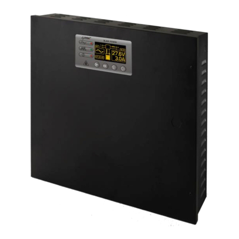
The Electron Beam (E-Beam) Gun Switching Power Supply is a direct current, regulated
constant high voltage power supply. It is produced only as a one-gun version. Intended for use
with E-Beam guns, it is compatible with E-Beam guns using electromagnetic deflection or
combinations of electromagnetic deflection and permanent magnet focusing.
The E-Beam Gun Power Supply consists of the following components:
Power Module with two power cords attached
High Voltage Module with a 15 ft HV coaxial cable attached
Control Module
Rack Assembly for Power and High Voltage Modules
A system of safety interlock functions protects both the operator and the equipment.
LIST OF ACCESSORIES
The following accessories will be included with the shipment of the Power Supply:
One filament transformer
One B+ connection cable
One 22″ 7-pin cable
One 66″ 7-pin cable
One 66″ ribbon cable **
One Instruction Manual (the one you are reading)
**Do not replace the ribbon cable with round computer cable nor with a longer cable. Doing so
will cause interference amongst conductors of the cable.

2-1
2
SPECIFICATIONS
OVERALL SPECIFICATIONS
Input Voltage for Control:
230 Volts, single phase, 50/60 Hz, 3 Amps
Input Voltage for Power:
400 Volts, 3-phase, 50/60 Hz
10 Amps for NEU-4, 15 Amps for NEU-6, 20 Amps for NEU-8
25 Amps for NEU-10
Maximum output power:
4 KW for the NEU-4 model
6 KW for the NEU-6 model
8 KW for the NEU-8 model
10 KW for the NEU-10 model
High voltage range:
from –3 kV to –10 kV (adjustable)
Maximum emission current:
0.4 Amps for NEU-4
0.6 Amps for NEU-6
0.8 Amps for NEU-8
1.0 Amps for NEU-10
Ripple:
less than 150 Volts p-p
OUTPUT FOR FILAMENT TRANSFORMER
PRIMARY COIL
Voltage: 0-230 Volts, single-phase, 50Hz or60 Hz
Primary Control: SCR pulse width control

2-2
Maximum Current: 2.0 Amps
Insulation rating for Filament Transformer (Secondary to Primary and Core): 20
KV DC minimum
DIMENSIONS AND WEIGHT
For NEU-4, NEU-6 and NEU-8
Control Module
Power Module
High Voltage Module
19″ wide (full rack)
half-rack wide
half-rack wide
3.5″ high (2U)
10.5″ high (6U)
10.5″ high (6U)
12.2″ case depth
18.5″ case depth
18.5″ case depth
15″ deep including
connectors and knobs
21" deep including parts
mounting on the case
21″ deep including parts
mounting on the case
10 lbs
40 lbs for NEU-4
41 lbs for NEU-6
40 lbs for NEU-8
39 lbs for NEU-4
40 lbs for NEU-6
42 lbs for NEU-8
For NEU-10
Control Module
Power Module
High Voltage Module
19″ wide (full rack)
half-rack wide
half-rack wide
3.5″ high (2U)
10.5″ high (6U)
10.5″ high (6U)
12.2″ case depth
20.5″ case depth
20.5″ case depth
15″ deep including
connectors and knobs
23" deep including parts
mounting on the case
23″ deep including parts
mounting on the case
10 lbs
42 lbs
45 lbs
The weights of the cables that connect between modules are not included.

3-1
3
INSTALLATION
SAFETY PRECAUTIONS
DANGER –HIGH VOLTAGE
High, potentially lethal, voltage is present within this equipment and at end of the
high voltage cable. Great care must always be exercised when working with this
equipment. Only qualified and properly trained personnel may test or work with
this equipment.
All connections must be made with the power cords unplugged from their sources,
or with the power turned OFF at the source (not just on the equipment). Work
should not be carried out in cramped and/or cluttered areas.
INTRODUCTION
The E-Beam Gun Power Supply is designed to be mounted in a standard 19-inch rack cabinet.
The complete installation comprises the following aspects:
Rack Assembly
Cable Connections Between Modules
Filament Transformer Connection
High Voltage Cable Connection
System Grounding
Interlock Connections
Remote Control Connections
Both the Power and the High Voltage Modules are half-rack wide and are to be mounted in the
rack assembly, which can be placed in a 19-inch rack. There should be ample clearance on both
the front and rear panels of these two modules to allow for proper airflow. If desired, it is

3-2
allowable to place these two modules in the lower part of the 19″ rack in order to preserve easier-
to-reach space for other modules. The cables connecting the Control Module and the High
Voltage Module are 66″ long to allow for such usage. However, separating these two Modules
by distances longer than 66″ will impair the Power Supply’s function. Only use the ribbon cable
supplied by Niles Electronics Inc. This cable carries both analogue and digital signals. Using
different type of cable may cause "crosstalk" among the conductors. The signal crosstalk can
impair or even permanently damage the power supply.

3-3
RACK ASSEMBLY
NOTE: All NE, NEU and NEDG series are using the same rack. Even though the pictures
may not show exactly the model you purchased, the assembly procedures are the same.
NOTE: Leaving the bolts slightly loose until all of the bolts are in position will make
minor adjustments easier to make. Drive all of the bolts tight with a 10 lb-in torque at the
end.
1. Place BRKT-P2 open side downwards
with FEX nuts facing forward. NOTE:
This piece looks very similar to BRKT-
P1. It is important not to confuse the two.
BRKT-P1 has notches in the front and the
back while BRKT-P2 doesn't.
2. Place BRKT-P3 open side downwards
directly behind BRKT-P2 so that the FEX
nuts are on the sides. NOTE: Orientation
of this piece is important. The front side
should be labeled. If there is no label, the
front is distinguished from the rear by the
following: On the sides, the distance
between the ends and the first FEX nut is
unequal in the front and the back. The
front side has a longer distance between
the edge and the FEX nut than the back side.
3. Looking at the assembly from the front,
line up the High Voltage Module on top of
BRKT-P2 and BRKT-P3 in the FRONT, LEFT
corner. The front panel of the HV Module
should hang over the two bottom pieces.
Back side has a
smaller distance.
Front side has a
larger gap.
Steps 1&2

3-4
4. Line up the two bottom holes in the front
panel to the holes in BRKT-P2. Screw in
two ½″ bolts with nylon washers, attaching
these two pieces together.
5. Place the Power Module to the right of the HV
Module so that it is lined up in the FRONT,
RIGHT corner of the two bottom pieces.
6. Line up the two bottom holes in the front panel of the Power Module to the holes
in BRKT-P2. Screw in two ½″ bolts with nylon washers, attaching these two
pieces together.
7. Place BRKT-P1 on top of the two Modules
directly behind the front panels with the FEX
nuts facing forward and the open side facing
downwards. The notches in this piece enable
the Modules to slide right out of the Rack
Assembly from the front without
disassembling the Rack. Line up the four
holes in the front panels with the four holes in
BRKT-P1 and screw in four ½″ bolts with
nylon washers.
BRKT-P1

3-5
8. Place BRKT-EAR-L to the left of the HV
module with the six FEX nuts lined up with the
holes in BRKT-P2 and BRKT-P3. The slanted
edge should be going downwards towards the
back, and the front flap should bend to the left
away from the modules. The back edge of
BRKT-EAR-L should be flush with the back of
BRKT-P2. If it is not, there is a gap between the two bottom pieces that bolts will
catch on when sliding out Modules from the Rack Assembly in the future.
9. Screw in six 3/8″ bolts with spring lock washers, affixing BRKT-EAR-L to
BRKT-P2 and BRKT-P3 (the two bottom pieces.)
10.Screw in two 3/8″ bolts with spring lock washers, affixing BRKT-EAR-L to
BRKT-P1 (the top piece.)
11.Place BRKT-EAR-R to the right of the power module. This should look
symmetrical to the left side, with the front flap bending to the right away from the
modules.
12.Screw in six 3/8″ bolts with spring lock washers, affixing BRKT-EAR-R to
BRKT-P2 and BRKT-P3 (the two bottom pieces.)
13.Screw in two 3/8″ bolts with spring lock washers, affixing BRKT-EAR-R to
BRKT-P1 (the top piece.)
The back edge of BRKT-
EAR-L should be flush
with BRKT-P2
The bottom piece should not stick out. To
fix this simply turn BRKT-P3 around.

3-6
The Completed Rack - 1
The Completed Rack - 2
Once assembled, the Rack Assembly will fit easily into a standard 19″ rack. It is designed with
the ease of Module removal in mind. To remove a Module, simply remove the four front bolts

3-7
and slide the Module out from the front of the Rack Assembly. Scratching along the bottom
pieces is part of normal wear.
We strongly suggest that a supporting bar or plate to be set up to support both the rear ends of
Power Module and HV Module.
CABLE CONNECTIONS BETWEEN MODULES
The connections are also labeled on the back panels of the Modules.
FILAMENT TRANSFORMER CONNECTION
Niles Electronics Inc. accommodates a filament transformer, since April 2005, with each
power supply. The filament resistance, at room temperature, should not be less than 5
mOhms (5 thousandth Ohms). Too low filament resistance will trigger the “fast-response
surge current sensor” circuitry. If the mentioned sensor is triggered, the fuse indicator
LED goes off while the fuse is intact. The user can reset the indicator LED by pushing
the “emission off” button. However, the problem cannot be solved until the filament

3-8
resistance is corrected or the short-circuit of filament block is resolved. Should any
customer have questions regarding this issue, please do not hesitate to contact Niles
Electronics Inc.
The core of the Filament Transformer must be connected to the Tank ground. It is advisable to
remove the paint/varnish from a small area around the mounting holes of the Transformer and
the frame. The mounting bolts themselves will establish a proper ground connection. As a result,
the Transformer Core and the Ground Shield will have the same potential as the Ground during
normal operation. The Filament Transformer Primary must be connected to the Output at the rear
panel of the Control Module. A 2.5 Amp Fuse is used for over current protection. Use of
AWG16 Wire is recommended for the Filament Transformer Primary Coil connections.
HIGH VOLTAGE CABLE CONNECTION
The High Voltage connection is made with RG 213/U Cable. Shipment of the E-Beam Gun
Power Supply will include a High Voltage Coaxial Cable in our standard length of
approximately 15 feet. The center conductor of this Coaxial Cable is the High Voltage Output
and should be connected to the Secondary Winding of the Filament Transformer. The Copper
Braided Shield should be connected to the Ground of the Vacuum Tank, as described in Filament
Transformer Connections (see the section above and photo below).
SYSTEM GROUNDING
Each of the four Modules has a Module Ground Stud. Connections should be made as follows:
1. Connect the Control Module Ground Stud to the High Voltage Module Ground stud.
2. Connect the High Voltage Module Ground Stud to the Power Module Ground Stud.
3. Connect the Power Module Ground Stud to the System Ground Stud.
4. Connect the Sweep Ground Stud to the Vacuum Tank Ground.
Warning: Even though this power supply can work well without grounding the cases mentioned
above, for the safety of the operating personnel, grounding must be done before operating the
power supply.

3-9
FILAMENT TRANSFORMER WIRING PHOTO
POWER CORDS WIRING PHOTO

3-10
INTERLOCK CONNECTIONS
The external interlocks are connected to the Power Supply and their installation is described
below.
WARNING
All statements pertaining to operator and equipment safety apply only if the
external interlocks are installed as specified below and only if the operator
does not disable the safety features, inherent in the interlocks, by bypassing
the switches. Although these interlocks are designed to protect both operator
and equipment, extra care and good judgment should always be exercised
when operating High Voltage equipment. It is conceivable that, under certain
circumstances, an interlock could fail and hence, the interlocks should never
be solely relied upon to provide 100% safety at all times.
D-SUB 15
CONNECTOR
PIN NO.
RIBBON CABLE
CONDUCTOR
NO.
SOURCE
INTERLOCK
HV
INTERLOCKS

3-11
HIGH VOLTAGE INTERLOCKS
The E-Beam Gun Power Supply has two groups of interlock connections: one for the High
Voltage and another for the Emission Current (Source Current). The High Voltage has the
following interlocks:
AIR
VACUUM
TANK
AUX 1
AIR:
Designed to detect when the equipment is overheating, both the Air Interlock light and the High
Voltage will shut off should the temperature become too high. This happens when there is not
sufficient fresh air in the system. In the event that this occurs, check the airflow of the High
Voltage Module. It is recommended, however, that the equipment not be turned off because the
system fan will drop the temperature of the equipment more rapidly. Pushing the HV “OFF”
button again will reset the Air Interlock switch automatically if the temperature has dropped
sufficiently. The light of the Air Interlock will come back on only if the reset has been
successful.
VACUUM:
A vacuum switch should be installed on the Tank so that it closes whenever there is enough
vacuum inside the Tank.
TANK:
When these interlocks are installed, the switches on the doors and high voltage panels will
normally remain open. They will be closed only when the doors of the chamber and all panels
are in place. These interlocks should be closed only when there is no possible chance of coming
into contact with high voltage.
AUX 1:
This interlock is provided to enable the user to insert additional interlocks, such as emergency off
pushbuttons, crucible rotation interlocks, etc. If more than one interlock is required, simply
connect the interlock switches in series.
EMISSION INTERLOCKS

3-12
The interlocks for the Emission Current are:
FUSE
HVAC
WATER
AUX 2
FUSE:
This fuse is in series with the Filament Transformer Primary Winding. If the Filament
Transformer is overloaded, the fuse will be burnt and its LED indicator will turn off. However, if
the LED indicator is off, the Fuse is not necessarily burnt as there is a Surge Current Sensor
Circuitry that can also turn off this LED indicator. Push the Source “OFF” button to turn the
LED indicator back on. After resetting, the emission can be turned back on by pushing the
Source “ON” button. However, if the both the Emission and the LED indicator are off again,
there must be a problem that needs attention. At such point, check the Fuse first. Before
replacing the fuse, find out the cause of burning the Fuse. If the fuse is not burnt, it could result
from the Secondary Winding being in short circuitry that causes the Surge Current Sensor
Circuitry to act. An inspection of the Filament Transformer and/or the Filament circuitry is
required before operations can be resumed.
Warning: Even though the Filament Driver Circuitry is protected, repeatedly trying to turn on
emission without removing the cause of the failure may permanently damage the Filament
Driver Circuitry.
HVAC:
The purpose of this interlock is to ensure that sufficient vacuum is present inside the Tank before
the source can be energized. Normally, this level of vacuum is the same for the level required to
energize the vacuum gauge filaments.
WATER:
A water flow switch should be installed in the return line of the cooling system for the E-BEAM
GUN. This switch should close automatically once there is sufficient water flow to cool the Gun
and associated shields.
AUX 2:
This interlock is provided to enable the user to insert additional interlocks. If more than one
interlock is required, simply connect the interlock switches in series.

3-13
REMOTE CONTROL CONNECTIONS
D-SUB 37 REMOTE CONTROL SIGNAL LIST
(CAN BE DIVIDED INTO TWO 15 CONDUCTOR RIBBON CABLES AND
CONNECTED TO TWO D-SUB 15 CONNECTORS)
* This voltage is mainly for remote control use. It can supply enough current for the
recommended remote control circuitry. Do not use this voltage for other purposes.
** The High Voltage is turned on by the Low-to-High edge of the
ON/OFF Control Signal. 5V is enough for the High State, but do
not input more than 12V. During the time that the ON/OFF Control
Signal stays high, the front panel ON/OFF push buttons also gain control of the ON/OFF
operation for safety reasons. The High Voltage is turned off by the Low State of its ON/OFF
Control Signal. During the time that this Signal stays low, the front panel “ON” button cannot
turn on the High Voltage. These statements are also true of the Emission Current.
HAND HELD PLC FUNCTION DESCRIPTION
1 1 21 11 Ground for Digital Signals
220 22 30 OUT Is this remote controlactivated? H=YES L=NO
3 2 23 12 OUT Are all HV Interlocks OK? H=YES L=NO
421 24 31 OUT Are all Emission Current Interlocks OK? H=YES L=NO
5 3 25 13 IN HV ON/OFF Control Signal **
622 26 32 IN Emission Current ON/OFF Control **
7 4 27 14 OUT Analog Control Reference Voltage VREF = 5.3 ~ 5.6V *
823 28 33 IN Non-Inverting Input for HV *** ^
9 5 29 15 IN Inverting Input for HV *** ^
10 24 30 34 IN Non-Inverting Input for Emission Current ***
11 631 16 IN Inverting Input for Emission Current ***
12 25 32 35 Ground for Analog Signals
13 733 17 OUT HV Reading +5V represents 10KV
14 26 34 36 OUT Emission Current Reading –3V Represents 600mA
15 835 18 IN GND-Ribbon Cable in use. OPEN-No Connection ****
16 27 36 37 NOT USED
17 937 19 NOT USED
18 28 NOT USED
19 10 NOT USED
20 29 NOT USED
D-SUB 37
Pin No.
Ribbon
Cable
Conductor
No.
(Digital High = +12V Digital Low = 0V)
All output signals have 1 KWResistor in series
D-Sub 37
Pin No.
Signal
Direction
Ribbon
Cable
Conductor
No.
This manual suits for next models
3
Table of contents

