Nippon RA-4300FG+ User manual

RA-4300FG+
Service Manual
Document
Number NIC-704-2033-01
Date of
Issue 2020/2/26
Control
Department
Technical Service
Group Page 1/48
RA-4300FG+
Service Manual
Nippon Instruments Corporation
Technical Service Group
Date Prepared Checked Approved
First
Edition
2020/2/26 Kinoshita - Noda

NIC-704-2023-01
Reducing-Vaporization Mercury Analyzer
Mercury/RA-4300FG+ Service Manual
Table of Contents
INTRODUCTION ................................................................................................................ 1
SAFETY PRECAUTIONS ............................................................................................... 1
Meaning and explanation of symbols............................................................... 1
Precautions for work......................................................................................... 1
TARGET USERS.......................................................................................................... 1
UPDATING THE FIRMWARE ............................................................................................ 2
METHOD OF UPDATING THE FIRMWARE........................................................................ 2
Loading the file ................................................................................................. 3
Writing............................................................................................................... 4
Enabling the change......................................................................................... 5
IF THE FIRMWARE UPDATE FAILS.................................................................................. 6
REPLACING PARTS.......................................................................................................... 7
REPLACING THE MAIN BOARD...................................................................................... 7
REPLACING THE REAGENT PUMP................................................................................. 8
REPLACING THE MEASURING CAP AND BUBBLER .........................................................11
REPLACING THE REACTION TUBE .............................................................................. 13
REPLACING THE REAGENT TUBE ............................................................................... 16
REPLACING THE LAMP .............................................................................................. 19
REPLACING THE MERCURY COLLECTOR TUBE ............................................................ 23
REPLACING THE HEATER AND THERMOCOUPLE FOR COLLECTOR TUBE........................ 24
REPLACING THE ZERO-GAS FILTERS.......................................................................... 26
REPLACING THE NAFION TUBE.................................................................................. 27
REPLACING THE NEEDLE VALVE................................................................................. 27
REPLACING THE V1 VALVE........................................................................................ 28
REPLACING THE FLOW RATE SENSOR........................................................................ 29
REPLACING THE MASS FLOW CONTROLLER................................................................ 30

Table of Contents
NIC-704-2023-01
REPLACING THE DISPENSER ARM ASSEMBLY.............................................................. 31
REPLACING THE ACTIVE CARBON FILTER FOR THE COVER........................................... 36
ADJUSTMENTS............................................................................................................... 38
CLEANING THE CELL................................................................................................. 38
ADJUSTING THE OFFSET OF THE DISPENSER ARM AND TURNTABLE ............................. 40
ADJUSTING THE BELT OF THE TURNTABLE.................................................................. 41
MAINTENANCE ............................................................................................................... 43
DAILY INSPECTION............................................................................................................... 43
CORRECTIVE MEASURES............................................................................................. 44
ABNORMAL BLANK VALUE.......................................................................................... 44
WASHING METHOD................................................................................................... 45
Washing the reagent tube .............................................................................. 45
Washing the cap and bubbler......................................................................... 45
POOR SENSITIVITY ................................................................................................... 45
Recovering from poor sensitivity.................................................................... 46
Checking for and recovering from leakage .................................................... 46
OTHER TOPICS............................................................................................................... 47
PROVIDING THE PROTECTION FOR RELOCATION OR TRANSPORTATION........................ 47
PRECAUTIONS FOR DISPOSING OF THE ANALYZER...................................................... 47
CONTACT......................................................................................................................... 48
Introduction
1
NIC-704-2023-01
Introduction
Safety precautions
Meaning and explanation of symbols
Indicates that incorrect handling could result in the death or severe
injury to the operator.
Indicates that incorrect handling could result in
minor injury or
moderate injury to the operator or damage to property.
Precautions for work
• When removing the cover of the analyzer, be sure to cut off the power supply in
advance. Otherwise, an electric shock or machine damage may occur.
• Before updating the firmware, confirm that the version of the software on the PC is
compatible with the firmware.
• Remove any chemicals (e.g. in sample bottles and regent bottles) from the turntable
of the analyzer because they may accidentally spill during work.
Target users
Only qualified users, who have completed the service work training program in Nippon
Instruments Corporation, are allowed to conduct the work described in this work manual.
Observe the safety precautions to conduct work.
Warning
Caution
Warning
Caution
Service Manual
2
Updating the firmware
•Before updating the firmware, confirm that the version of the software on the PC is
compatible with the firmware.
Method of updating the firmware
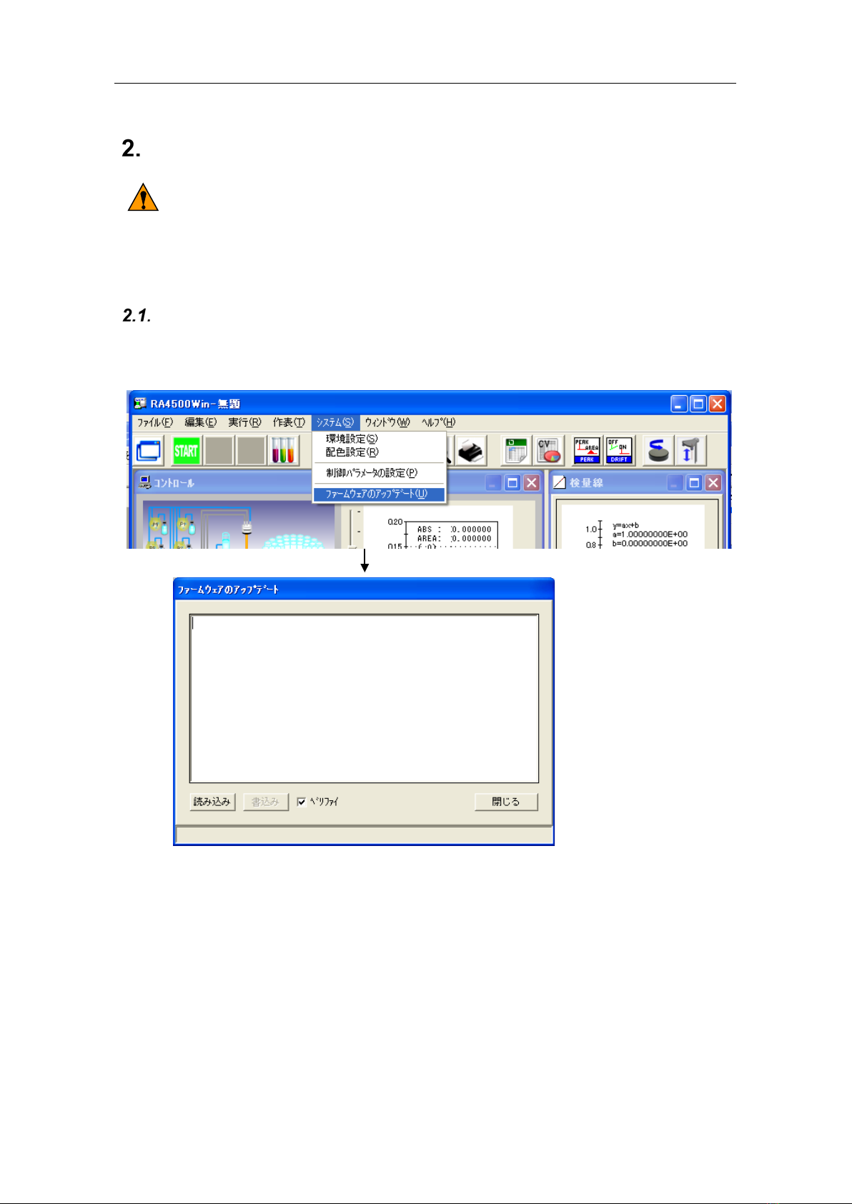
Because the firmware update function is built into both RA4Win and the firmware, you can
easily update the firmware. From the System menu bar of RA-4win, click [Update firmware].
The above window appears. You can update the firmware in this window.
The following is the flow of the updating procedure:
Load the firmware file into the PC.
Write the loaded data into the flash memory of the RA4’s main board.
Turn off the power of the main unit and then turn it on again to enable the change.
Warning
Service Manual
3
Loading the file
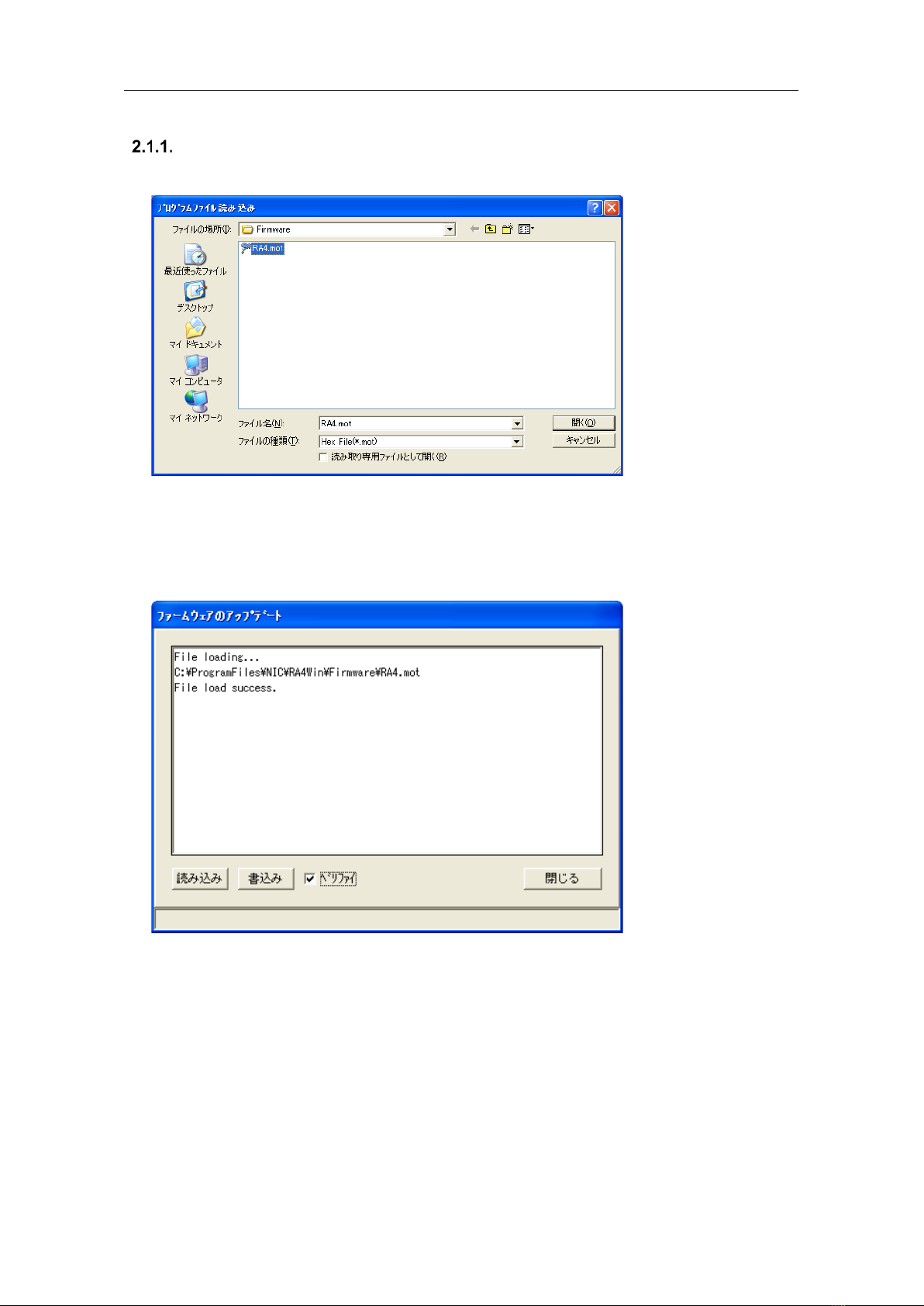
Click [Load] button to load the firmware file. The file name is normally “RA4.mot.”
When the loading is successfully completed, the message “File load success” appears as
shown below, and [Write] button becomes clickable. If there is something wrong with the
loaded file, the message “File loading fail” appears, and [Write] button stays grayed out.

Service Manual
4
Writing
Click [Write] button to write the loaded data into the flash memory of the RA4’s main unit.
The sequence of the writing process is erasing, programming (writing), and verifying.
* Do not turn off the power during the writing process, otherwise you will not be able
to rewrite the firmware.
You can skip the verification step by deselecting [Verify] checkbox even during the process.
[Writing window]
[Verifying window]

Service Manual
5
Enabling the change
When the writing is complete, the following window appears. Click [OK] to exit the program.
Turn off the power of the RA4’s main unit, and then turn it on again.
The update is enabled after rebooting.

Service Manual
6
If the firmware update fails
If you turn off the power during the update of the firmware, the program cannot be written
normally. In such a case, you cannot even start up the system by turning on the power
again. Because the system cannot start up, you cannot rewrite the program through the
normal method.
If you are in this situation, you need to write the firmware by starting up the system in boot
mode, a mode dedicated to updating the firmware.
Turn off the power, open the rear cover of the main unit, and set SW1 on the CPU board
to the positions of boot mode.
Confirm that the PC and the RA4’s main unit are connected via ethernet cables. Then
turn on the power.
Start RA4Win.
Write the firmware using the procedure in 2.1. Method of updating the firmware.
When the writing is complete, turn off the power, set SW1 on the CPU board back to
the positions of normal mode, and then turn it on again. The procedure is now
complete.
Boot mode
Boot mode
Normal mode
Normal mode
Service Manual
7
Replacing parts
• When removing the cover of the analyzer, be sure to cut off the power supply in
advance. Otherwise, an electric shock or machine damage may occur.
• Remove any chemicals (e.g. in sample bottles and regent bottles) from the turntable
of the analyzer because they may accidentally spill during work.
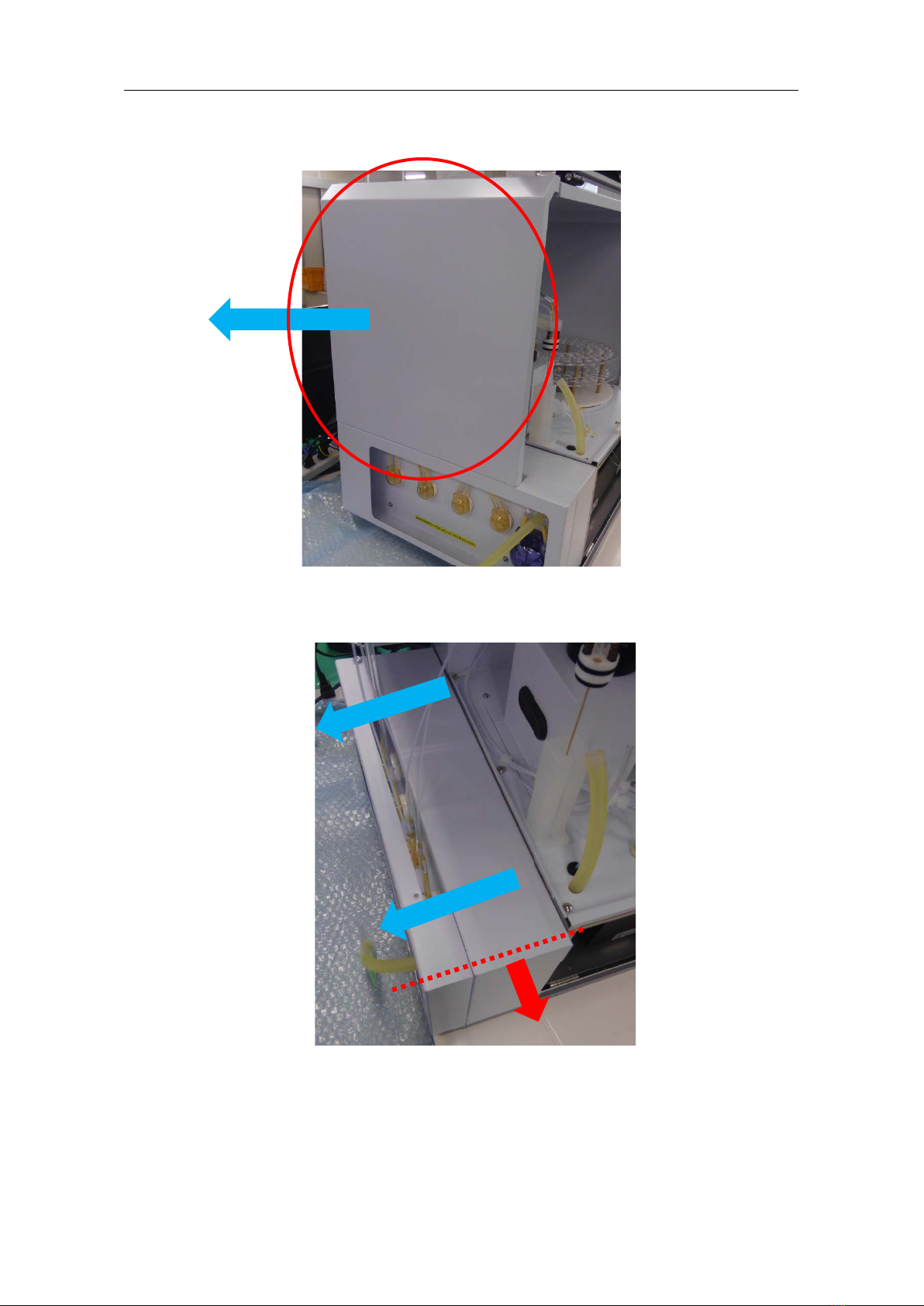
Replacing the main board
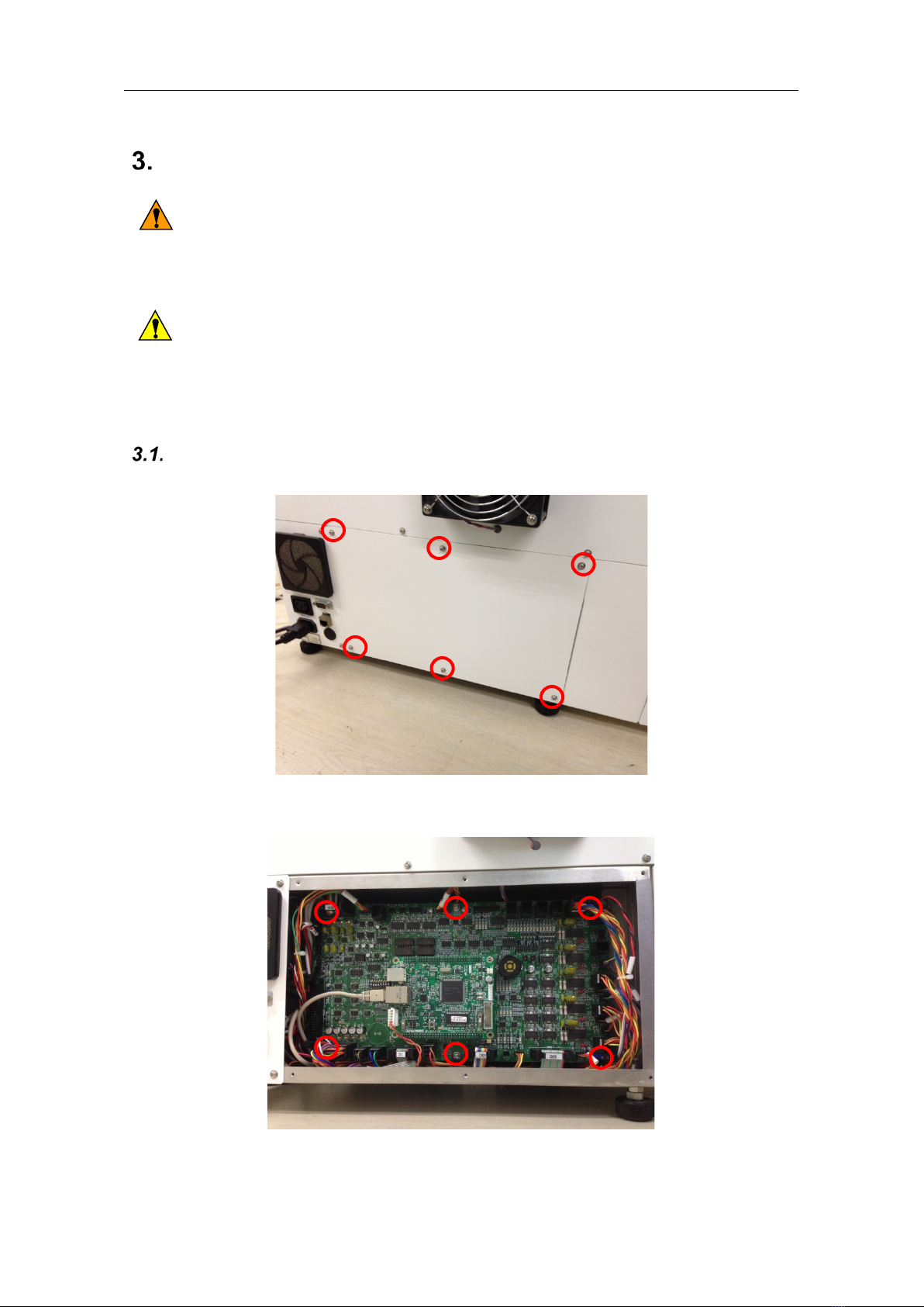
Remove the six screws from the rear side of the analyzer.
Disconnect the connectors from the main board, and remove the six screws.
Install a new main board by reversing the disassembling procedure.
Warning
Caution
Service Manual
8
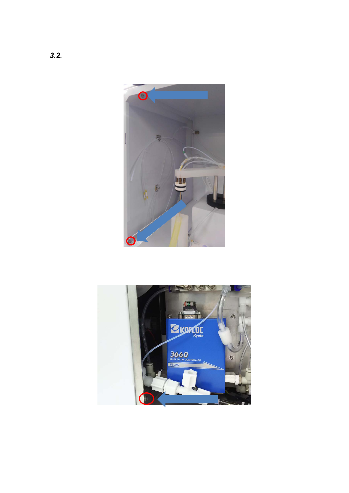
Replacing the reagent pump
Remove the two screws from the side plate so that you can remove the pump mounting
base.
Remove the screw from the pump mounting base.
Service Manual
9
Slide the left-side plate toward the back and remove the plate.
Slide the pump mounting base toward you, and then move it to the left and detach the
base.
Service Manual
10
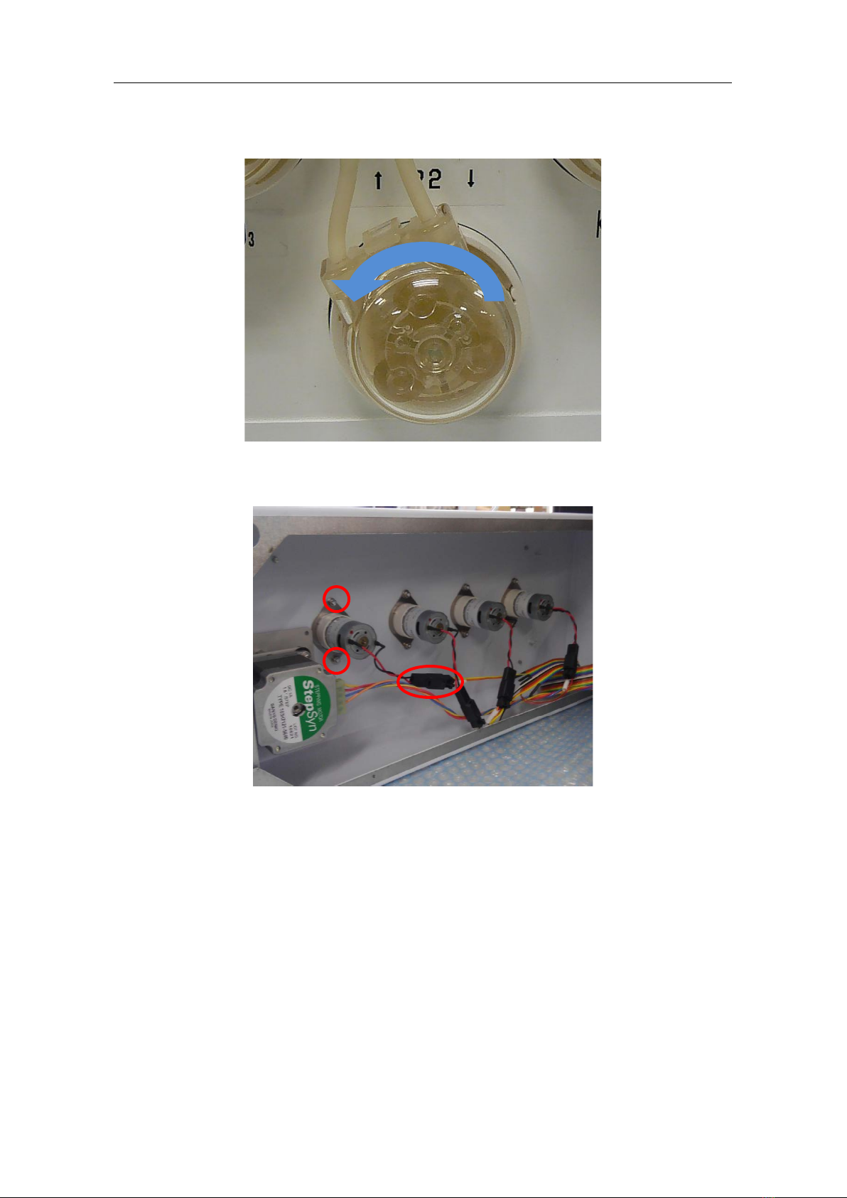
Turn thehead of the reagent pump to be replaced counterclockwise,and detach the head.
From the inside of the pump mounting base, remove the nuts holding the pump, and
disconnect its connector. Then replace the pump.
After installing a new reagent pump, reassemble the parts using the reverse procedure.

Service Manual
11
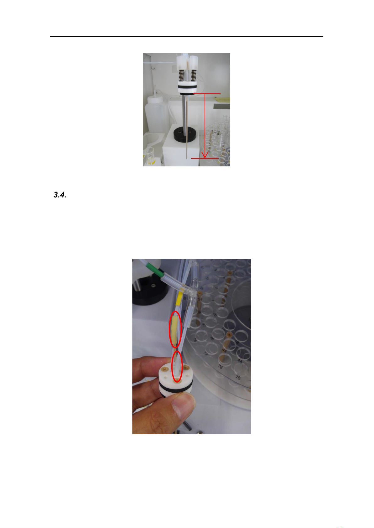
Replacing the measuring cap and bubbler
OntheMaintenancescreenofthemeasuringsoftware,movethemeasuringcapposition,
and then turn off the power of the analyzer. * Set the ARM to [2: B STAGE], and then set
the LIFT to [6: MEASURE].
Unscrew the three screws holding the cap, and then remove the cap.
Detach the reagent tube, reaction tube, and bubbler from the removed cap.
Assemble the cap.
* Pass the bubbler through the cap rubber in advance.
* Do not tighten the screws too much. If the rubber is crushed, the insertion of a tube will
become difficult.
* Adjust the protrusion of the bubbler to 114 mm from the top of the cap gasket.

Service Manual
12
Reassemble the parts using the reverse procedure. Slide the spring over each resin
screw, and tighten the screws with a screwdriver until the screws do not turn anymore.
* If you tighten the screws too much, you may damage them.
* If the bubbler is leaning, you can correct it by loosening the screws.
Confirm that the protrusion of the bubbler is 114 mm from the top of the cap gasket.
* Excessively tightening the countersunk head screw of the cap makes it difficult to adjust
the protrusion of the bubbler.
114 mm
Service Manual
13
Replacing the reaction tube
Referring to [3.3. Replacing the measuring cap and bubbler], unscrew the three screws
holding the cap, and then remove the cap.
Pull the old reaction tubes out of the cap.
Connect the yellow-marked tube to the bubbler.
In addition, insert the transparent tube into the cap hole closer to you.
114 mm
Service Manual
14
Referring to [3.3. Replacing the measuring cap and bubbler - Step ], fix the cap in
place using the reverse procedure.
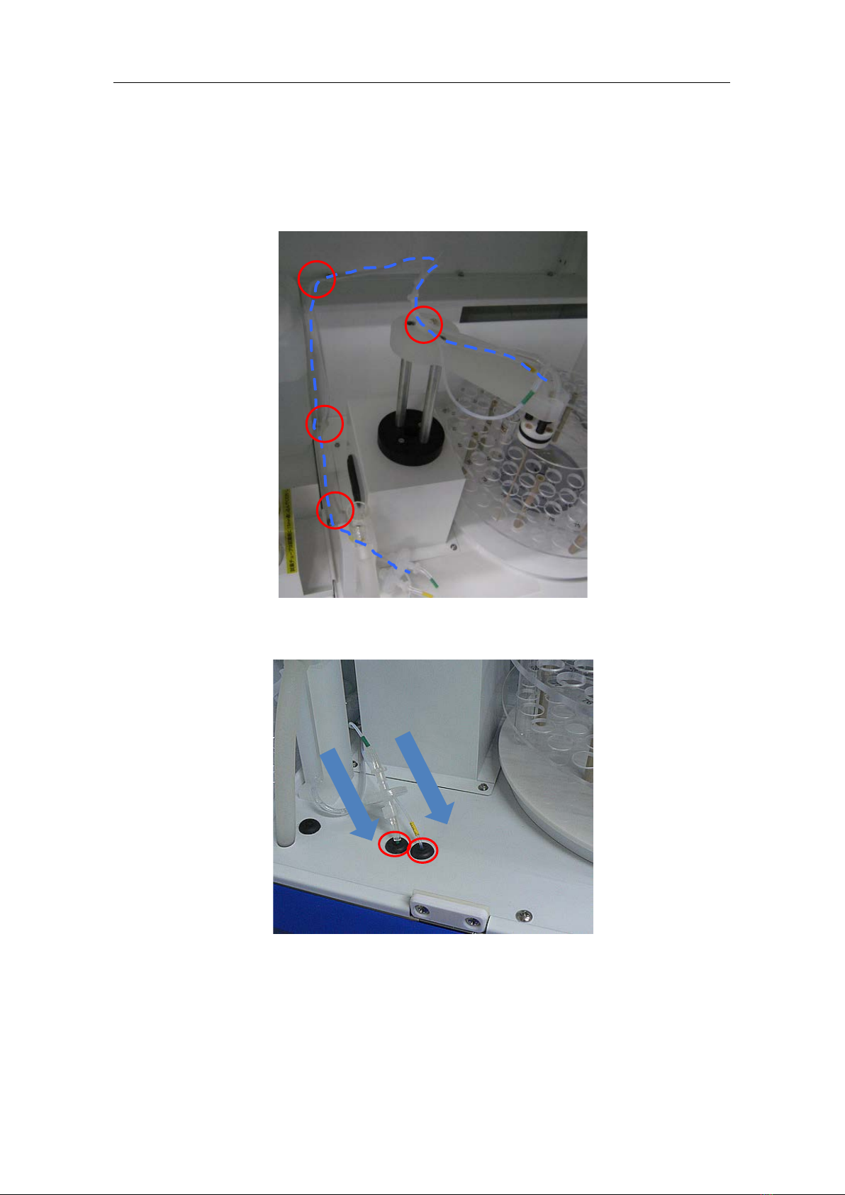
Run the tube along the route as shown in the picture below.
Hook the tube onto the clamps circled in the picture below.
Insert the yellow-marked tube into the grommet on the right side, and insert the green-
marked tube into the grommet on the left side.

Service Manual
15
Connect the yellow-marked tube to the check valve, and connect the green-marked tube
to the Teflon joint.
After the completion of assembling, conduct the procedure for checking the verticality of
the bubbler on the Maintenance screen. Place a sample bottle in No.1 holder, and then
set the [Bubbler Side] to “1” on the Maintenance screen. The measuring cap will move to
No.1 holder.
Check the verticality of the bubbler. If the bubbler is leaning, adjust it by loosening the
screws so that the cap becomes horizontal. However, to prevent the cap from coming off,
tighten at least one screw until it does not turn anymore.

Service Manual
16
Replacing the reagent tube
Referring to [3.3. Replacing the measuring cap and bubbler], remove the cap.
* Before starting this work, discharge any reagent from the tube by executing [Reagent
Discharge].
Unscrew the screws from the measuring cap. Then pull the old reagent tubes (P1, P2,
and P4) out of the cap.
Connect new reagent tubes (P1, P2, and P4) to the measuring cap.
Insert the reagent tubes into the two holes on the far side of the cap. In addition, slide the
heat-shrinkable tube over the bubbler and reagent tubes.
46 mm
10 mm
Heat-shrinkable
tube

Service Manual
17
Run the tube along the dashed line as shown in the picture below.
Pass the tube through the guides at the three spots.
Connect the reagent tube to the pump tube.
Insert the tube firmly so that the tube will not come off. (15 mm as a guide)
* If it is difficult to insert the tube, apply some alcohol to the tube to make it easier.
* To make the connection work easier, insert the tube before locking the pump head to
the motor unit rather than insert the tube after locking the pump head to the motor unit.
Table of contents
Other Nippon Laboratory Equipment manuals


Popular Laboratory Equipment manuals by other brands


Mecmesin
Mecmesin Vortex-dV operating manual

Agilent Technologies
Agilent Technologies Labware MiniHub quick guide

Sorvall
Sorvall MT-2B ULTRAMICROTOME operating instructions

ANDO Technik
ANDO Technik DOSATRON D8R owner's manual

FINO
FINO FINODOSIL User information

Waters
Waters Xevo TQD IVD Overview and maintenance guide