Sorvall MT-2B ULTRAMICROTOME User manual
s
Du
Pont
Company
I I
T·2
ULTRAMICROTOME
Clinical
and
Instrument
Systems
Division
SorvaJI®
Products
Wilmington, Delaware 19898
U.S.A.
Sorvall®
Microtomes
PN
16153-2
Issued
March
1984

ii
Sorvall®
Instruments
This
manual
is a guide for
the
use
of
the
SORVALL®
MT-2B
ULTRAMICROTOME
e
Data
herein
has
been
verified
and
validated
and is
believed
adequate
for
the
intended
use
of
the
instrument.
If
the
instrument
or
procedures
are
used
for
purposes
over
and
above
the
capabilities
specified
herein,
confirmation
of
their
validity
and
suitability
should
be
obtained;
otherwise,
DuPont
does
not
guarantee
results
and
assumes
no
obligation
or
liability.
This
publication
is
not
a
license
to
operate
under,
nor a
recommendation
to
infringe
upon, any
process
patents.
e
Publications
prior
to
the
Issue
Date
of
this
manual
may
contain
data
in
apparent
conflict
with
that
provided
herein.
Please
consider
all
data
in
this
manual
to
be
the
most
current.
NOTES, CAUTIONS,
and
WARNINGS
within
the
text
of
this
manual
are
used
to
emphasize
important
and
critical
instructions.
IWARNING I
!cAUTION~
NOTE
An
operating
procedure
which,
if
not
correctly
followed,
could
result
in
personal
injury,
affect
the
operator's
health,
or
contaminate
the
environment.
An
operating
procedure
which,
if
not
strictly
followed,
could
result
in
damage
of
equipment.
Highlights
essential
information.
Sorvall®Instruments
Table
of
Contents
Paragraph
1-l.
l-2.
l-3.
l-4.
2-l.
2-2.
2-3.
2-4.
2-5.
2-6.
4-l.
4-2.
4-3.
4-4.
4-5.
4-6.
4-7.
5-l.
5-2.
5-3.
5-4.
5-5.
5-6.
5-7.
TABLE
OF
CONTENTS
WARRANTY.
Section
1.
DESCRIPTION
SCOPE
OF
THE
MANUAL . . .
DESCRIPTION
OF
THE MT-2B .
SPECIF!CA
TIONS • • • •
PARTS
AND
ACCESSORIES
.•
Section
2.
INSTALLATION
INSPECT!O
N • • . . . . • • •
LOCATION
• • . . • • • • • . • • • •
ASSEMBLY • . • • • • . • . • • • • .
ELECTRICAL
REQUIREMENTS
..•••.
MOVING THE MT-2B
ULTRAMICROTOME
•
CONTAMINATION
• • • • • • . • • • .
Section 3. MT-2B PARTS, CONTROLS & INDICATORS
Section
4.
OPERATION
SPECIMEN
PREPARATION
••..•••••••.•.••
SPECIMEN
AND
KNIFE POSITIONING • • • • • • • • . . •
SPECIMEN
AND
SPECIMEN
HOLDER
INSTALLATION
••••
KNIFE
INSTALLATION
AND
KNIFE
HOLDER
ADJUSTMENT
•
TRIMMING.
• • • • • • • • • • •
SECTIONING • • • • • • • • • • •
SERIAL
THIN
AND
THICK
SECTIONS
• • • • • •
Section
5.
MAINTENANCE
PARTS
REPLACEMENT
•.•
INSPECTION
AND
CLEANING
COVER
REMOVAL
••
LUBRICATION
.••••••
LAMP
REPLACEMENT
• • •
FUSE
REPLACEMENT
• • •
TROUBLESHOOTING
SECTIONING
DIFFICULTIES
Page
• v
1-l
1-l
1-1
l-2
. 2-1
• 2-1
•
2-l
•
2-2
•
2-2
• 2-2
• 4-1
.
4-l
•
4-2
•
4-3
•
4-5
•
4-9
• 4-10
.
5-l
.
5-l
.
5-l
•
5-3
.
5-3
•
5-4
•
5-4
iii
Table
of
Contents
iv
Figure
l-1.
3-1.
3-2.
3-3.
4-l.
4-2.
4-3.
4-4.
4-5.
5-l.
Table
l-l.
l-2.
3-1.
3-2.
3-3.
4-l.
5-l.
LIST
OF
ILLUSTRATIONS
Sorvall® MT-2B
tntramicrotome
MT-2B
Parts
Identification·
·
Knife
Stage
Parts
. . . . .
Controls
and
Indicators
. . .
Specimen
Holder
Installation
.
Glass
Knife
Dimensions
. . .
Adjusting
Glass
Knife
Height.
Ribbon
Formation
. . . . .
Diagram
of
Precision
Trimming
Sequence
Rear
View
of
MT-2B
(Rear
Cover
Removed)
LIST
OF
TABLES
Parts
and
Accessories
Supplied
. • • . •
Additional
Parts
and
Accessories
• • • .
MT-2B
Parts
Identification
and
Function
•
Function
of
the
Knife
Stage
Parts
. . . •
Controls
and
Indica
tors
• . . . • • • .
Summary
of
Precision
Trimming
Sequence
Troubleshooting
Chart
-Sectioning
Difficulties
Sorvall®Instruments
Page
vi
3-2
3-4
3-6
4-2
4-3
4-4
4-6
4-7
5-2
Page
l-2
l-3
3-l
3-3
3-5
4-8
5-4
Warranty
WARRANTY
The
Sorvall® MT-2B
Ultramicrotome
is
warranted
to
be
free
from
defects
in
materials
and
workmanship
for a
period
of
one
year
from
the
date
of
delivery.
DuPont
will
repair
or
replace
and
return
free
of
charge
any
part
which is
returned
to
its
factory
within
said
period,
transportation
prepaid
by
user,
and
which is found upon
inspection
to
have
been
defective
in
materials
or
workmanship. This
warranty
does
not
include
normal
wear
from
use,
it
does
not
apply
to
any
instrument
or
part
which
has
been
altered
by
anyone
other
than
an
employee
of
DuPont,
nor
to
any
instrument
which
has
been
damaged
through
accident,
negligence,
failure
to
follow
operating
instructions,
the
use
of
electric
currents
or
circuits
other
than
those
specified
on
the
plate
affixed
to
the
instrument,
use
beyond
the
specified
capacity
of
the
instrument,
misuse
or
abuse.
DuPont
reserves
the
right
to
change,
alter,
modify or
improve
any
of
its
instruments
without
any
ol;>ligation
whatever
to
make
corresponding
changes
to
any
instrument
previously
sold
or
shipped.
THE
FOREGOING
OBLIGATIONS
ARE
IN
LIEU
OF
ALL
OTHER
OBLIGATIONS
AND
LIABILITIES INCLUDING
NEGLIGENCE
AND
ALL
WARRANTIES
OF
MERCHANTABILITY
OR
OTHERWISE,
EXPRESSED
OR
IMPLIED
IN
FACT
OR
BY
LAW,
AND
STATE
OUR
ENTIRE
AND
EXCLUSIVE LIABILITY
AND
BUYER'S
EXCLUSIVE
REMEDY
FOR
ANY CLAIM
OR
DAMAGES IN
CONNECTION
WITH
THE
SALE
OR
FURNISHING
OF
GOODS
OR
PARTS,
THEIR
DESIGN, SUITABILITY
FOR
USE,
INSTALLATION
OR
OPERATION.
DUPONT
WILL
IN
NO EVENT BE LIABLE
FOR
ANY
SPECIAL
OR
CONSEQUENTIAL
DAMAGES WHATSOEVER,
AND
OUR
LIABILITY
UNDER
NO
CIRCUMSTANCES
WILL
EXCEED
THE
CONTRACT
PRICE
FOR
THE
GOODS
FOR
WHICH LIABILITY IS
CLAIMED.
v

Sorvall®Instruments
Figure
1-1.
Sorva/1®
MT-28
Ultramicrotome
vi

Sorvall®
Instruments
Description
Section
1.
DESCRIPTION
1-1.
SCOPE
OF
THE MANUAL
This manual provides you with
the
information
you will
need
to
install,
operate
and
maintain
your MT-2B
Ultramicrotome.
If
you
encounter
any problem
concerning
either
operation
or
maintenance
that
is
not
covered
in
this
manual,
please
contact
the
nearest
district
office
or
local
representative
of
DuPont's
Clinical
and
Instrument
Systems
Division, Sorvall®Products,
listed
on
the
back
of this
manual.
1-2. DESCRIPTION
OF
THE MT-2B
The Sorvall MT-2B
Ultramicrotome
is used
to
produce
ultrathin
sections
of
specimens
for
light
or
electron
microscopy. The
microtome
is
capable
of
cutting
sections
in
the
range
of
10
nm
to
4)lm.
Specimen and Knife Positioning
The MT-2B
cantilever
arm
advances
the
specimen
a maximum
of
85
)1m
at
a 50 nm
setting.
Total
advance
can
be
as much
as
!50
]1m
at
the
4
]1m
setting.
The
specimen
holder
that
is supplied with
the
microtome
permits
specimen
orientation
in
different
planes
around
the
knife edge by allowing
360°
rotation
of
the
specimen
holder
as
well
as
a
20°
arc
above and below
the
central
axis.
The
microtome
knife
stage
assembly
rotates
about
the
vertical
axis
that
passes through
the
specimen/knife
contact
point. The
knife
stage
assembly
rotates
30°
to
the
left
and
right
and can
be
locked
into
any position in
this
60°
range.
The knife
stage
assembly
also
provides
coarse
and fine
front
to
back
adjustment.
Specimen Viewing
The MT-2B is equipped with a
variable
stereozoom
microscope which
can
be
moved
forward
and
back.
A
built-in
fluorescent
lamp
provides wide
angle
illumination.
Cutting
The MT-2B
can
either
be
used manually or
automatically
by using
the
motor
drive.
The
duration
control
determines
the
length
of
the
stroke
at
the
preset
cutting
speed.
1-3. SPECIFICATIONS
,.
Depth.
'"
Width .
e Height
e Mass (Weight)
e
Electrical
Requirements*
56 em (22 in)
27
em
(10-3/4
in)
47 em
(!8-l/2
in)
to
top of
stereomicroscope
54.5
kg (120 lbs)
ll5V,
60
Hz
.,_
For
220V,
50 Hz operation, Cat. No.
04264
step--down
transformer
is
required.
1-1

Description
Sorvall®Instruments
1-2
o
Control
Specifications
Manual
Mechanical
Stage
Advance:
Coarse
advance
. .
Fine
advance
. . .
Automatic
Advance:
Variable
. . . •
Limit
of
advance
Cutting
Speed:
20
mm
100 flm
l 0 nm
to
4
flm
85
fJm
at
50
nm
per
section
150
flm
at
4
flm
per
section
Variable
between
0.09
mm/s
to
3.2
mm/s
in
motor
driven
mode;
manual
mode
speed
variable
by
handwheel
revolutions.
Sectioning
Rate:
Duration
Control
• . . .
Range
(at
2 mm
duration
setting)
• . . . . • . .
Knife
Adjustment:
Longitudinal
. .
Lateral
• . . •
Specimen
Orientation:
Around
central
axis .
Vertical
from
central
axis
Knife
stage
rotation.
. .
2 mm
to
10
mm
4
sections/min
at
speed
0.1
mm/s
to
15
sections/min
at
speed
3.0 m
m/s
20 mm
12
mm
1-4.
PARTS
AND
ACCESSORIES
The
parts
and
accessories
supplied
with
the
basic
MT-2B
Ultramicrotome,
(Cat.
No.
16188)
are
listed
in
Table
l-1.
Catalog
Number
16190
16193
16189
16913
16916
16815
16915
61055
16800
16841
16153
Table 1-1.
Parts
and
Accessories
Supplied
Description
Microscope
Arm
Assembly
Variable
Stereomicroscope
Accessory
Pack
containing:
Base
Plate
Assembly
Microscope
Stand
Assembly
Plastic
Shield
Microscope
Holder
Assembly
Cap
Screws
(3
ea)
Dust
Cover
Accessory
Box
containing:
(Fluorescent
Bulb,
Starter,
Vials,
Fuses,
Bearing
Oil,
Screwdriver,
Knife
Height
Adjusting
Wrench,
Lubricating
Grease,
Vise-Type
Holder)
Instruction
Manual
Son·all®
Instruments
Description
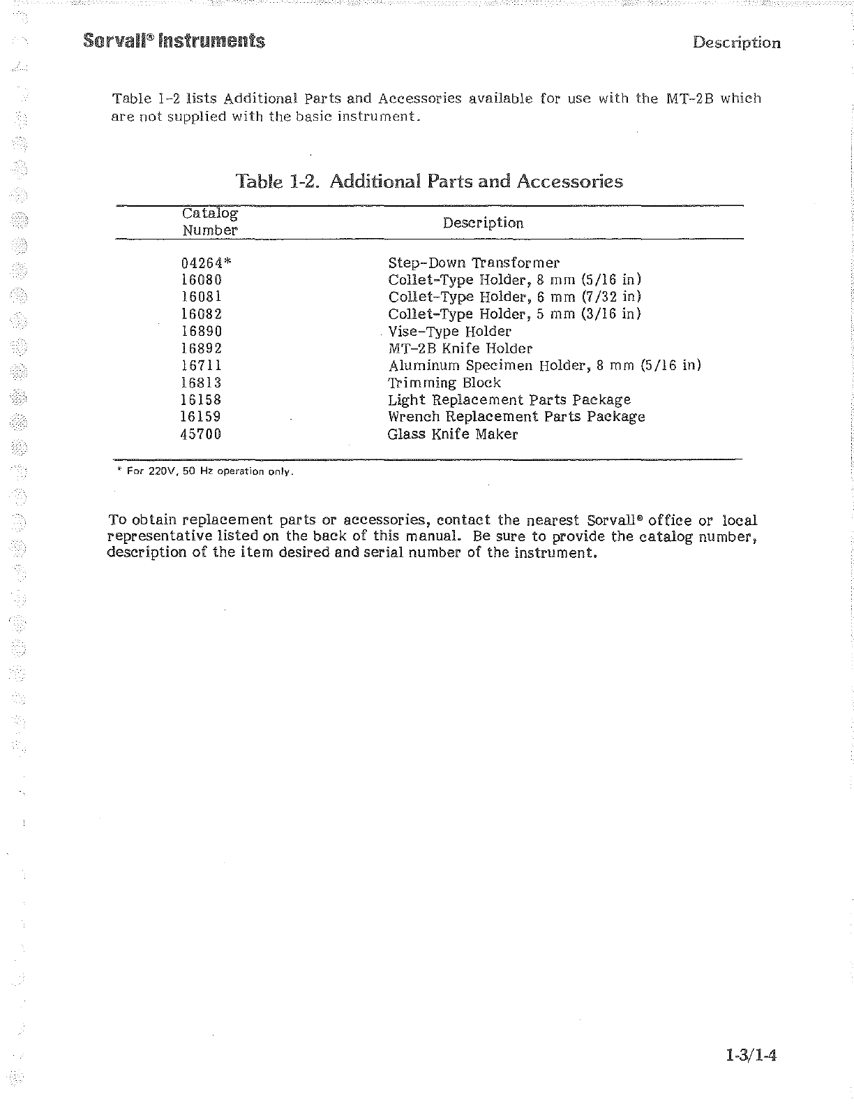
Table
l-2
lists
Additional
Parts
and
Accessories
available
for
use
with
the
MT-28
which
are
not
supplied
with
the
basic
instrument.
Table
1-2.
Additional
Parts
and
Accessories
Catalog
Number
04264*
16080
16081
16082
16890
16892
16711
16813
16158
16159
45700
• For
220V,
50 Hz operation only.
Description
Step-Down
Transformer
Collet-Type
Holder,
8
mm
(5/16
in)
Collet-Type
Holder,
6 mm (7/32 in)
Collet-Type
Holder,
5 mm (3/16 in)
Vise-Type
Holder
MT-28
Knife
Holder
Aluminum
Specimen
Holder,
8 mm
(5/16
in)
Trimming
Block
Light
Replacement
Parts
Package
Wrench
Replacement
Parts
Package
Glass
Knife Maker
To
obtain
replacement
parts
or
accessories,
contact
the
nearest
Sorvall®
office
or
local
representative
listed
on
the
back
of
this
manual.
Be
sure
to
provide
the
catalog
number,
description
of
the
item
desired
and
serial
number
of
the
instrument.
l-3/l-4

Installation
Section
2. INSTALLATION
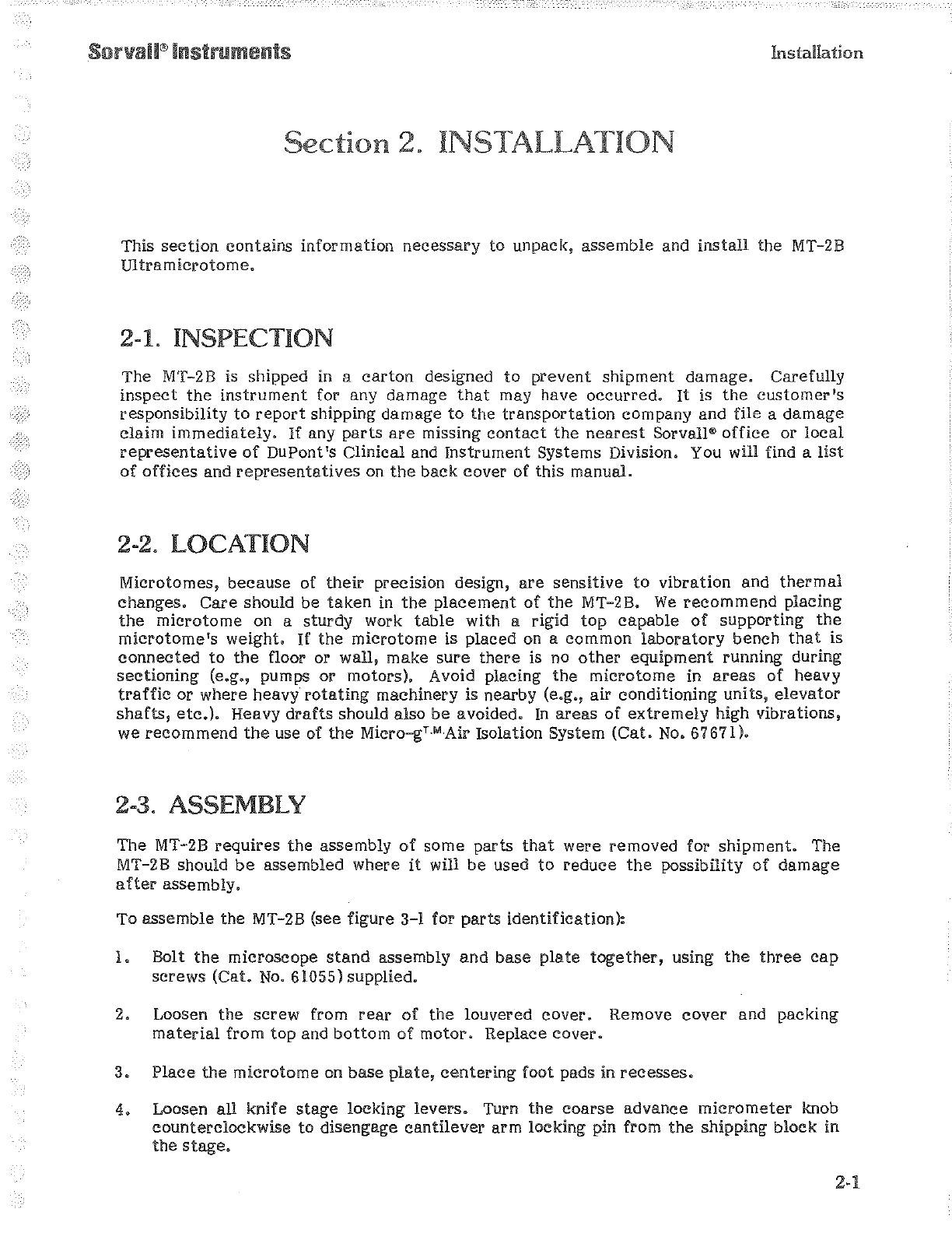
This
section
contains
information
necessary
to
unpack,
assemble
and
install
the MT-2B
mtramicrotome.
2-1. INSPECTION
The MT-2B is shipped in a
carton
designed
to
prevent
shipment
damage.
Carefully
inspect
the
instrument
for any
damage
that
may have
occurred.
It
is
the
customer's
responsibility
to
report
shipping damage
to
the
transportation
company and file a
damage
claim
immediately.
If
any
parts
are
missing
contact
the
nearest
Sorvall"'
office
or
local
representative
of
DuPont's Clinical and
Instrument
Systems Division. You will find a
list
of
offices
and
representatives
on
the
back
cover
of
this
manual.
2-2. LOCATION
Microtomes,
because
of
their
preciSIOn design,
are
sensitive
to
vibration
and
thermal
changes.
Care
should be
taken
in
the
placement
of
the
MT-2B.
We
recommend
placing
the
microtome
on a
sturdy
work
table
with a rigid
top
capable
of
supporting
the
microtome's
weight.
If
the
microtome
is placed on a
common
laboratory
bench
that
is
connected
to
the
floor or wall, make
sure
there
is no
other
equipment
running during
sectioning
(e.g., pumps or motors). Avoid placing
the
microtome
in
areas
of
heavy
traffic
or
where
heavy
rotating
machinery is nearby (e.g.,
air
conditioning
units,
elevator
shafts,
etc.).
Heavy
drafts
should also
be
avoided.
In
areas
of
extremely
high
vibrations,
we
recommend
the
use of
the
Micro-gT.MAir Isolation System
(Cat.
No.
67671).
2-3. ASSEMBLY
The MT-2B
requires
the
assembly
of
some
parts
that
were
removed
for
shipment.
The
MT-2B should
be
assembled where
it
will
be
used
to
reduce
the
possibility
of
damage
after
assembly.
To
assemble
the
MT-2B (see figure 3-1 for
parts
identification):
l.
Bolt
the
microscope
stand
assembly
and
base
plate
together,
using
the
three
cap
screws
(Cat.
No.
61055) supplied.
2. Loosen
the
screw
from
rear
of
the
louvered
cover.
Remove
cover
and packing
material
from
top
and
bottom
of
motor.
Replace
cover.
3.
Place
the
microtome
on
base
plate,
centering
foot pads in
recesses.
4.
Loosen all knife
stage
locking
levers.
Turn
the
coarse
advance
micrometer
knob
counterclockwise
to
disengage
cantilever
arm locking pin from
the
shipping
block
in
the
stage.

Installation
2-2
5.
To
release
locking pin, loosen
the
collet
holder,
turning
counterclockwise.
To
release
block,
loosen knife
clamping
thumbscrew.
(Note: pin and
block
should
be
retained
for
future
use in
the
event
the
microtome
is moved.)
6.
Place
handwheel
on
shaft
and
tighten
mounting
screw.
7.
Loosen
each
of
the
Phillips
screws
(about
one-quarter
turn)
at
lower
left
and
right
corners
of
front
panel
and on
the
top
of
the
cover
behind
the
upper
thickness
control
knob.
8.
Turn upper
thickness
control
knob
clockwise
to
zero,
then
turn
counterclockwise
to
position
10.
9.
Insert
microscope
arm
in
microscope
stand
assembly
and
tighten
locking
clamp
screw.
10.
Insert
microscope
holder
into
the
microscope
arm
and
tighten;
insert
the
microscope
into
holder
and
lock
in
place
with
side
levers.
11.
Plug
the
power
cord
into
power supply.
The MT-2B should
be
placed
8
em
to
13
em
(3
to
5 in) from
the
edge
of
the
work
surface.
2-4. ELECTRICAL REQUIREMENTS
The
motor
and
cold
light
source
require
a
power
supply
of
115
V,
60 Hz.
The
cord
is
fitted
with
a NEMA Type
5-15P
3-prong
molded
cap
with
ground
pin
and
parallel
blades.
For
power
supplies
200 V and 240
V,
50
and
60 Hz,
Cat.
No. 04264
Step-Down
Transformer
is
required.
2-5. MOVING THE MT-28 ULTRAMICROTOME
The MT-2B is a
delicate
instrument
and
must
be
moved
carefully.
If
there
is
a
possibility
the
MT-2B will
be
moved
to
another
building,
it
is
recommended
that
the
original
shipping
carton
and
unpacking
instructions
be
saved
for
repacking.
To move
the
MT-2B
to
a new
location,
reverse
the
assembly
procedure
outlined
in
paragraph
2-3,
then
place
the
microtome
in
its
shipping
container
reversing
the
order
of
the
unpacking
instructions.
2-6. CONTAMINATION
.----------1
WARNING
1---------,
Because
of
the
nature
of
samples
likely
to
be
processed
in
the
laboratory,
the
chance
of
contamination,
either
biological
or
radioactive,
is
possible.
Always
be
aware
of
this
possibility
and
take
normal
precautions.
Use
the
appropriate
decontamination
procedures
should
exposure
occur.
Installation
Should an
instrument
that
has
been
used
with
radioactive
or
pathogenic
material
require
servicing
by
DuPont
personnel,
either
at
the
customer's
laboratory
or
at
a DuPont
facility,
comply
with
the
following
procedure
to
ensure
the
safety
of
all
personnel:
®
Clean
the
instrument
to
be
serviced
of
all
encrusted
material
and
decontaminate
it
prior
to
servicing
by
the
DuPont
representative.
There
must
be
no
radioactivity
detectable
by
survey
equipment.
..
Complete
and
attach
Decontamination
Information
Certificate
(Sorval!®
Instruments
Form No. !PDP-59)
to
the
instrument.
If
an
instrument
to
be
serviced
does
not
have
a
Decontamination
Information
Certificate
attached
and,
in
DuPont's
opinion,
presents
a
potential
radioactive
or
biological
hazard,
the
DuPont
representative
will
not
service
the
equipment
until
proper
decontamination
and
certification
is
complete.
If
DuPont
receives
an
instrument
at
its
Service
facilities
which,
in
its
opinion, is a
radioactive
or
biological
hazard,
the
sender
will
be
contacted
for
instructions
as
to
disposition
of
the
equipment.
Disposition
costs
will
be
borne
by
the
sender.
Decontamination
Information
Certificates
are
included with
these
instructions.
Additional
certificates
are
available
from
the
local
Technical
or
Service
Representative.
ln
the
event
these
certificates
are
not
available,
a
written
statement
certifying
that
the
unit
has
been
properly
decontaminated
and
outlining
the
procedures
used
will
be
acceptable.
NOTE
The
Service
Representative
will
note
on a Field
Service
Repair
Report
if
decontamination
was
required,
and
if
so,
what
the
contaminant
was
and
what
procedure
was
used.
If
no
decontamination
was
required,
it
will
be
so
stated.
2-3/2-4

MT-2B
Parts,
Controls
and
Indicators
Section
3.
PARTS,
CONTROLS
&
INDICATORS
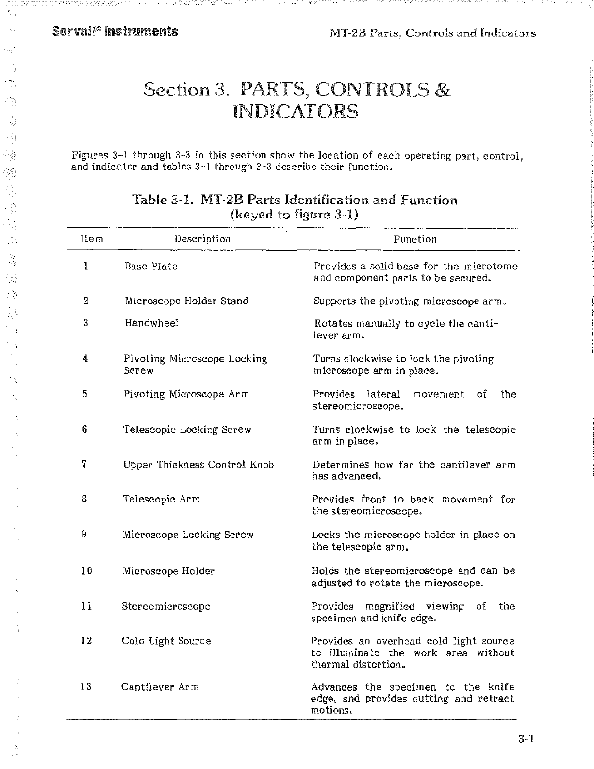
Figures
3-l
through 3-3 in this
section
show the
location
of
each
operating
part,
control,
and
indicator
and
tables
3-l
through 3-3 describe
their
function.
Item
l
2
3
4
5
6
7
8
9
10
!1
12
13
Table
3-1. MT-2B
Parts
Identification
and
function
(keyed
to
figure 3-1)
Description
Base
Plate
Microscope Holder
Stand
Handwheel
Pivoting
Microscope Locking
Screw
Pivoting
Microscope Arm
Telescopic Locking Screw
Upper Thickness
Control
Knob
Telescopic Arm
Microscope Locking Screw
Microscope Holder
Stereo
microscope
Cold Light Source
Cantilever
Arm
Function
Provides a solid base
for
the
microtome
and
component
parts
to
be
secured.
Supports
the
pivoting microscope
arm.
Rotates
manually
to
cycle
the
canti-
lever
arm.
Turns clockwise
to
lock
the
pivoting
microscope arm in
place.
Provides
lateral
movement
of
the
stereo
microscope.
Turns clockwise
to
lock
the
telescopic
arm
in
place.
Determines
how
far
the
cantilever
arm
has
advanced.
Provides
front
to
back
movement
for
the
stereomicroscope.
Locks
the
microscope holder in
place
on
the
telescopic
arm.
Holds
the
stereomicroscope
and
can
be
adjusted
to
rotate
the
microscope.
Provides magnified viewing
of
the
specimen
and
knife
edge.
Provides
an
overhead
cold
light
source
to
illuminate
the
work
area
without
thermal
distortion.
Advances
the
specimen
to
the
knife
edge, and provides
cutting
and
retract
motions.
3-1
MT-2B
Parts,
Controls
and
Indicators
Sorvall®Instruments
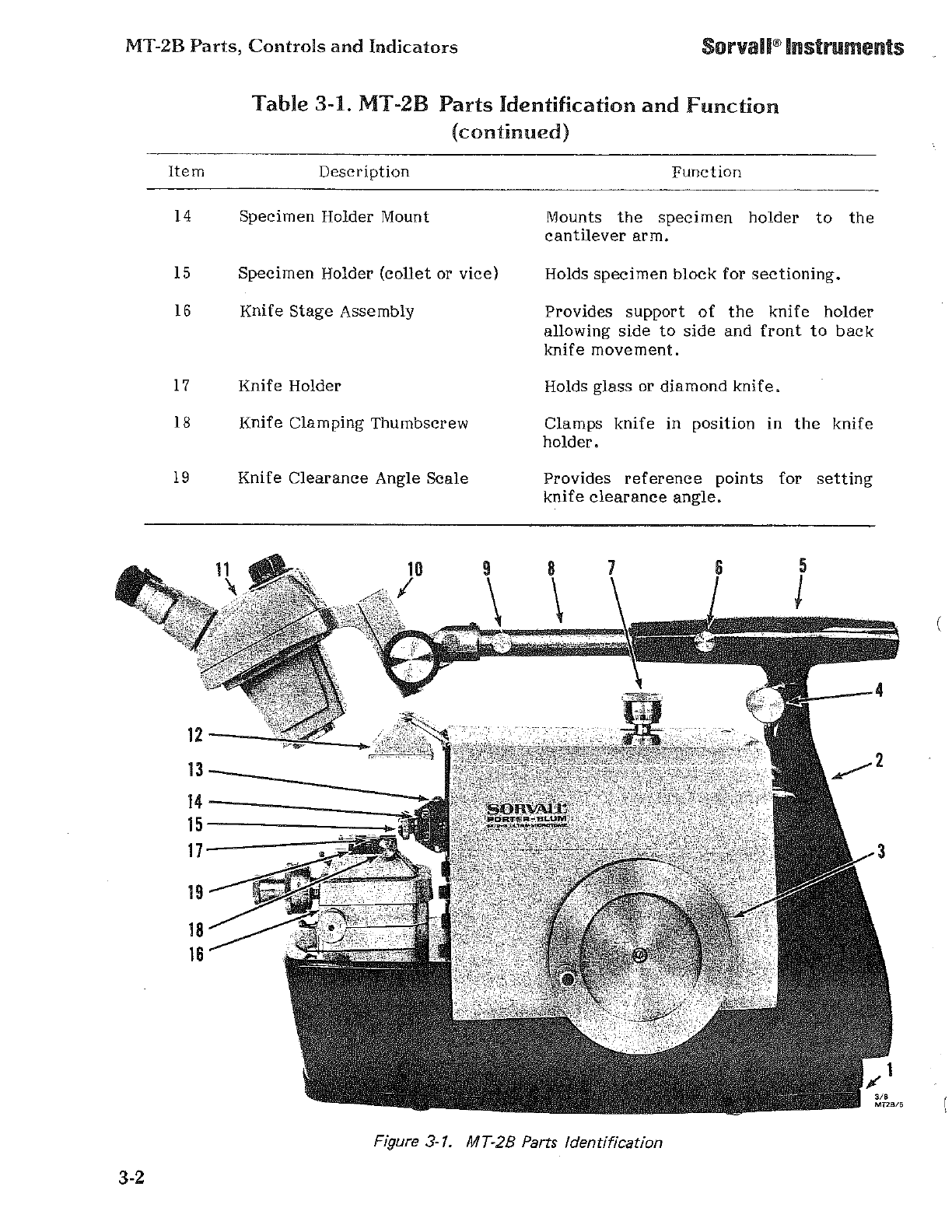
3-2
Table
3-1. MT-2B
Parts
Identification
and
Function
(continued)
Item
Description
14
Specimen
Holder
Mount
15
Specimen
Holder
(collet
or
vice)
16
Knife
Stage
Assembly
17
Knife
Holder
18
Knife
Clamping
Thumbscrew
19
Knife
Clearance
Angle
Scale
12--Z
13
_____
_
14-----_:
15------
....
;
17---~--:';
Function
Mounts
the
specimen
holder
to
the
cantilever
arm.
Holds
specimen
block
for
sectioning.
Provides
support
of
the
knife
holder
allowing
side
to
side
and
front
to
back
knife
movement.
Holds
glass
or
diamond
knife.
Clamps
knife
in
position
in
the
knife
holder.
Provides
reference
points
for
setting
knife
clearance
angle.
Figure 3-1. MT-28 Parts Identification
"'
MT2B/6
Sorvall®Instruments MT-2B
Parts,
Controls
and
Indicators
Item
1
2
3
4
5
6
7
8
9
10
ll
12
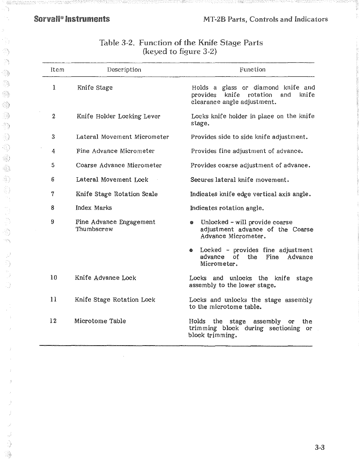
Table
3-2.
Function
of
the
Knife
Stage
Parts
(keyed
to
figure
3-2)
Description
Knife
Stage
Knife Holder Locking Lever
Lateral
Movement Micrometer
Fine Advance Micrometer
Coarse
Advance Micrometer
Lateral
Movement Lock
Knife
Stage
Rotation
Scale
Index Marks
Fine
Advance Engagement
Thumbscrew
Knife Advance Lock
Knife
Stage
Rotation
Lock
Microtome
Table
Function
Holds a glass or diamond
knife
and
provides knife
rotation
and
knife
clearance
angle
adjustment.
Locks knife holder in place
on
the
knife
stage.
Provides
side
to
side
knife
adjustment.
Provides fine
adjustment
of
advance.
Provides
coarse
adjustment
of
advance.
Secures
lateral
knife
movement.
Indicates
knife edge
vertical
axis
angle.
Indicates
rotation
angle.
• Unlocked
-will
provide
coarse
adjustment
advance
of
the
Coarse
Advance
Micrometer.
Locked -provides
advance
of
the
Micrometer.
fine
adjustment
Fine Advance
Locks and unlocks
the
knife
stage
assembly
to
the
lower
stage.
Locks and unlocks
the
stage
assembly
to
the
microtome
table.
Holds
the
stage
assembly or
the
trimming
block
during
sectioning
or
block
trimming.
3-3

MT-2B
Parts,
Controls
and
Indicators
Figure
3-2.
Knife Stage
Parts
3-4
2
4
5
6
7
Sorvall®Instruments MT-2B
Parts,
Controls
ami
Indicators
Item
l
2
3
4
5
6
7
8
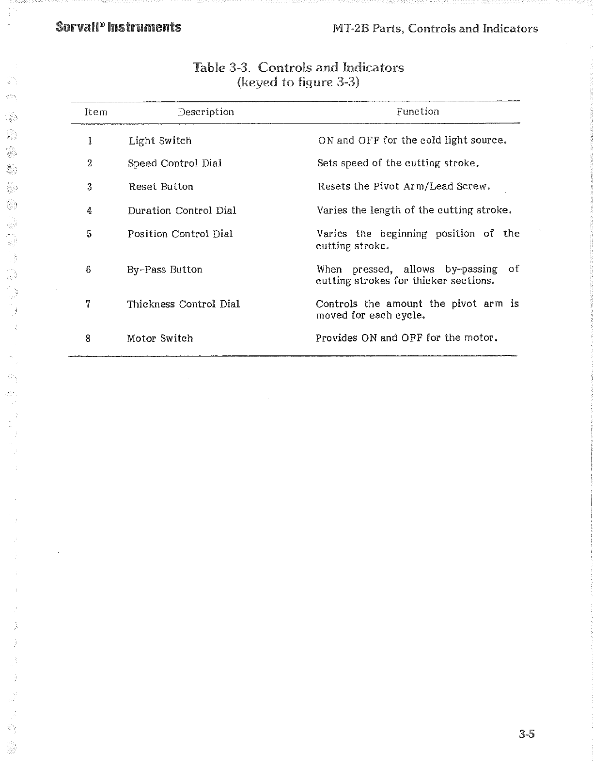
Table
3-3.
Controls
and
Indicators
(keyed
to
figure
3-3)
Description
Light
Switch
Speed
Control
Dial
Reset
Button
Duration
Control
Dial
Position
Control
Dial
By-Pass
Button
Thickness
Control
Dial
Motor Switch
Function
ON
and
OFF
for
the
cold
light
source.
Sets
speed
of
the
cutting
stroke.
Resets
the
Pivot
Arm/Lead
Screw.
Varies
the
length
of
the
cutting
stroke.
Varies
the
beginning
position
of
the
cutting
stroke.
When
pressed,
allows
by-passing
of
cutting
strokes
for
thicker
sections.
Controls
the
amount
the
pivot
arm
is
moved for
each
cycle.
Provides
ON
and
OFF for
the
motor.
3-5

MT-2B
Parts,
Controls
and
Indicators
Figure
3-3. Controls and Indicators
3-6
Sorvall®Instruments
2
3
4
5
3/8
MT2B/14
Table of contents
Other Sorvall Laboratory Equipment manuals


