Nivus NivuFlow 650 User manual
FLOW permanent
Instrumentation for Water Industry
NIVUS GmbH • Im Taele 2 • Germany-75031 Eppingen • Internet: www.nivus.com
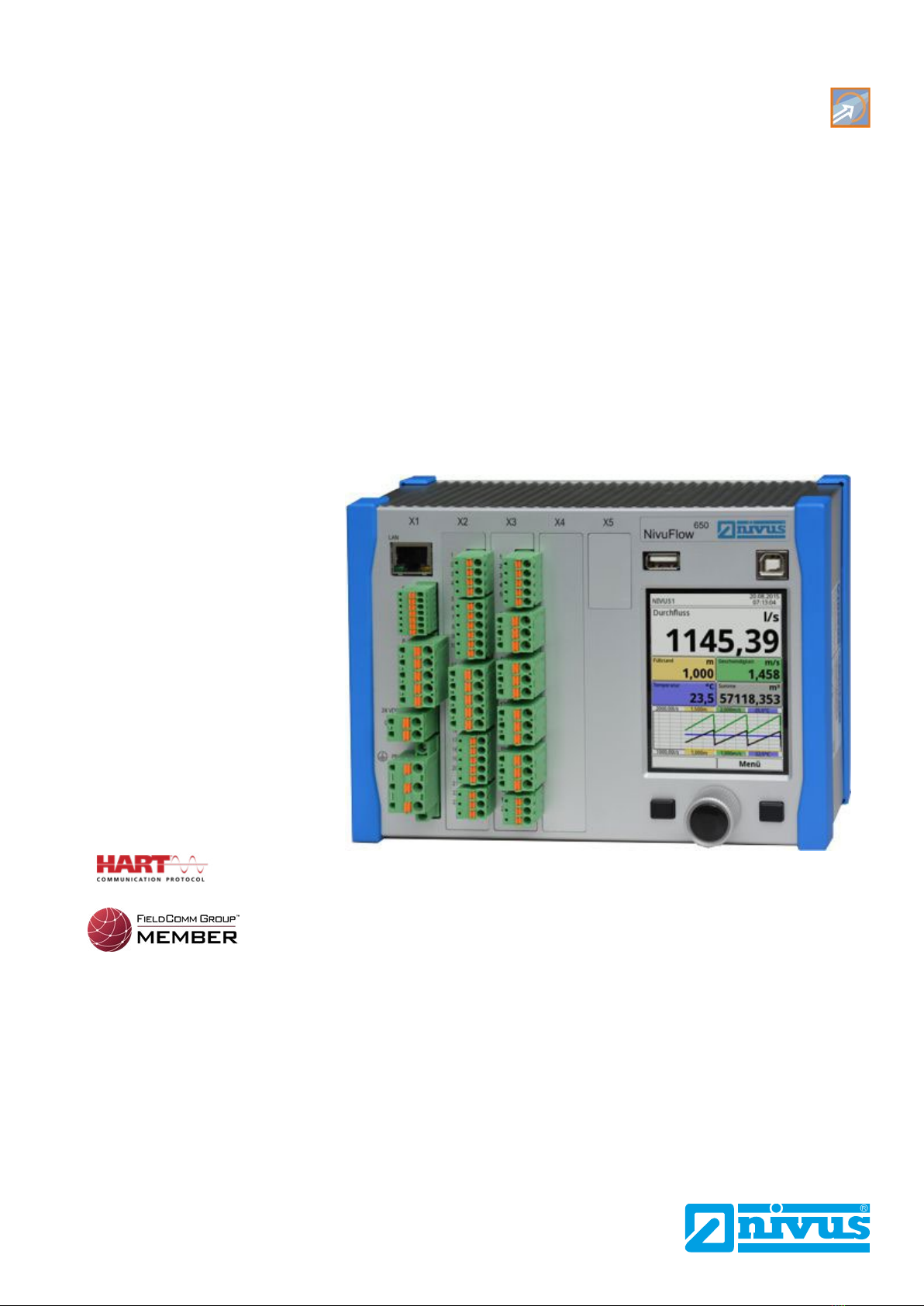
Flow Measurement Transmitter
NivuFlow 650
Instruction Manual
Firmware Revision: 2.4.x
Document revision: rev. 01 / 29.06.2020
Original Manual: German / rev. 01 as of 19.05.2020
Revised manual

Branches
page 2 NF 650 - rev. 01 / 29.06.2020
NIVUS AG, Switzerland
Burgstrasse 28
8750 Glarus, Switzerland
Phone +41 (0)55 6452066
Fax +41 (0)55 6452014
www.nivus.de
NIVUS, Austria
Muehlbergstrasse 33B
3382 Loosdorf, Austria
Phone +43 (0)2754 567 63 21
Fax +43 (0)2754 567 63 20
www.nivus.de
NIVUS Sp. z o.o., Poland
ul. Hutnicza 3 / B-18
81-212 Gdynia, Poland
Phone +48 (0)58 7602015
Fax +48 (0)58 7602014
www.nivus.pl
NIVUS, France
67870 Bischoffsheim, France
Phone +33 (0)388 9992 84
www.nivus.fr
NIVUS Ltd., United Kingdom
Wedgewood Rugby Road
Weston under Wetherley
Royal Leamington Spa
CV33 9BW, Warwickshire
Phone +44 (0)8445 3328 83
www.nivus.com
NIVUS Middle East (FZE)
Building Q 1-1 ap. 055
P.O. Box: 9217
Sharjah Airport International
Free Zone
Phone +971 6 55 78 224
Fax +971 6 55 78 225
www.nivus.com
NIVUS Korea Co. Ltd.
#2502, M Dong, Technopark IT Center,
32 Song-do-gwa-hak-ro,
Yeon-su-gu,
INCHEON, Korea 21984
Phone +82 32 209 8588
Fax +82 32 209 8590
www.nivus.com
NIVUS Vietnam
21 Pho Duc Chinh, Ba Dinh,
Hanoi, Vietnam
Phone +84 12 0446 7724
www.nivus.com

Copyrights and property rights
page 3NF 650 - rev. 01 / 29.06.2020
Copyrights and property rights
This document and its contents are proprietary to NIVUS GmbH and are not to be reproduced
or copied without the express written permission of NIVUS GmbH.
Violations will be liable for compensation.
Important Note
This instruction manual may exclusively - even in parts - be copied or translated in any
other way with the express written consent of NIVUS GmbH.
Translation
If the device is sold to a country in the European Economic Area (EEA) this instruction manual
must be translated into the language of the country in which the device is to be used.
Should the translated text be unclear, the original instruction manual (German) must be consul-
ted or one of the legally associated companies and subsidiaries of NIVUS group contacted for
clarification.
Copyright
No part of this publication may be reproduced, transmitted, sold or disclosed without prior
permission. Damages will be claimed for violations.
All rights reserved.
Names
The use of general descriptive names, trade names, trademarks and the like in this manual
does not entitle the reader to assume they may be used freely by everyone. They are often
protected registered trademarks even if not marked as such.

Instruction Manual
NivuFlow 650
page 4 NF 650 - rev. 01 / 29.06.2020
Document modifications
Rev. Modications Editor in
charge
Date
01 Complete revision: many features and functions added, layout redesi-
gned etc.
MoG 29.06.2020
00 First version based on the German document DMR 21.12.2015

Contents
page 5NF 650 - rev. 01 / 29.06.2020
Contents
COPYRIGHTS AND PROPERTY RIGHTS 3
DOCUMENT MODIFICATIONS 4
GENERAL 12
1 About this manual ................................................................................... 12
1.1 Applicable documentation .................................................................................12
1.2 Signsanddenitionsused ................................................................................12
1.3 Abbreviations used.............................................................................................13
2 Connections and Operating Elements .................................................. 13
2.1 Power Supply .....................................................................................................13
2.2 NivuFlow Operating Elements............................................................................14
2.3 Tasks of control elements...................................................................................14
2.4 Interfaces ...........................................................................................................15
SAFETY INSTRUCTIONS 16
3 General: Used Symbols and Signal Words........................................... 16
3.1 Valuation of the accident level............................................................................16
3.2 Warning notices on the product (option) ............................................................17
4 Safeguards and Precautions .................................................................. 17
5 Warranty ................................................................................................... 18
6 Liability Disclaimer.................................................................................. 18
7 Use in accordance with the requirements ............................................ 19
8 User’s Responsibilities ........................................................................... 19
9 Personnel requirements ......................................................................... 20
DELIVERY, STORAGE AND TRANSPORT 21
10 Delivery .................................................................................................... 21
11 Reception inspection .............................................................................. 21
12 Storage .................................................................................................... 21
13 Transport .................................................................................................. 21
14 Return ....................................................................................................... 21

Instruction Manual
NivuFlow 650
page 6 NF 650 - rev. 01 / 29.06.2020
PRODUCT SPECIFICATION 22
15 Product Construction and Overview ..................................................... 22
15.1 Dimensions of enclosure....................................................................................23
15.2 Connectable sensors ........................................................................................24
15.3 Deviceidentication ..........................................................................................24
16 Specications .......................................................................................... 25
17 Conguration .......................................................................................... 26
17.1 Device Types .....................................................................................................26
17.2 Additionally bookable Function Licences ...........................................................27
FUNCTIONAL DESCRIPTION 28
18 Operating Ranges.................................................................................... 28
19 Functional Principle ................................................................................ 29
19.1 Flow velocity detection .......................................................................................29
19.2 Flow Calculation.................................................................................................30
INSTALLATION AND CONNECTION 31
20 General Installation Instructions............................................................ 31
20.1 Avoidance of electrostatic discharge (ESD).......................................................31
20.2 Installation and Mounting versions.....................................................................31
20.3 Choosing the installation place ..........................................................................32
20.4 Transmitter fastening on DIN rail in control cabinets..........................................32
20.5 Field enclosure fastening and preparing electric installation .............................33
21 Electrical Installation............................................................................... 35
21.1 Wiring to the Terminal Blocks ...........................................................................35
21.2 Plans of terminal connections ..........................................................................37
21.3 Switching on voltage supply ..............................................................................42
21.3.1 Power supply DC............................................................................................42
21.3.2 Power supply AC ............................................................................................43
21.4 Relays ................................................................................................................44
22 Installation and Connection of Sensors................................................ 44
22.1 Sensor Installation Principles .............................................................................44
22.2 Installation of Clamp-On Sensors ......................................................................45
22.3 Installation of Wet Sensors ................................................................................45
22.4 Path arrangements.............................................................................................45
22.5 Cable and Cable length for connecting the sensors ..........................................46
22.6 Sensor Connection to NivuFlow.........................................................................46
22.6.1 Sensor connection 1-path measurement / 2-path measurement ..................46
22.7 Connection to/via Extension module NFE..........................................................47

Contents
page 7NF 650 - rev. 01 / 29.06.2020
23 Controller operation (function additionally bookable as licence) ...... 47
23.1 General ..............................................................................................................47
23.2 Control Section Setup ........................................................................................49
23.3 Regulator Mode Wiring Diagram........................................................................50
23.4 Control Algorithm................................................................................................50
24 Overvoltage Protection Measures ......................................................... 51
24.1 Overvoltage Protection for Power Supply ..........................................................52
24.2 Overvoltage Protection for mA-Inputs/Outputs ..................................................53
24.3 Overvoltage protection for communication interfaces ........................................53
24.4 Overvoltage protection for (transit time) sensor connectors ..............................54
24.4.1 Basic protection - equipotential bonding cable...............................................54
24.4.2 Extended protection - overvoltage protection “SonicPro T”............................54
OPERATION START-UP 58
25 Notes to users.......................................................................................... 58
26 Operation Basics ..................................................................................... 59
26.1 Display Overview ...............................................................................................59
26.2 Using the Control elements ...............................................................................59
26.3 Use/Entry using the letter block ........................................................................60
26.4 Use/Entry using the numeric keypad ................................................................61
26.5 Revision of parameters .....................................................................................61
26.6 Menus ................................................................................................................62
27 Information for the measurement with wet sensors ........................... 62
START-UP EXAMPLES 64
28 Example 1: Measurement in open Channels ........................................ 64
28.1 In General ..........................................................................................................64
28.2 Set Parameters of a system with multiple crossed paths...................................64
28.2.1 Simple parameter Setting...............................................................................64
28.2.2 Extended Parameter Setting ..........................................................................68
29 Example 2: Measurement in open waters ............................................. 69
29.1 In General ..........................................................................................................69
29.2 Setting Parameters of a Multi-Path System in >Channel< ................................70
SETTING PARAMETERS 74
30 General Programming ............................................................................ 74
30.1 Modicationofparameters:Exitmenus .............................................................74
30.2 Save Parameters ..............................................................................................74
30.3 Change Password .............................................................................................74

Instruction Manual
NivuFlow 650
page 8 NF 650 - rev. 01 / 29.06.2020
31 Parameter Functions............................................................................... 75
31.1 Main Menu ........................................................................................................75
31.2 Overview: Functions Top Menu Level ................................................................75
31.2.1 Application Menu / MP1 / MP2 / Combi..........................................................75
31.2.2 Data Menu .....................................................................................................76
31.2.3 System Menu .................................................................................................77
31.2.4 Communication Menu ....................................................................................78
31.2.5 Display Menu..................................................................................................78
31.2.6 Connections Menu .........................................................................................79
32 Application / MP1 / MP2 / Combi Parameter Menu ............................... 79
32.1 Setting parameters in Measurement place Menu .............................................79
32.1.1 Active..............................................................................................................80
32.1.2 Name of Measurement Place ........................................................................80
32.1.3 Path Arrangement ..........................................................................................81
32.1.4 Number of Paths ............................................................................................81
32.1.5 SonicPro T......................................................................................................81
32.1.6 Medium...........................................................................................................81
32.1.7 Medium Temperature......................................................................................82
32.1.8 ChannelProles .............................................................................................82
32.1.9 ChannelproleOset....................................................................................87
32.1.10 Sludge Level...................................................................................................87
32.1.11 3D-Preview.....................................................................................................87
32.1.12 Velocity evaluation..........................................................................................87
32.1.13 v-determination Low Levels ...........................................................................88
32.1.14 Low-Flow Suppression ...................................................................................90
32.1.15 Damping .........................................................................................................90
32.1.16 Stability...........................................................................................................91
32.2 Setting parameters in Measurement place Combi Menu ..................................91
32.3 Setting parameters in h-Sensors Menu..............................................................92
32.3.1 h-Sensor types ...............................................................................................92
32.3.2 Overlapped.....................................................................................................93
32.3.3 Deviation (abs.) ..............................................................................................94
32.3.4 Fallback ..........................................................................................................95
32.4 Setting parameters in v-Paths Menu..................................................................95
32.4.1 Active..............................................................................................................95
32.4.2 Sensor Types .................................................................................................95
32.4.3 Sensor Mounting Position ..............................................................................96
32.4.4 Weighting .......................................................................................................97
32.4.5 v-Minimum and v-Maximum ...........................................................................97
32.4.6 Coverage........................................................................................................97
32.4.7 v-Path Error ....................................................................................................97

Contents
page 9NF 650 - rev. 01 / 29.06.2020
32.5 Setting parameters in Inputs and Outputs (analog and digital) Menu ................98
32.5.1 Analog Inputs .................................................................................................98
32.5.2 Analog Outputs...............................................................................................99
32.5.3 Digital Inputs.................................................................................................102
32.5.4 Digital Outputs..............................................................................................103
32.6 Setting Parameters in Q-Control Menu (function bookable as extra licence) ..105
32.7 Setting Parameters in Diagnostics Menu ........................................................106
33 Data Parameter Menu............................................................................ 107
33.1 Trend................................................................................................................107
33.2 Total.................................................................................................................. 110
33.3 Day Totals ........................................................................................................ 110
33.4 USB stick.......................................................................................................... 112
33.5 Data storage..................................................................................................... 116
33.6 Operating hours .............................................................................................. 116
34 System Parameter Menu........................................................................117
34.1 Information ....................................................................................................... 117
34.2 Region settings ................................................................................................ 117
34.2.1 (Operation) Language .................................................................................. 118
34.2.2 Date Format.................................................................................................. 118
34.2.3 Units ............................................................................................................. 118
34.2.4 Data Units..................................................................................................... 119
34.3 Time/Date.........................................................................................................120
34.4 Error messages ...............................................................................................121
34.5 Service ............................................................................................................121
34.5.1 Service Level................................................................................................122
34.5.2 Change (System) Password.........................................................................122
34.5.3 Feature unlock .............................................................................................123
34.5.4 Reboot..........................................................................................................123
34.5.5 Restart Measurement...................................................................................123
34.5.6 Parameter reset............................................................................................124
34.5.7 Update NivuFlow ..........................................................................................124
34.5.8 Update h-Sensor .........................................................................................124
35 Communication Parameter Menu ........................................................ 125
35.1 TCP/IP .............................................................................................................125
35.2 Web server ......................................................................................................125
35.3 HART (extra function bookable as licence)......................................................126
35.4 Modbus ............................................................................................................127
36 Display Parameter Menu....................................................................... 129
37 Connections Parameter Menu ............................................................. 131

Instruction Manual
NivuFlow 650
page 10 NF 650 - rev. 01 / 29.06.2020
MAIN DISPLAY 132
38 General overview .................................................................................. 132
38.1 Display Flow in measurement places 1 and 2..................................................134
38.2 Display Level in measurement places 1 and 2.................................................134
38.3 Display Velocity in measurement places 1 and 2 ............................................135
38.4 Display Temperature in measurement places 1 and 2 .....................................136
38.5 Display Sum in measurement places 1 and 2..................................................136
38.6 Display Trend/Hydrograph in measurement places 1 and 2 ............................137
38.7 Display Flow in measurement place Combi .....................................................137
38.8 Display Measurement Place 1/2 in measurement place Combi.......................138
38.9 Display Total in Measurement Place Combi.....................................................139
DIAGNOSTICS 140
39 Diagnostics Menu Principles................................................................ 140
40 Diagnostics h-Sensors.......................................................................... 141
41 Diagnostics v-Paths ............................................................................. 142
42 Inputs and Outputs (analog and digital).............................................. 143
42.1 Analog Inputs ...................................................................................................144
42.2 Analog Outputs ................................................................................................144
42.3 Digital Inputs ....................................................................................................146
42.4 Digital Outputs..................................................................................................146
43 Q-Control (extra function bookable as licence).................................. 148
44 Signal Analysis ...................................................................................... 149
45 Simulation .............................................................................................. 154
ERROR MESSAGES 156
46 Error message indicated, Cause of failure and Troubleshooting ..... 156
MAINTENANCE AND CLEANING 166
47 Maintenance........................................................................................... 166
47.1 Maintenance Interval........................................................................................166
47.2 Customer Service Information..........................................................................166
48 Cleaning ................................................................................................. 167
48.1 Transmitter .......................................................................................................167
48.2 Sensors ............................................................................................................167
49 Dismantling/Disposal ........................................................................... 167
50 Installation of spare parts and parts subject to wear and tear ......... 168
51 Accessories .......................................................................................... 168

Instruction Manual
NivuFlow 650
page 12 NF 650 - rev. 01 / 29.06.2020
General
1 About this manual
Important note
READ CAREFULLY BEFORE USE.
KEEP IN A SAFE PLACE FOR LATER REFERENCE.
This instruction manual for the flow measurement transmitter NivuFlow 650 is for the intended
use of the device only. This manual is oriented exclusively to qualified expert personnel.
Read this instruction manual carefully and completely prior to installation and connection since
it contains relevant information on this product. Observe the notes and particularly follow the
warning notes and safety instructions.
If you should have problems to understand information contained within this instruction manual
contact one of the legally associated companies and subsidiaries of NIVUS group for further
support. The companies and subsidiaries of NIVUS group cannot be held responsible for
damage to persons or materials due to incorrectly understood information in this instruction
manual.
1.1 Applicable documentation
For the installation and operation of the complete system extra instruction manuals or technical
descriptions may be required apart from this manual.
• Technical Instructions Transit Time Sensors
• Installation Instructions Transit Time Sensors
• Technical Instructions NIVUS MODBUS TCP/RTU Application Interface for measure-
ment transmitters of the series NivuFlow 5xx, 6xx, 7xx and Energy Saver
• Technical Instructions Extension Module NFE
These manuals are provided with the auxiliary units or sensors and/or are available as down-
load on the NIVUS homepage.
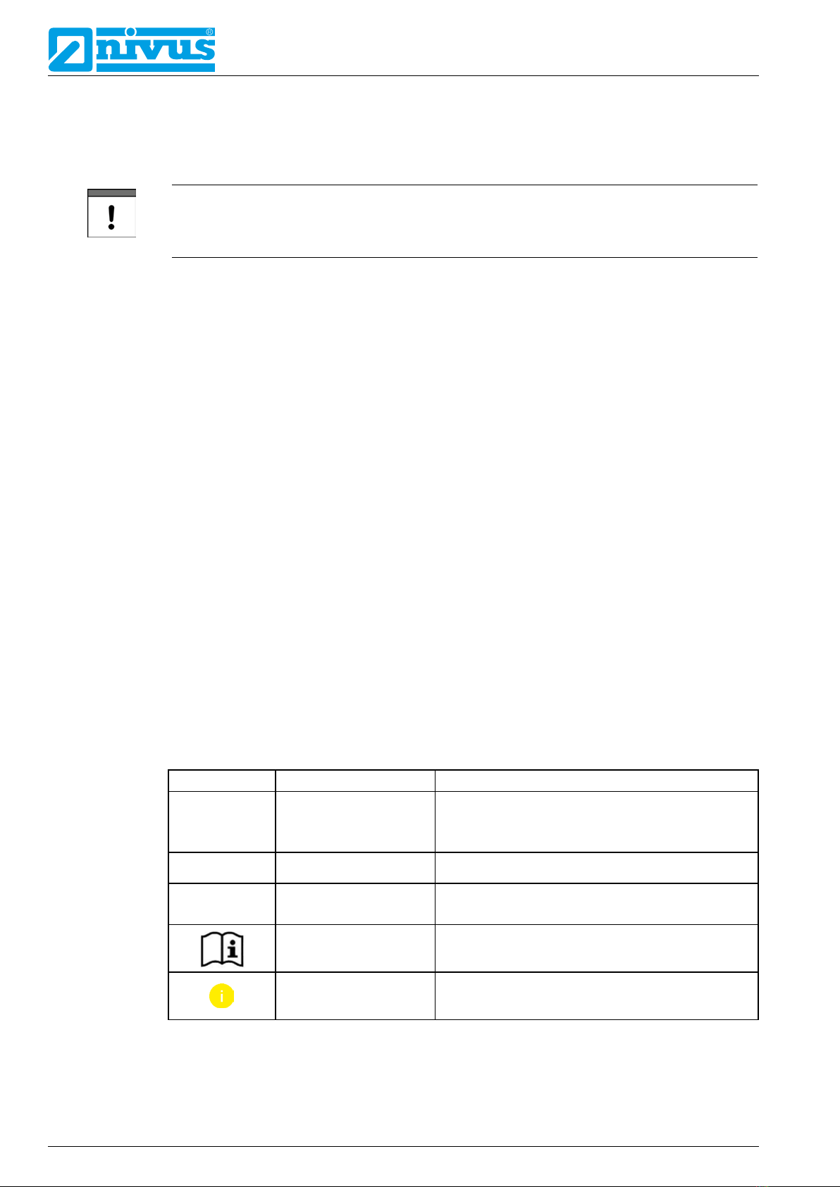
1.2 Signs and definitions used
Image Meaning Remark
Ü(Action) Step Action to be performed by you.
Note the numbering of action steps. Observe the
order of the steps.
cCross-reference Refers to further or detailed information.
>Text< Parameter or Menu Indicates a parameter or a menu that is selected
or described.
Reference to docu-
ment
Refers to an accompanying documentation.
Graphics/Table info Additional information in the legend of a graphic
or a table
Table 1-1 Structural elements within the manual

General
page 13NF 650 - rev. 01 / 29.06.2020
1.3 Abbreviations used
Colour code for wires and single conductors
The abbreviations of colours, wire and components follow the international colour code accor-
ding to IEC 60757.
BK black BN brown RD red
OG orange YE yellow GN green
BU blue VT violet GY grey
WH white PK pink TQ turquoise
GNYE green/yellow GD gold SR silver
2 Connections and Operating Elements
2.1 Power Supply
The connection for the power supply is located on the lower part of the terminal block X1.
1 Power supply DC
2 Power supply AC and earth conductor
Fig. 2-1 Electrical connections of power supply
Fc You can find a detailed connection plan in Sect. “21.2 Plans of terminal connections”.

Instruction Manual
NivuFlow 650
page 14 NF 650 - rev. 01 / 29.06.2020
2.2 NivuFlow Operating Elements
The NivuFlow is operated completely in dialogue mode supported by the graphs on the
display. To select individual menus and submenus use the rotary pushbutton as well as both
function keys.
1
2 3
1
4
Graphic display
2 Left function key
3 Rotary pushbutton
4 Right function key
Fig. 2-2 Operating elements
2.3 Tasks of control elements
Colour display
You can read all settings, when setting parameters and in diagnostics.
Left function key (Menu and/or Back)
This key (Menu) takes you from the main display to the main menu. The same key (Back) is
also used to exit the main menu and the submenus.
Rotary pushbutton
Use the rotary pushbutton to enter specific submenus. The functions can be selected using the
rotary pushbutton as well.
• Select the desired parameter or menus
• Navigation through the submenus and settings
• Selection of letters or numbers for parameter setting
Right function key (Input and/or Tab)
This key is used to confirm value entries (via numeric keys or letter keys).
For some parameters the right function key can be used as >Tab<. This Tab function is always
available when digits are visible in the upper right corner of the display. Then the Tab function
is used to switch between pages/displays. This applies to the following settings:
• Menu >Application<
Selecting the v-paths
Selecting the analog inputs / outputs
Selecting the digital inputs / outputs
Diagnostics of the v-paths

General
page 15NF 650 - rev. 01 / 29.06.2020
Diagnostics of the signal analysis
• Menu >Data<
Selection of Trend, Total and Day totals
Within the programming of multiple inputs/outputs or when programming several v-paths, the
right function key is used to jump from one input/output or v-path to the next.
Fc You will find a description on how to use the control elements in Sect. “26 Operation
Basics”.
2.4 Interfaces
The transmitter is equipped with various interfaces on the front panel.
1 Network interface (LAN)
2 BUS interface (RS485/RS232)
3 HART interface
4 USB-A interface (data transfer, parameter backup, device update)
5 USB-B interface (service)
Fig. 2-3 Available interfaces
Fc Descriptions of the individual interfaces see Sect. “35 Communication Parameter
Menu”.

Instruction Manual
NivuFlow 650
page 16 NF 650 - rev. 01 / 29.06.2020
Safety Instructions
3 General: Used Symbols and Signal Words
3.1 Valuation of the accident level
The general warning symbol indicates the risk of personal injuries or death. In the text
section the general warning symbol is used in conjunction with the signal words described
below.
DANGER Warnings in high degree of risk
Indicates a high-risk, imminently hazardous situation which will result in death or serious
injury if not avoided.
WARNING Warnings in medium degree of risk
Indicates a possible danger with medium risk which may result in a life-threatening situa-
tion or (severe) bodily injury if it is not avoided.
CAUTION Warnings in low-risk or property damages
Indicates a possible danger with moderate risk which may result in minor or moderate
personal injury or material damage if not avoided.
WARNING Danger by electric voltage
Indicates a hazard with a high risk of electric shock which may result in a life-threatening
situation or (severe) bodily injury if it is not avoided.
Important Note
Contains information that should be highlighted.
Indicates a potentially damaging situation which can result in damage to the product or to an
object in its environment.
Note
Contains information and facts.

Safety Instructions
page 17NF 650 - rev. 01 / 29.06.2020
3.2 Warning notices on the product (option)
General warning label
This symbol is for operators to refer to this manual.
Observing the information contained therein is required in order to maintain protection mea-
sures provided by the instrument during installation procedures and operation.
Protective conductor
This symbol refers to the protective conductor of the unit.
Depending on the mode of installation the instrument shall be operated solely connected to
an appropriate protective conductor according to applicable laws and regulations.
4 Safeguards and Precautions
Working with NIVUS instruments requires to observe and to follow the safety measures
and precautions below generally and at any time. These notes and warnings will not be
repeated for each description within the document.
WARNING Germ contamination
Parts can be contaminated with dangerous germs, especially if the sensors are used in
waste water applications. Therefore, appropriate precautions must be taken when contac-
ting cables and sensors.
Wear protective clothing.
WARNING Observe occupational safety regulations
Before starting and while executing installation work, observing the work safety regulations
needs to be checked constantly.
Disregarding these regulations may lead to personal injury.
WARNING Do not disable safety devices!
It is strictly prohibited to disable the safety devices or to change the way they work.
Disregarding this may lead to personal injury or site damage.
WARNING Disconnect the systems from mains
Maintenance, cleaning and/or repairs (by qualified personnel only) may only be performed
when de-energised.
Disregarding this warning may lead to electric shocks.
Putting into operation by trained experts only
The entire measurement system shall be installed and put into operation by trained expert
personnel only.
Integrated buffer battery
The integrated buffer battery may only be exchanged by NIVUS staff or personnel authori-
sed by NIVUS. Infringements lead to a limitation of the warranty (see Sect. “5 Warranty”).

Instruction Manual
NivuFlow 650
page 18 NF 650 - rev. 01 / 29.06.2020
5 Warranty
The device has been functionally tested before delivery. If it is used as intended (see Sect.
“7 Use in accordance with the requirements”) and the operating instructions, the applicable
documents (see Sect. “1.1 Applicable documentation”) and the safety notes and instructions
contained therein, are observed, no functional restrictions are to be expected and perfect
operation should be possible.
Fc Please also note in this regard the next Sect. “6 Liability Disclaimer”.
Limitation of warranty
In the event of non-compliance with the safety instructions and instructions in this document,
the companies of the NIVUS group of companies reserve the right to limit the warranty.
6 Liability Disclaimer
The legally associated companies and subsidiaries of NIVUS group assume no liability
• for damages owing to a change to this document. The legally associated companies
and subsidiaries of the NIVUS group reserve the right to change the contents of this
document and this disclaimer at any time and without any notice.
• for damages to persons or objects resulting from failure to comply with applicable
regulations. When connecting, commissioning and operating the sensors, all availa-
ble information and higher local legal regulations (in Germany e.g. VDE regulations)
such as applicable Ex regulations as well as safety requirements and regulations in
order to avoid accidents shall be adhered to.
• for damages to persons or objects resulting from improper use. For safety and
warranty reasons, all internal work on the instruments beyond that involved in normal
installation and connection, must be carried out only by qualified NIVUS personnel or
persons or companies authorised by NIVUS.
• for damages to persons or objects resulting from the use of instruments in technically
imperfect condition.
• for damages to persons or objects resulting from the use of instruments not in accor-
dance with the requirements.
• for damages to persons or objects resulting from failure to comply with safety
information contained within this instruction manual.
• for missing or incorrect measurement values or resulting consequential damages due
to improper installation.

Safety Instructions
page 19NF 650 - rev. 01 / 29.06.2020
7 Use in accordance with the requirements
Note
The instrument is intended solely for the purpose described below.
Modifying or using the instruments for any other purposes without the written consent of the
legally associated companies and/or subsidiaries of NIVUS group will not be considered as
use in accordance with the requirements.
The legally associated companies and subsidiaries of NIVUS group cannot be held respon-
sible for any damage resulting from improper use. The user alone bears any risk.
The NivuFlow 650 transmitter and associated sensor system is designed for continuous flow
measurement of slightly contaminated to clear, pure water-based liquids in partly or fully
filled pipes, channels or water bodies.
The measurement transmitter is designed and manufactured in accordance with the current
state of the art and with the recognised safety rules and regulations applicable at the time this
document is issued. Danger to persons or material damage cannot be completely ruled out,
however.
The maximum permissible limit values as specified in Sect. “16 Specifications” shall be nec-
essarily observed. Any case varying from these conditions which is not approved by NIVUS
GmbH in written form is left at the owner’s risk.
8 User’s Responsibilities
Observe and comply with all guidelines and requirements
In the EEA (European Economic Area) national implementation of the framework directive
89/391/EEC and corresponding individual directives, in particular the directive 2009/104/
EC concerning the minimum safety and health requirements for the use of work equipment
by workers at work, as amended, are to be observed and adhered to. In Germany e.g. the
Industrial Safety Ordinance must be observed.
Make sure to have a local operating permit available and observe the associated conditions.
In addition to this you must observe environmental requirements and local laws on the follow-
ing points:
• Personnel safety (accident prevention regulations)
• Safety of work materials and tools (safety equipment and maintenance)
• Disposal of products (laws on wastes)
• Disposal of materials (laws on wastes)
• Cleaning (cleansing agents and disposal)
Connections
Operators shall make sure prior to operating the instrument that during installation and initial
start-up the local regulations (such as regulations for electrical connection) are observed.
Keep the manual
Keep this manual in a safe place and make sure it is available for the users of this product at
any time.
Provide the manual
In case of selling the instrument this instruction manual shall be provided to the purchaser
since it is a part of the standard delivery.

Instruction Manual
NivuFlow 650
page 20 NF 650 - rev. 01 / 29.06.2020
9 Personnel requirements
Installation, commissioning and maintenance shall be executed only by personnel meeting the
demands as follows:
• Expert personnel with relevant training and appropriate qualification
• Personnel authorised by the plant operator
Qualified personnel
within the context of this documentation or the safety notes on the product itself are per-
sons who are sufficiently familiar with installation, mounting, starting up and operation of the
product and who have the relevant qualifications for their work; for example:
I. Training, instruction or authorisation to activate/deactivate, isolate, ground, and mark
electric circuits and devices/systems according to the safety engineering standards.
II. Education and instruction according to the standards of safety engineering regarding the
maintenance and use of adequate safety equipment.
III. First aid training
Table of contents
Other Nivus Transmitter manuals


Popular Transmitter manuals by other brands

RKI Instruments
RKI Instruments 65-2650RK-04 Operator's manual

M-system
M-system M1EXS-2 instruction manual

City Theatrical
City Theatrical Multiverse 5911 user manual

Q5X
Q5X CoachMic QT-AD10C quick start guide

Omega Engineering
Omega Engineering PRTXD Series user guide

M-system
M-system W5 Series instruction manual

Communications Specialties
Communications Specialties Fiberlink 7514 user manual

Magnetek
Magnetek Flex EX Series instruction manual

Emerson
Emerson Rosemount 3308 Reference manual

MG
MG 10AC instruction manual

Chauvet
Chauvet W-DMX Operation guide

GE
GE IFS VT1101M Installation/operation instructions warranty information


