Nivus OCM F User manual
FLOW permanent
Instruction Manual
Flow Measurement Transmitter OCM F
Firmware Revision: 4.00
Original manual: German / 16.02.2018
Rev. 05 / 06.04.2018

Instruction Manual
OCM F
page 2 OCM F - rev. 05 / 06.04.2018
NIVUS AG, Switzerland
Burgstrasse 28
8750 Glarus, Switzerland
Phone: +41 (0)55 6452066
Fax: +41 (0)55 6452014
swiss@nivus.com
www.nivus.de
NIVUS Austria
Mühlbergstrasse 33B
3382 Loosdorf, Austria
Phone: +43 (0) 2754 567 63 21
Fax: +43 (0) 2754 567 63 20
www.nivus.de
NIVUS Sp. z o.o., Poland
ul. Hutnicza 3 / B-18
81-212 Gdynia, Poland
Phone: +48 (0) 58 7602015
Fax: +48 (0) 58 7602014
www.nivus.pl
NIVUS France
14, rue de la Paix
67770 Sessenheim, France
Phone: +33 (0)3 88071696
Fax: +33 (0)3 88071697
www.nivus.fr
NIVUS U.K. Ltd.
Wedgewood Rugby Road
Weston under Wetherley
Royal Leamington Spa
CV33 9BW, Warwickshire
Phone: +44 (0)8445 3328 83
www.nivus.com
NIVUS Middle East (FZE)
Building Q 1-1 ap. 055
P.O. Box: 9217
Sharjah Airport International
Free Zone
Phone: +971 6 55 78 224
Fax: +971 6 55 78 225
middle-[email protected]
www.nivus.com
NIVUS Korea Co. Ltd.
#2502 M Dong, Technopark IT Center,
32 Song-do-gwa-hak-ro, Yeon-su-gu,
INCHEON, Korea 21984
Phone: +82 32 209 8588
Fax: +82 32 209 8590
www.nivus.com
NIVUS Vietnam
21 Pho Duc Chinh, Ba Dinh
Hanoi, Vietnam
Phone: +84 12 0446 7724
www.nivus.com
NIVUS Chile
Viña Cordillera Oriente 4565
Puente Alto, Santiago
Phone: +562 2266 8119
www.nivus.com

Copyrights and property rights
OCM F - rev. 05 / 06.04.2018 page 3
Copyrights and property rights
This document and its contents are proprietary to NIVUS GmbH and are not to be repro-
duced or copied without the express written permission of NIVUS GmbH.
Violations oblige to compensation.
Important Note
This manual may exclusively - even in parts - be copied or translated in any other way with
the express written consent of NIVUS GmbH.
Translation
If the device is sold to a country in the European Economic Area (EEA) this instruction manu-
al must be translated into the language of the country in which the device is to be used.
Should the translated text be unclear, the original instruction manual (German) must be con-
sulted or the manufacturer contacted for clarification.
Copyright
No part of this publication may be reproduced, transmitted, sold or disclosed without prior
permission. Damages will be claimed for violations. All rights reserved.
Names
The use of general descriptive names, trade names, trademarks and the like in this manual
does not entitle the reader to assume they may be used freely by everyone. They are often
protected registered trademarks even if not marked as such.

Instruction Manual
OCM F
page 4 OCM F - rev. 05 / 06.04.2018
Table of Contents
Copyrights and property rights 3
Table of Contents 4
General 7
1About this manual .................................................................................7
1.1 Applicable documentation.............................................................7
1.2 Signs and definitions used ............................................................8
1.3 Abbreviations used........................................................................8
1.3.1 Colour code for wires and single conductors..................................... 8
Safety Instructions 9
2Used symbols and signal words ...........................................................9
2.1 Valuation of the accident level.......................................................9
2.2 Warning notices on the product (option) .....................................10
3Safeguards and Precautions...............................................................10
4Liability disclaimer...............................................................................11
5Use in accordance with the requirements...........................................11
6User’s Responsibilities........................................................................12
7Personnel requirements......................................................................12
Product specification 13
8Overview .............................................................................................13
9Device identification............................................................................13
10 Specifications......................................................................................14
11 Configuration.......................................................................................16
11.1 Device Types...............................................................................16
11.2 Delivery........................................................................................16
11.3 Reception inspection...................................................................17
11.4 Storing .........................................................................................17
11.5 Transport.....................................................................................17
11.6 Return..........................................................................................17
11.7 Installation of spare parts and parts subject to
wear and tear...............................................................................17
12 Functional Principle.............................................................................18
12.1 In General....................................................................................18
12.2 Level Measurement using Pressure............................................18
12.3 Flow Velocity Detection...............................................................18
Installation and Connection 19
13 General Installation Instructions..........................................................19
14 Transmitter Installation and Connection .............................................19
14.1 General........................................................................................19
14.2 Enclosure Dimensions.................................................................20
14.3 Hints on how to avoid electrostatic discharge (ESD)..................21
14.4 Transmitter Installation................................................................21

Table of Contents
OCM F - rev. 05 / 06.04.2018 page 5
14.5 Electrical Installation....................................................................22
14.5.1 Transmitter Connection ................................................................... 22
14.5.2 KDA Sensor Connection.................................................................. 25
14.6 Power supply of OCM F ..............................................................28
14.7 Overvoltage Protection Precautions............................................29
14.8 Controller Mode...........................................................................32
14.8.1 General............................................................................................ 32
14.8.2 Construction of Measurement Section and Control Section............ 33
14.8.3 Connection for Controller Operation................................................ 34
14.8.4 Control Algorithm............................................................................. 35
Initial start-up 36
15 Notes to the user.................................................................................36
16 General principles ...............................................................................36
17 Operator Panel....................................................................................37
18 Display.................................................................................................37
19 Operation Basics.................................................................................39
Parameter Setting 40
20 Basics of Parameter Setting ...............................................................40
21 Operation Mode (RUN).......................................................................42
22 Display Menu (EXTRA).......................................................................44
23 Parameter Menu (PAR).......................................................................48
23.1 Parameter Menu “Measurement Place”......................................48
23.2 Parameter Menu “Level”..............................................................52
23.2.1 Information on how to connect i-Series sensors.............................. 55
23.3 Parameter Menu “Velocity”..........................................................56
23.4 Parameter Menu “Digital Inputs” .................................................56
23.5 Parameter Menu “Analog Output”...............................................57
23.6 Parameter Menu “Relay”.............................................................60
23.7 Parameter Menu “Control Unit”...................................................64
23.8 Parameter menu “Setup Parameter”...........................................68
23.9 Parameter menu “Storage mode”................................................69
24 Signal Input/Output Menu (I/O)...........................................................70
24.1 I/O submenu “Digital Inputs”........................................................70
24.2 I/O submenu “Analog Outputs”....................................................70
24.3 I/O submenu “Relay” ...................................................................71
24.4 I/O submenu “Data storage / USB” .............................................71
24.5 I/O submenu “Measure Data”......................................................73
24.6 I/O submenu “v-Sensor Info”.......................................................73
24.7 I/O submenu “v-Histogram”.........................................................74
24.8 I/O submenu “External Level”......................................................75
24.9 I/O submenu “Control unit”..........................................................75
24.10 I/O submenu “Test control unit – manual mode”.........................76
25 Calibration and Calculation Menu (CAL).............................................76
25.1 CAL submenu “Level”..................................................................76
25.2 CAL submenu “Flow Velocity”.....................................................77
25.3 CAL submenu “Analog Outputs” .................................................81
25.3.1 Basic Information on Simulation...................................................... 81

Instruction Manual
OCM F
page 6 OCM F - rev. 05 / 06.04.2018
25.4 CAL submenu “Relays” ...............................................................82
25.5 CAL submenu “Simulation” .........................................................83
Parameter tree / Menus available 84
Troubleshooting 92
Verification of the Measurement System 96
26 General................................................................................................96
27 Verification of Combi Sensor with Pressure Measurement Cell.........96
28 Verification of external Level Measurement........................................97
29 Verification and Simulation of Input and Output Signals.....................97
30 Verification of Flow Velocity Measurement.........................................98
Maintenance and Cleaning 99
31 Maintenance........................................................................................99
31.1 Maintenance interval ...................................................................99
31.2 Customer Service Information.....................................................99
32 Cleaning............................................................................................100
32.1 Transmitter ................................................................................100
32.2 Sensors .....................................................................................100
33 Dismantling/Disposal.........................................................................100
34 Accessories.......................................................................................101
Table “Manning-Strickler Coefficients” 102
Index 103
Approvals and Certificates 105

General
OCM F - rev. 05 / 06.04.2018 page 7
General
1 About this manual
Important Note
READ CAREFULLY BEFORE USE.
KEEP IN A SAFE PLACE FOR LATER REFERENCE.
This Instruction manual is intended for the initial start-up of the unit depicted on the title page.
This manual is oriented exclusively to qualified expert personnel.
Read this instruction manual carefully and completely prior to installation and connection
since it contains relevant information on this product. Observe the notes and particularly
follow the warning notes and safety instructions.
Keep this manual in a safe place and make sure it is available for the users of this product at
any time.
If you should have problems to understand information contained within this instruction
manual either contact the manufacturer or one of the distributors for further support. The
manufacturer cannot be held responsible for damage to persons or material due to incorrectly
understood information in this instruction.
In case of selling the instrument this instruction manual shall be provided to the purchaser
since it is a part of the standard delivery.
The operation of the complete system is described in the separate manual “Technical Instruc-
tion for Doppler Sensors”. Instructions on how to connect external level sensors are provided
with the standard delivery of the according sensors (e. g. NivuCompact, i-Series sensors…).
The installation of flow velocity sensors is described in the “Installation Instruction for Correla-
tion and Doppler Sensors“. This instruction manual is a part of the standard sensor delivery
and shall be read necessarily prior to sensor installation.
1.1 Applicable documentation
For the installation and operation of the complete system extra instruction manuals or tech-
nical descriptions may be required apart from this manual.
•Technical Instruction for Doppler Sensors
•Installation Instruction for Correlation and Doppler Sensors
These manuals are provided with the auxiliary units or sensors and/or are available as down-
load on the NIVUS homepage.

Instruction Manual
OCM F
page 8 OCM F - rev. 05 / 06.04.2018
1.2 Signs and definitions used
Image
Meaning
Remark
(Action) Step Action to be performed by you.
Note the numbering of action steps. Observe the
order of the working steps!
Cross-reference Reference to further or detailed information.
>Text< Parameter or Menu Indicates a parameter or a menu that is selected
or described.
Reference to document Refers to an accompanying documentation.
Table 1 Structural elements within the manual
1.3 Abbreviations used
1.3.1 Colour code for wires and single conductors
The abbreviations of colours, wire and components follow the international colour code ac-
cording IEC 757.
BK black RD red TR transparent
BU blue WH white GNYE green/yellow
GN green YE yellow BN brown
GY grey PK pink

Safety Instructions
OCM F - rev. 05 / 06.04.2018 page 9
Safety Instructions
2 Used symbols and signal words
2.1 Valuation of the accident level
The general warning symbol indicates the risk of personal injuries or death. In the text sec-
tion the general warning symbol is used in conjunction with the signal words described
below.
DANGER Warnings in high degree of risk
Indicates a high-risk, imminently hazardous situation which will result in death or serious
injury if not avoided.
WARNING Warnings in medium degree of risk
Indicates a possible danger with medium risk which may result in a life-threatening situa-
tion or (severe) bodily injury if it is not avoided.
CAUTION Warnings in low-risk or property damages
Indicates a possible danger with moderate risk which may result in minor or moderate per-
sonal injury or material damage if not avoided.
WARNING Danger by electric voltage
Indicates a hazard with a high risk of electric shock which may result in a life-threatening
situation or (severe) bodily injury if it is not avoided.
Important Note
Contains information that should be highlighted.
Indicates a potentially damaging situation which can result in a damage of the product or an
object in its environment.
Note
Contains information and facts.

Instruction Manual
OCM F
page 10 OCM F - rev. 05 / 06.04.2018
2.2 Warning notices on the product (option)
General warning label
This symbol is for operators to refer to this instruction manual.
Observing the information contained therein is required in order to maintain protection
measured provided by the instrument during installation procedures and operation.
Protective conductor
This symbol refers to the protective conductor of the unit.
Depending on the mode of installation the instrument shall be operated solely connected to
an appropriate protective conductor according to applicable laws and regulations.
3 Safeguards and Precautions
Working with NIVUS instruments requires to observe and to follow the safety
measures and precautions below generally and at any time. These notes and warnings
will not be repeated for each description within the document.
WARNING Germ contamination
Please note that due to the operation in the waste water field the measurement system and
cables may be loaded with dangerous disease germs. Respective precautionary measures
must be taken to avoid damage to one’s health.
Wear protective clothing.
WARNING Observe occupational safety regulations
Before starting installation work, observing the work safety regulations need to be checked.
Disregarding may lead in personal injury.
WARNING Do not disable safety devices
It is strictly prohibited to disable the safety devices or to change the way they work.
Disregarding may lead in personal injury.
WARNING Disconnect the systems from mains
Maintenance, cleaning and/or repairs (by qualified personnel only) may only be performed
when de-energised.
Disregarding may lead to electric shocks.
Putting into operation by trained experts only
The entire measurement system shall be installed and put into operation by trained expert
personnel only.
Integrated buffer battery
The exchange of the integrated buffer battery shall be carried out by NIVUS staff or per-
sonnel authorised by NIVUS only. Otherwise the guarantee expires.

Safety Instructions
OCM F - rev. 05 / 06.04.2018 page 11
4 Liability disclaimer
The manufacturer reserves the right to change the contents of this document including this li-
ability disclaimer without prior notice and cannot be held responsible in any way for possible
consequences resulting from such changes.
For connection, initial start-up and operation as well as maintenance of the unit the following
information and higher legal regulations of the respective country (in Germany e. g. VDE reg-
ulations) such as applicable Ex regulations as well as safety requirements and regulations in
order to avoid accidents shall be observed.
All operations on the device which go beyond installation or connection measures in principle
shall be carried out by NIVUS staff or personnel authorised by NIVUS due to reasons of safe-
ty and guarantee.
Operate the transmitter only in technically perfect working order.
Improper Use
Not being operated in accordance with the requirements may impair the safety. The manufac-
turer is not responsible for failures resulting from improper use.
5 Use in accordance with the requirements
Note
The instrument is intended solely for the purpose described below.
Modifying or using the instruments for any other purposes without the manufacturer’s writ-
ten consent will not be considered as use in accordance with the requirements.
The manufacturer cannot be held responsible for any damage resulting from improper use.
The user alone bears any risk.
The permanent flow meter Type OCM F including the respective sensor technology is intend-
ed to be used for continuous flow measurement and control tasks of slight to heavy polluted
media in part filled and permanent full pipes, channels or similar.
The flow meter is designed and manufactured in accordance with the current state of the art
and with the recognised safety rules and regulations applicable at the time this document is
issued. Danger to persons or material damage cannot be completely ruled out, however.
The maximum permissible limit values as specified in chapter “10 Specifications” shall be
necessarily observed. Any case varying from these conditions which is not approved by
NIVUS GmbH in written form is left at the owner’s risk.
Ex protection
The Ex-version of the transmitter is designed to be used in areas with explosive atmospheres
(zone 1).
Approval measurement transmitter: II (2) G [Ex ib Gb] IIB
WARNING Risk of personal injury due to explosion hazard
Install the transmitter out of Ex zones!
The Ex approval of the sensors is part of the concerning manual and/or Technical Descrip-
tion.
The approval is valid only in conjunction with the according identification on the transmit-
ter’s or sensor’s nameplate.
The Ex approval of the sensors is part of the “Technical Instructions for Doppler Sensors”.
Instruction Manual
OCM F
page 12 OCM F - rev. 05 / 06.04.2018
Conformity certificates and test certificates
For installation and commissioning the conformity certificates as well as the test certificates
issued by the respective authorities shall be followed.
The Ex version of the OCM F is adjusted solely to NIVUS Doppler sensors Type KDA re-
garding the intrinsically safe system review according to EN60079-25.
In the event of using sensors by third-party manufacturers the operator shall carry out a
system review according to EN 60079-25!
The required specifications of the Ex version of the OCM F can be found in the according
EC type examination certificate IBExU07ATEX1081.
6 User’s Responsibilities
Important Note
In the EEA (European Economic Area) national implementation of the framework directive
89/391/EEC and corresponding individual directives, in particular the directive 2009/104/EC
concerning the minimum safety and health requirements for the use of work equipment by
workers at work, as amended, are to be observed and adhered to.
In Germany e. g. the Industrial Safety Ordinance must be observed.
Make sure to have a local operating permit available and observe the associated conditions.
In addition to this you must observe environmental requirements and local laws on the follow-
ing points:
•Personnel safety (accident prevention regulations)
•Safety of work materials and tools (safety equipment and maintenance)
•Disposal of products (laws on wastes)
•Disposal of materials (laws on wastes)
•Cleaning (cleansing agents and disposal)
Connections
Operators shall make sure prior to operating the instrument that during installation and initial
start-up the local regulations (such as regulations for electrical connection) are observed.
7 Personnel requirements
Installation, commissioning and maintenance shall be executed only by personnel meeting
the demands as follows:
•Expert personnel with relevant training an appropriate qualification
•Personnel authorised by the plant operator
Qualified personnel
within the context of this documentation or the safety notes on the product itself are per-
sons who are sufficiently familiar with installation, mounting, starting up and operation of
the product and who have the relevant qualifications for their work; for example:
I. Training, instruction or authorisation to activate/deactivate, isolate, ground, and
mark electric circuits and devices/systems according to the safety engineering
standards.
II. Education and instruction according to the standards of safety engineering regard-
ing the maintenance and use of adequate safety equipment.
III. First aid training
Product specification
OCM F - rev. 05 / 06.04.2018 page 13
Product specification
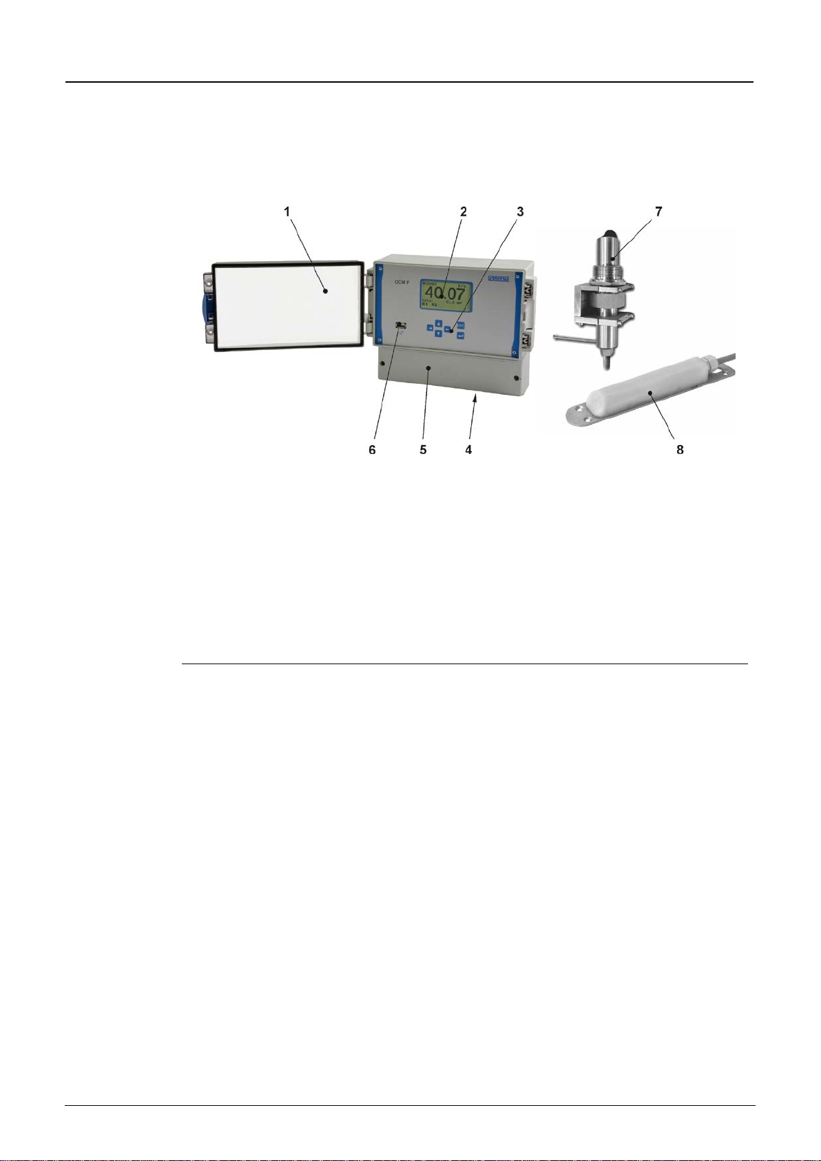
8 Overview
1 Clear view door
2
Graphic Display
3 Keypad
4 Preparations for Cable Glands
5 Terminal Clamp Housing
6 USB-A-Interface
7 Pipe Sensor with retaining element
8 Wedge Sensor (flow velocity)
Fig. 8-1 Overview
9 Device identification
The instructions contained within this manual are valid only for the type of device specified on
the title page. The name plate is fixed on top of the enclosure and contains the following:
•Name and address of the manufacturer
•CE label
•Information on type and series, serial no. if available.
•Year of manufacture: the first four digits of the serial number represent the year and the
week number of manufacture (1804 OCF …..)
•Additional Ex identification for Ex-version devices (as mentioned in chapter “5 Use in
accordance with the requirements“).
In case of enquiries and ordering replacement parts it is important to specify article number
as well as the serial number of the respective transmitter or sensor. This ensures correct and
quick processing.
Instruction Manual
OCM F
page 14 OCM F - rev. 05 / 06.04.2018
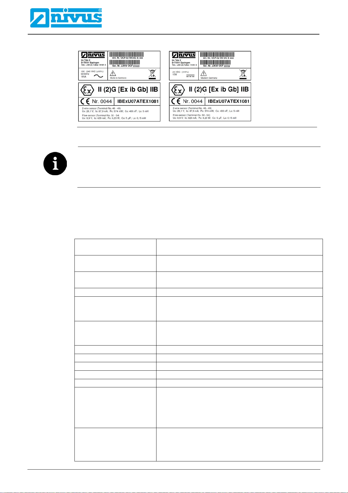
Fig. 9-1 Nameplates AC/DC (Ex versions)
Check the nameplates
Check the delivered instrument for accordance with your order by identifying the name-
plates.
Check the nameplates for correct specification of the power supply.
The EU-Type examination certificate (incl. appendix) and the declaration of
conformity are located at the end of the manual.
10 Specifications
Power supply
100…240 V AC, +10 % / -15 %, 47…63 Hz
24 V DC, ±15 %, 5 % residual fluctuation
Power consumption
AC: max. 18 VA, typ. 7 VA
DC: max. 15 W, typ. 6 W
Enclosure
Material: Polycarbonate
Weight: approx. 1200 g
Protection
IP65
Operating conditions
Protection class I
Overvoltage category II
Pollution degree 2
Altitude
AC unit for use in altitudes up to 3000 m above MSL.
At relay voltages >150 V the use is restricted to an altitude
of max. 2000 m (AC and DC units)
Operating temperature
-20 °C…+60 °C / for Ex: -20 °C…+40 °C
Storage temperature
-30 °C…+70 °C
Max. humidity
90 %, non-condensing
Display
Back-lit full graphic LCD, 128x64 pixel
Operation
6 keys, menu driven in German, English, French and Polish
Inputs
1x 4…20 mA for external level measurement (2-wire sensor)
2x 0/4…20 mA with 12 bit resolution for external level
measurement and external set points
4x digital input
1x compact Doppler active sensor, type KDA, connectable
Outputs
3x 0/4...20 mA, load 500 Ohm, 12 bit resolution, accuracy
better than 0.1 % (after adjustment)
5 switchable relays, loadable up to 230 V AC / 2 A
(cos.ϕ0.9)

Product specification
OCM F - rev. 05 / 06.04.2018 page 15
Controller
Three-step controller, quick close control, adjustable slide
valve position in error case
Data memory
4 MB, 64512 points, for programming and readings memory;
read-out via front-side USB stick
Storage cycle
1 minute to 1 hour
Ex approval (option)
II (2) G [Ex ib Gb] IIB
Sensor circuits
Ignition protection type Ex ib IIB
2-wire sensors per channel
Terminal no. 46…49
UO 26.1 V
IO87.9 mA
PO574 mW (linear characteristics)
CO400 nF
LO5 mH
Flow sensors
Terminal no. 50…54
UO9.9 V
IO629 mA
PO6.2 W (rectangular characteristics)
CO5 µF
L
O
0.15 mH
Data circuits
RS485 galvanically connected to sensor circuit
Us 5 V
The maximum values also apply to concentrated capacitance / inductors that can be
switched on.
Table 2 Specifications
The type examination certificate can be found at the end of this manual.
Sensors
Observe the specifications of the according sensors as described in the respective instruction
manuals or technical descriptions.

Instruction Manual
OCM F
page 16 OCM F - rev. 05 / 06.04.2018
11 Configuration
11.1 Device Types
The OCM F transmitter is available in different versions as shown in the overview table
below.
The transmitters primarily vary in terms of power supply and Ex-protection. The current type
of device is indicated by the article number, which can be found on a weatherproof label on
the bottom of the enclosure.
From this article key the type of device can be specified.
OCF
Type
02
Standard version for various pipe and channel shapes.
5 relays, 3 mA outputs (galv. isolated), 1 mA input (galv. isolated with
2-wire sensor supply) or for external level measurement,
integrated 3-step controller
Construction
W0
Wall mount enclosure IP65
Power supply
AC
85…265 V AC, 47…63 Hz
DC
20…28 V DC
ATEX approval
0
None
E
Intrinsically safe sensor supply in
Ex-Zone 1
OCF
02
W0
Table 3 Type key for measurement transmitter OCM F
11.2 Delivery
The standard delivery of the transmitter OCM F contains:
- Measurement transmitter OCM F
- The instruction manual including the certificate of conformity and approvals. It contains
any relevant information on how to operate the measurement system.
Check additional accessories depending on your order and according to the delivery note.

Product specification
OCM F - rev. 05 / 06.04.2018 page 17
11.3 Reception inspection
Check the packaging for visible damage immediately after receipt. Any possible damage in
transit shall be instantly reported to the carrier. Furthermore a written report shall be sent to
NIVUS GmbH in Eppingen.
Incomplete deliveries shall be reported in writing either to your local representative or directly
to the NIVUS head office in Eppingen within two weeks.
Important note
Mistakes cannot be rectified later.
11.4 Storing
Observe the minimum and maximum values on environmental conditions such as tempera-
ture and humidity according to chapter “10 Specifications”.
The measurement transmitter shall be protected from corrosive or organic solvent vapours,
radioactive radiation as well as strong electromagnetic radiation.
Always store the instrument in its original packaging.
11.5 Transport
Do not expose the system to heavy shocks or vibrations.
Use the original packaging for transport.
11.6 Return
In case of a required reshipment return the unit at customer cost to NIVUS GmbH in Ep-
pingen using the original packaging.
Insufficiently franked shipments will not be accepted.
11.7 Installation of spare parts and parts subject to wear and tear
We herewith particularly emphasise that replacement parts or accessories not supplied by
NIVUS moreover are not certified and approved by NIVUS too.
Installation and/or the use of such products hence may negatively influence predetermined
constructional characteristics of the measurement system or even lead to instrument failures.
NIVUS cannot be held responsible for any damage resulting due to the use of non-original
parts and non-original accessories.
You can find original manufacturer spare parts or accessories in chapter “34
Accessories” and/or in the valid price list.

Instruction Manual
OCM F
page 18 OCM F - rev. 05 / 06.04.2018
12 Functional Principle
12.1 In General
The OCM F is a permanent measurement system for flow measurement and flow control.
The device is designed to be used primarily in slight to heavy polluted media with various
compositions. It can be operated in partial and permanent filled channels and pipes with vari-
ous shapes and dimensions.
Important note
The measurement method is based on the ultrasound Doppler principle. Hence, it is indis-
pensable for the system’s capability to work that the water contains particles which are able
to reflect the ultrasonic signal sent by the sensor (dirt particles, gas bubbles or similar).
OCM F transmitters utilise a compact active Doppler sensor (KDA sensor). The KDA wedge
sensor is available as flow velocity and as combi sensor. KDA combi sensors simultaneously
determine the flow level along with the flow velocity by using a built-in pressure measurement
cell. KDA pipe sensors, however, are available only as flow velocity sensors. Detailed infor-
mation on the KDA sensors can be found in the Technical Description for Doppler Sensors.
12.2 Level Measurement using Pressure
The combi sensor type “KDA” additionally contains a hydrostatic level measurement via inte-
grated pressure measurement cell. The piezo-resistive pressure sensor operates according
to the relative pressure principle; i. e. the pressure of the standing water column above the
sensor is direct proportional to the flow level. During initial start-up procedure, the pressure
sensor is going to be adjusted by entering a manually investigated reference value.
12.3 Flow Velocity Detection
The flow velocity sensor, type “KDA” operates according to the continuous Doppler principle
(CW-Doppler) using 2 built-in piezo crystals with a slope of 45°. The crystal surfaces are
arranged parallel to the slope of the flow velocity sensor. One of the crystals continuously op-
erates as ultrasonic transmitter, the other one as receiver detecting the reflected ultrasonic
signal.
The sensor enclosure enables acoustic coupling of the high-frequency ultrasonic signal be-
tween piezo crystal/enclosure and enclosure/medium. Due to that reason an ultrasonic signal
with an angle of 45° is sent permanently against the flow direction of the medium to be
measured. As soon as the signal hits dirt particles, gas bubbles or similar a portion of the
sonic energy is reflected, being converted into an electric signal by the receiving crystal sub-
sequently.
Caused by the movement of the reflecting particles in relation to the acoustic source the fre-
quency of the ultrasonic signal is shifted. The resulting frequency shift is directly proportional
to the particles’ movement within the medium and hence represents the flow velocity.
The sensor processes the received reflection signal, converting it to be sent to the transmit-
ter. Due to varying velocities within the flow profile, vorticity, rotation of single reflecting parti-
cles, surface waves etc. a frequency mixture is emerging. This mixture is evaluated directly
within the KDA sensor regarding statistic considerations related to average flow velocity. The
frequency mixture is indicated on the transmitter display in >I/O / v-Histogram< (see chapter
“24.7 I/O submenu “v-Histogram””.
It is recommended to verify the measurement if conditions are disadvantageous from a hy-
draulic standpoint. Verification should not be based on the CW-Doppler method since in this
case it is not possible to spatially allocate recorded flow velocities.
In this case the VDI/VDE Directive 2640 is very helpful and important. NIVUS recommends
the portable meter Type >PVM/PD< or >PCM Pro< as calibration measurement or the NIVUS
initial start-up service.

Installation and Connection
OCM F - rev. 05 / 06.04.2018 page 19
Installation and Connection
13 General Installation Instructions
For electric installation the local regulations in the respective countries (in Germany e. g.
VDE 0100) must be referred to.
WARNING Separate protection
The OCM-F power supply must be separately protected by a 6 A slow-blow fuse and has to
be isolated from other facility parts (separate turn-off, e. g. by using an automatic cut-out
with >B< characteristics).
Before feeding the rated voltage the transmitter and sensor installation must be correctly
completed. The installation should be carried out by qualified personnel only.
Further statutory standards, regulations and technical rulings have to be taken into account.
All outer circuits, wires and lines connected to the device must have a minimum isolation re-
sistance of 250 kOhm. If the voltage exceeds 42 V DC an isolation resistance with 500 kOhm
min. will be required.
The cross-sectional dimension of the power supply wires must be 0.75 mm2(0.03 in2) and
must be in accordance to IEC 227 or IEC 245. The device protection rating is IP65. The max-
imum allowed switching voltage on the relay contacts must not exceed 250 V. According to
Ex protection it must be checked if the devices power supplies must be integrated into the fa-
cility’s emergency shutdown conception.
14 Transmitter Installation and Connection
Important hints on installation
Ensure proper installation.
Follow applicable legal or operational guidelines.
Improper handling may lead to personal injuries and/or equipment damage.
14.1 General
The transmitters mounting place has to be selected according to certain criteria.
Please strictly avoid:
•Direct sunlight (use weatherproof cover if necessary)
•Heat emitting objects (max. ambient temperature see chapter “10 Specifications”)
•Objects with strong electromagnetic fields (e. g. frequency converters or similar)
•Corrosive chemicals or gas
•Mechanical shocks
•Installation close to footpaths or travel ways
•Vibrations
•Radioactive radiation
During installation works keep in mind that electronic components may be irreversibly dam-
aged due to electrostatic discharge. Therefore avoid intolerably high electrostatic charge dur-
ing installation by implementing appropriate grounding measures.
Instruction Manual
OCM F
page 20 OCM F - rev. 05 / 06.04.2018
Clear view door
The clear view door of the measurement transmitter is provided with a protection foil for pro-
tection during transport and from scratches during assembly. This protection foil has to be
removed immediately after the assembly.
UV radiation
If the view door protection foil has been exposed to direct solar radiation for a long period, it
cannot be removed easily.
Should this be the case try to clean the door using spirit or car polish.
If these measures should not be successful the clear view door can be replaced by NIVUS
at extra costs.
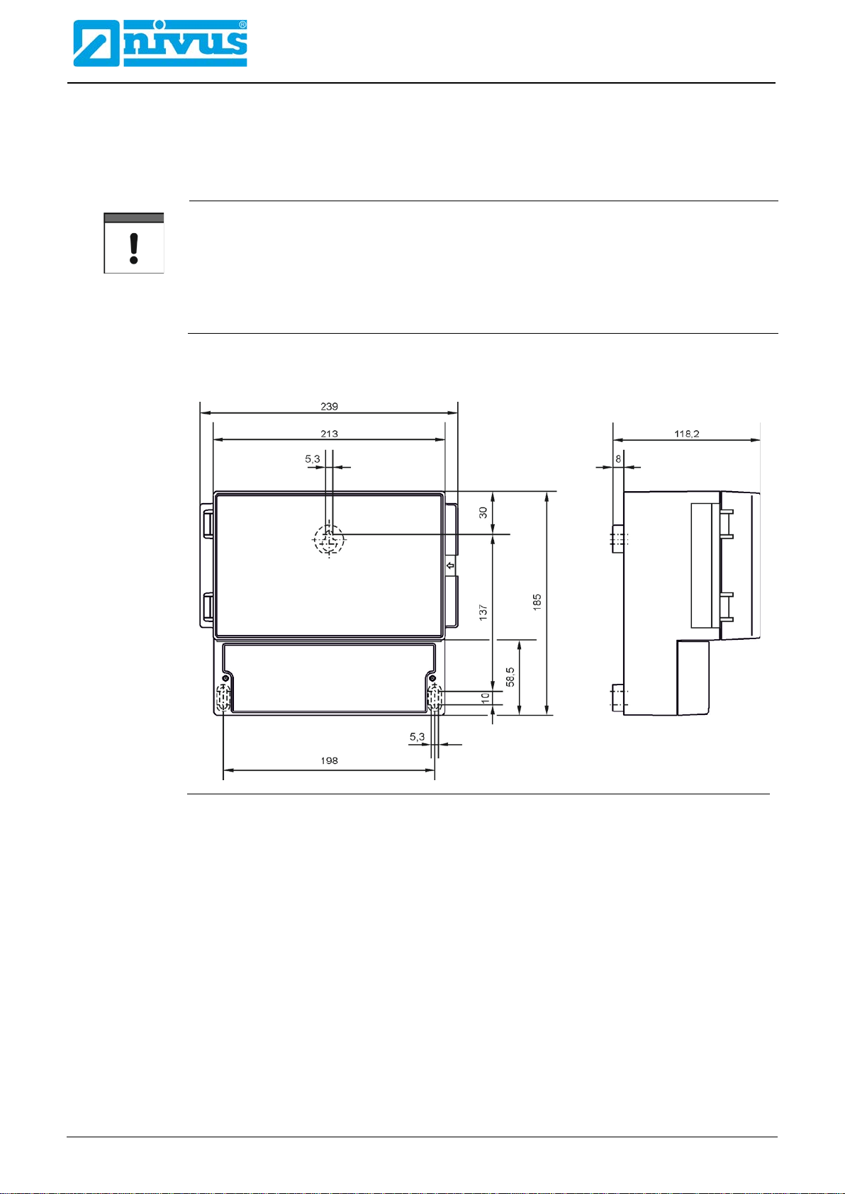
14.2 Enclosure Dimensions
Fig. 14-1 Wall Mount Enclosure
Table of contents
Other Nivus Transmitter manuals


Popular Transmitter manuals by other brands


Vertex
Vertex SignalTrans IST-P Installation and operation guide

SUPMEA
SUPMEA U-SUP-MP-C user manual

M-system
M-system VOS2T instruction manual

Emerson
Emerson ROSEMOUNT 5081-A instruction manual

Inovonics
Inovonics EN1223S EchoStream Installation and operation manual

Canon
Canon WFT-E7 Ver.2 instruction manual