Nivus NivuFlow 750 User manual

FLOW portable
Instruction Manual
Flow Measurement Transmitter
NivuFlow Mobile 750 / NivuFlow Mobile 750 Ex
Firmware Revision: 3.00
Revised manual
Document revision: 03 / 27.05.2020
Original Manual: German / rev. 03 as of 25.05.2020

Instruction Manual
NivuFlow Mobile 750
page 2 NFM 750 - rev. 03 / 27.05.2020
NIVUS AG, Switzerland
Burgstrasse 28
8750 Glarus, Switzerland
Phone +41 (0)55 6452066
Fax +41 (0)55 6452014
swiss@nivus.com
www.nivus.de
NIVUS Austria
Muehlbergstrasse 33B
3382 Loosdorf, Austria
Phone +43 (2754) 567 63 21
Fax +43 (2754) 567 63 20
www.nivus.de
NIVUS Sp. z o.o., Poland
ul. Hutnicza 3 / B-18
81-212 Gdynia, Poland
Phone +48 (0) 58 7602015
Fax +48 (0) 58 7602014
www.nivus.pl
NIVUS France
67870 Bischoffsheim, France
Phone +33 (0)3 88 9992 84
www.nivus.fr
NIVUS Ltd., United Kingdom
Wedgewood Rugby Road
Weston under Wetherley
Royal Leamington Spa
CV33 9BW, Warwickshire
Phone +44 (0)8445 3328 83
www.nivus.com
NIVUS Middle East (FZE)
Building Q 1-1 ap. 055
P.O. Box: 9217
Sharjah Airport International
Free Zone
Phone +971 6 55 78 224
Fax +971 6 55 78 225
middle-[email protected]
www.nivus.com
NIVUS Korea Co. Ltd.
#2502, M Dong, Technopark IT Center,
32 Song-do-gwa-hak-ro, Yeon-su-gu,
INCHEON, Korea 406-840
Phone +82 32 209 8588
Fax +82 32 209 8590
www.nivus.com
NIVUS Vietnam
21 Pho Duc Chinh, Ba Dinh,
Hanoi, Vietnam
Phone +84 12 0446 7724
www.nivus.com

Copyrights and property rights
NFM 750 - rev. 03 / 27.05.2020 page 3
Copyrights and property rights
This document and its contents are proprietary to NIVUS GmbH and are not to be repro-
duced or copied without the express written permission of NIVUS GmbH.
Violations oblige to compensation.
Important Note
This instruction manual may exclusively - even in parts - be copied or translated in any
other way with the express written consent of NIVUS GmbH.
Translation
If the device is sold to a country in the European Economic Area (EEA) this instruction manu-
al must be translated into the language of the country in which the device is to be used.
Should the translated text be unclear, the original instruction manual (German) must be con-
sulted or the NIVUS GmbH contacted for clarification.
Copyright
No part of this publication may be reproduced, transmitted, sold or disclosed without prior
permission. Damages will be claimed for violations. All rights reserved.
Names
The use of general descriptive names, trade names, trade-marks and the like in this manual
does not entitle the reader to assume they may be used freely by everyone. They are often
protected registered trademarks even if not marked as such.

Instruction Manual
NivuFlow Mobile 750
page 4 NFM 750 - rev. 03 / 27.05.2020
Document modifications
Rev.
Modifications
Editor in
charge
Date
03
Chap. “5 Warranty” added; chap. “19 Configuration/Device Types”
updated; chap. “23.1 Rechargeable Battery Pack”, “27 Connecting the
Connector Box for Inputs/Outputs” and “36.4.4 Digital Outputs” modified;
chap. “52.2 Power Adapter / Battery Charger” added; chap. “53
Dismantling/Disposal”: Note to EC WEEE-Directive updated; chap.
“Approvals and Certificates” updated; minor text and layout changes
MoG
27.05.2020
02
NIVUS France address modified; chap. “1.3.1 Colour code for wires and
single conductors”, “5 Liability disclaimer”, “22.1.3 Operation/Charging
via an Alternative Power Supply”, “24.2 Sensor Connection” modified;
chap. “24.3 Overvoltage Protection Measures” added; chap. “26
Connecting the Connector Box for Inputs/Outputs”: Fig. 26 2 modified;
chap. “29 Indication System of Status LED on NivuFlow Mobile”; chap.
“30 Setting Up Connection”: “Session Timeout” removed; chap. “31.3
Menus”: “Alert” added; chap. “35.4.1 Analog Inputs”, “37.2.3 Units”,
“37.2.4 Units Memory” and “38 Parameter Menu Communication”
modified; chap. “42 Parameter Menu Alert” added
MoG
17.04.2019
01
First version based on the German document
MoG
25.10.2018
00
---
---
---

Table of contents
NFM 750 - rev. 03 / 27.05.2020 page 5
Table of contents
Copyrights and property rights 3
Document modifications 4
Table of contents 5
General 10
1About this manual....................................................................................10
1.1 Applicable documentation...................................................................10
1.2 Signs and definitions used..................................................................10
1.3 Abbreviations used..............................................................................11
1.3.1 Colour code for wires and single conductors ...................................11
2Connections and Operating Elements ....................................................11
2.1 Power Supply......................................................................................11
2.1.1 Transmitter........................................................................................11
2.1.2 Rechargeable Batteries....................................................................12
2.2 NivuFlow Mobile Operating Elements.................................................12
2.3 Interfaces ............................................................................................13
Safety Instructions 14
3Used symbols and signal words..............................................................14
3.1 Valuation of the accident level............................................................14
3.2 Warning notices on the product (option).............................................15
4Safeguards and Precautions...................................................................15
5Warranty..................................................................................................16
6Liability disclaimer...................................................................................17
7Use in accordance with the requirements...............................................17
8Ex Protection...........................................................................................18
9User’s Responsibilities............................................................................19
10 Personnel requirements..........................................................................19
Delivery, Storage and Transport 20
11 Delivery ...................................................................................................20
12 Reception inspection...............................................................................20
13 Storage....................................................................................................21
14 Transport.................................................................................................21
15 Return......................................................................................................21
Product Specification 22
16 Product Construction and Overview........................................................22
16.1 Enclosure Dimensions ........................................................................23
16.2 Connectable Sensors/Devices............................................................23
17 Device identification ................................................................................24
18 Specifications..........................................................................................25
19 Configuration/Device Types....................................................................26

Instruction Manual
NivuFlow Mobile 750
page 6 NFM 750 - rev. 03 / 27.05.2020
Functional description 27
20 Operating Ranges...................................................................................27
21 Functional Principles...............................................................................27
21.1 Flow velocity measurement ................................................................27
21.1.1 Cross correlation ..............................................................................27
21.2 Level measurement.............................................................................29
21.2.1 2-wire level sensor............................................................................29
21.2.2 Water ultrasound ..............................................................................30
21.2.3 Air-ultrasound ...................................................................................30
21.2.4 Pressure ...........................................................................................31
Installation and Connection 32
22 General Information on Installation.........................................................32
22.1 Installation place .................................................................................32
22.2 Before Installation ...............................................................................32
22.2.1 PU stickers on enclosure frame .......................................................32
22.2.2 Gaskets.............................................................................................32
22.2.3 Securing the Instrument ...................................................................33
22.2.4 Connection Sockets..........................................................................33
23 Electrical Installation/Power Supply........................................................33
23.1 Rechargeable Battery Pack ................................................................34
23.1.1 Removing/Inserting the Rechargeable Battery Pack .......................34
23.1.2 Charging the rechargeable battery pack..........................................35
23.1.3 Operation/Charging via an Alternative Power Supply......................37
23.1.4 Operation/Charging with direct connection to mains power.............38
24 Sensor Installation in General.................................................................38
24.1 Sensor Installation Basics...................................................................38
25 Installation of Sensors.............................................................................39
25.1 Cable for Sensor Connection..............................................................39
25.2 Sensor Connection..............................................................................39
25.2.1 Connecting Sensors directly to NivuFlow Mobile.............................39
25.2.2 Connection of Flow Velocity Sensors using the Adapter Box..........40
25.3 Overvoltage Protection Measures.......................................................40
26 Single external Connection for Inputs/Outputs .......................................41
27 Connecting the Connector Box for Inputs/Outputs .................................41
28 (T-Shape) Antenna for GPRS Data Remote Transmission ....................43
Putting into Operation 44
29 Notes to Users.........................................................................................44
30 Indication System of Status LED on NivuFlow Mobile............................44
31 Setting Up Connection ............................................................................45
31.1 General................................................................................................45
31.2 Android Operating System..................................................................45
31.3 iOS Operating System ........................................................................48
31.4 Windows Operating System................................................................51
32 Menu Operation/Overview ......................................................................54
32.1 Display Overview ................................................................................54
32.2 Saving Parameters..............................................................................55
32.3 Menus..................................................................................................56

Table of contents
NFM 750 - rev. 03 / 27.05.2020 page 7
Parameter Setting 57
33 General Programming.............................................................................57
33.1 Save Parameters ................................................................................57
33.2 Change WLAN Password ...................................................................57
33.3 Change Instrument SSID....................................................................58
33.4 Lost Password.....................................................................................58
33.5 Automatic Data Transmission to USB Stick........................................59
34 Parameter Setting using Quick Start.......................................................59
35 Parameter Functions...............................................................................62
35.1 Main Menu ..........................................................................................62
35.2 Functions of the first Menu Level........................................................63
35.2.1 Menu - Application............................................................................63
35.2.2 Menu - Data......................................................................................64
35.2.3 Menu - System .................................................................................64
35.2.4 Menu - Communication ....................................................................65
35.2.5 Menu - Display..................................................................................65
35.2.6 Menu - Battery (12V) ........................................................................66
35.2.7 Menu – Quick Start...........................................................................67
35.2.8 Menu – Alert .....................................................................................68
36 Application Parameters Menu.................................................................69
36.1 Menu Measure Place..........................................................................69
36.1.1 Name of Measurement Place...........................................................69
36.1.2 Channel Profiles ...............................................................................69
36.1.3 Sludge Level.....................................................................................75
36.1.4 3D-View............................................................................................75
36.1.5 Low-Flow Suppression .....................................................................75
36.1.6 Damping ...........................................................................................76
36.1.7 Stability.............................................................................................77
36.2 Setting Parameters in Menu h-Sensors..............................................77
36.2.1 h-Sensor types .................................................................................77
36.2.2 Define Measuring Ranges................................................................79
36.3 Setting Parameters in Menu v-Sensors..............................................81
36.3.1 Number of Flow velocity sensors .....................................................81
36.3.2 Selecting the Sensor Types..............................................................82
36.3.3 Sensor mounting position.................................................................82
36.3.4 Weighting..........................................................................................86
36.3.5 v-Determination low levels................................................................87
36.3.6 Limitation of velocity evaluation........................................................89
36.4 Menu Inputs/Outputs (analog and digital)...........................................89
36.4.1 Analog Inputs....................................................................................90
36.4.2 Analog Outputs.................................................................................91
36.4.3 Digital Inputs.....................................................................................92
36.4.4 Digital Outputs..................................................................................93
36.5 Diagnostics Menu................................................................................95
37 Parameter Menu Data.............................................................................95
37.1 Trend...................................................................................................96
37.2 Day Totals...........................................................................................98
37.3 Data Memory.......................................................................................99

Instruction Manual
NivuFlow Mobile 750
page 8 NFM 750 - rev. 03 / 27.05.2020
38 System Parameter Menu ......................................................................102
38.1 Information ........................................................................................102
38.2 Region Settings.................................................................................102
38.2.1 (Operation) Language ....................................................................103
38.2.2 Date Format....................................................................................103
38.2.3 Units................................................................................................103
38.2.4 Units Memory .................................................................................104
38.3 Time/Date..........................................................................................105
38.4 Error Messages.................................................................................106
38.5 Service ..............................................................................................106
38.5.1 Service Level..................................................................................107
38.5.2 Restart............................................................................................107
38.5.3 Powerdown.....................................................................................107
38.5.4 Parameter Reset ............................................................................107
38.5.5 Update NivuFlow ............................................................................107
38.5.6 Update Bootloader..........................................................................107
38.6 Storage Mode....................................................................................107
39 Parameter Menu Communication .........................................................109
40 Parameter Menu Display.......................................................................114
41 Parameter Menu Battery (12V).............................................................115
42 Parameter Menu Quick Start.................................................................116
42.1 Menu >Quick Start< / >Region Settings< .........................................116
42.2 Menu >Quick Start< / >Measure Place<...........................................117
42.3 Menu >Quick Start< / >h-Sensors< ..................................................117
42.4 Menu >Quick Start< / >v-Sensor 1< .................................................118
43 Parameter Menu Alert...........................................................................118
43.1 Menu >Alert< / >Flow<......................................................................119
43.2 Menu >Alert< / >Level<.....................................................................120
43.1 Menu >Alert< / >Velocity<.................................................................120
43.1 Menu >Alert< / >Water temperature<...............................................121
43.1 Menu >Alert< / >Battery (12V)<........................................................122
43.1 Menu >Alert< / >Analog Input 1<......................................................123
43.1 Menu >Alert< / >Analog Input 2<......................................................123
43.1 Menu >Alert< / >Analog Input 3<......................................................124
43.1 Menu >Alert< / >Digital Input< ..........................................................125
Diagnostics 126
44 Diagnostics Menu Principles.................................................................126
45 Diagnostics Menu h-Sensors................................................................127
46 Diagnostics Menu v-Sensors ................................................................128
47 Diagnostics Menu Inputs and Outputs..................................................129
47.1 Important Information on the Simulation...........................................129
48 Diagnostics Menu Flow profile..............................................................130
49 Diagnostics Menu Signal Analysis........................................................131
50 Simulation..............................................................................................133

Table of contents
NFM 750 - rev. 03 / 27.05.2020 page 9
Maintenance and Cleaning 134
51 Maintenance..........................................................................................134
51.1 Maintenance Interval.........................................................................134
51.2 Customer Service Information ..........................................................135
52 Cleaning ................................................................................................135
52.1 Transmitter........................................................................................135
52.2 Power Adapter / Battery Charger......................................................135
52.3 Sensors.............................................................................................135
53 Dismantling/Disposal.............................................................................136
54 Installation of spare parts and parts subject to wear and tear ..............136
55 Accessories...........................................................................................136
Index 138
Credits and Licenses 140
56 List of references of the licenses and codes used................................140
Approvals and Certificates 141

Instruction Manual
NivuFlow Mobile 750
page 10 NFM 750 - rev. 03 / 27.05.2020
General
1 About this manual
Important note
READ CAREFULLY BEFORE USE.
KEEP IN A SAFE PLACE FOR LATER REFERENCE.
This instruction manual is for the intended use of the flow measurement transmitter NivuFlow
Mobile 750. This manual is oriented exclusively to qualified expert personnel.
Read this instruction manual carefully and completely prior to installation and connection
since it contains relevant information on this product. Observe the notes and particularly fol-
low the warning notes and safety instructions.
If you should have problems to understand information contained within this instruction man-
ual either contact the NIVUS GmbH or one of the distributors for further support. The legally
associated companies and subsidiaries of NIVUS group cannot be held responsible for dam-
age to persons or material due to incorrectly understood information in this instruction.
1.1 Applicable documentation
For the installation and operation of the complete system extra instruction manuals or tech-
nical descriptions may be required apart from this manual.
•Technical Instruction for Correlation Sensors and external Electronic Box
•Installation Instruction for Correlation and Doppler Sensors
These manuals are provided with the auxiliary units or sensors and/or are available as down-
load on the NIVUS homepage.
1.2 Signs and definitions used
Image
Meaning
Remark
(Action) Step
Action to be performed by you.
Note the numbering of action steps. Observe the
order of the working steps.
Cross-reference
Refers to further or detailed information.
>Text<
Parameter or Menu
Indicates a parameter or a menu that is selected
or described.
Reference to document
Refers to an accompanying documentation.
Table 1 Structural elements within the manual

General
NFM 750 - rev. 03 / 27.05.2020 page 11
1.3 Abbreviations used
1.3.1 Colour code for wires and single conductors
The abbreviations of colours, wire and components follow the international colour code ac-
cording IEC 60757.
BK black BN brown RD red
OG orange YE yellow GN green
BU blue VT violet GY grey
WH white PK pink TQ turquoise
GNYE green/yellow GD gold SR silver
2 Connections and Operating Elements
2.1 Power Supply
2.1.1 Transmitter
The NivuFlow Mobile (Fig. 2-1 no. 1) is supplied by rechargeable battery packs. Once
plugged in the batteries are connected to the transmitter via the charging pins (Fig. 2-1 no. 4)
supplying the required operating voltage.
1 Transmitter
2 Battery compartment (two battery packs; illustration without batteries)
3 Guide pins for battery packs
4 Charging pins for AC power supply of transmitter
5 USB-A interface
Fig. 2-1 Power supply by battery packs (top view)
Instruction Manual
NivuFlow Mobile 750
page 12 NFM 750 - rev. 03 / 27.05.2020
2.1.2 Rechargeable Batteries
The rechargeable batteries can be charged either in installed condition or while removed by
using a battery charger (optional accessory).
WARNING Risk of explosion when charging battery packs in Ex areas
Charge rechargeable battery packs outside of Ex areas only.
Do not charge within Ex areas.
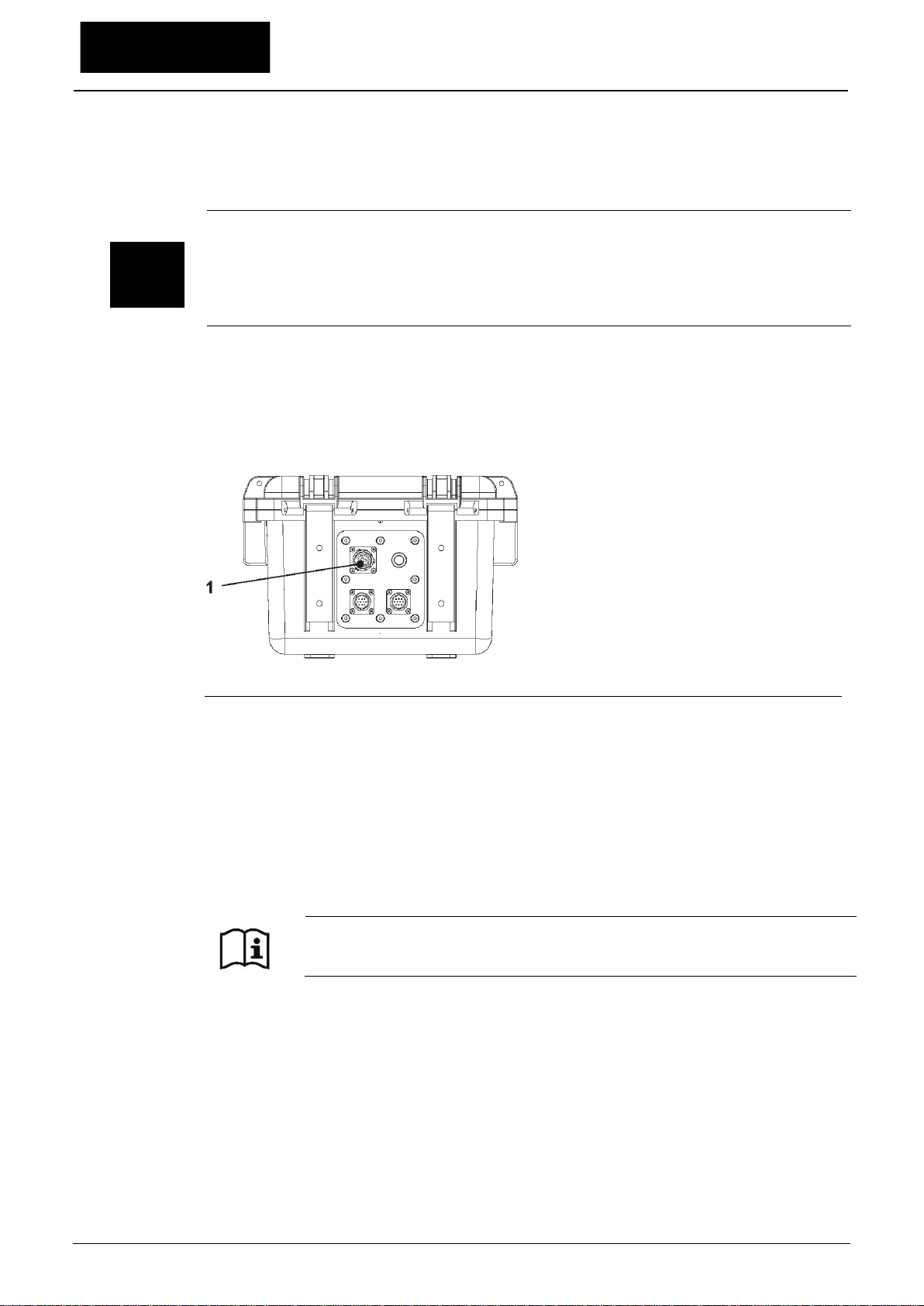
There are two different options to charge the batteries while being installed:
•Power adapter 110...230 V AC using the multifunction socket (Fig. 2-2 no. 1) on the re-
verse side of the enclosure
•External power source 12...14 V DC (e.g. battery, solar module, fuel cell etc.) using ca-
ble via multifunction socket
1 Multifunction socket
Fig. 2-2 Charging batteries via multifunction socket
Sensor wiring diagrams can be found in chapter “25 Installation of Sensors”.
2.2 NivuFlow Mobile Operating Elements
NivuFlow Mobile itself has no direct operating elements. Instrument operation and the setting
of parameters are carried out completely by using smartphone, tablet, notebook and PC.
Use here the PC mouse or the touchscreen.
Also refer to the instruction manuals of your preferred smartphone, tablet,
notebook or PC.

General
NFM 750 - rev. 03 / 27.05.2020 page 13
2.3 Interfaces
The transmitter is equipped with various interfaces which can be found on the reverse side or
on the top of the instrument.
1 Sensor socket v2/h
2 Multifunction socket I/O
3 Sensor socket v1
4 USB-A interface (accessible with open cover)
5 GPRS SIM card slot (in connection with GPRS antenna)
Fig. 2-3 Available interfaces

Instruction Manual
NivuFlow Mobile 750
page 14 NFM 750 - rev. 03 / 27.05.2020
Safety Instructions
3 Used symbols and signal words
3.1 Valuation of the accident level
The general warning symbol indicates the risk of personal injuries or death. In the text sec-
tion the general warning symbol is used in conjunction with the signal words described
below.
DANGER Warnings in high degree of risk
Indicates a high-risk, imminently hazardous situation which will result in death or serious
injury if not avoided.
WARNING Warnings in medium degree of risk
Indicates a possible danger with medium risk which may result in a life-threatening situa-
tion or (severe) bodily injury if it is not avoided.
CAUTION
Warnings in low-risk or property damages
Indicates a possible danger with moderate risk which may result in minor or moderate per-
sonal injury or material damage if not avoided.
WARNING Danger by electric voltage
Indicates a hazard with a high risk of electric shock which may result in a life-threatening
situation or (severe) bodily injury if it is not avoided.
Important Note
Contains information that should be highlighted.
Indicates a potentially damaging situation which can result in a damage of the product or an
object in its environment.
Note
Contains information and facts.

Safety Instructions
NFM 750 - rev. 03 / 27.05.2020 page 15
3.2 Warning notices on the product (option)
General warning label
This symbol is for operators to refer to this instruction manual.
Observing the information contained therein is required in order to maintain protection
measures provided by the instrument during installation procedures and operation.
Protective conductor
This symbol refers to the protective conductor of the unit.
Depending on the mode of installation the instrument shall be operated solely connected to
an appropriate protective conductor according to applicable laws and regulations.
4 Safeguards and Precautions
Working with NIVUS instruments requires to observe and to follow the safety
measures and precautions below generally and at any time. These notes and warnings
will not be repeated for each description within the document.
WARNING Check danger through explosive gases
Prior to beginning mounting, installation and maintenance make sure to observe any regu-
lations on safety at work as well as to check the potential risk due to explosive gases. Use
a gas warner to check.
When working in the channel system make sure to avoid electrostatic charge:
Avoid unnecessary movements to minimise the risk of static energy accumulating.
Discharge any possible static electricity from your body before you begin to install
sensors.
Disregarding may lead to personal injury or damage your equipment.

Instruction Manual
NivuFlow Mobile 750
page 16 NFM 750 - rev. 03 / 27.05.2020
WARNING Germ contamination
Please note that due to the operation in the waste water field the measurement system and
cables may be loaded with dangerous disease germs. Respective precautionary measures
must be taken to avoid damage to one’s health.
Wear protective clothing.
WARNING Observe occupational safety regulations
Before starting installation work, observing the work safety regulations need to be checked.
Disregarding may lead in personal injury.
WARNING Do not disable safety devices
It is strictly prohibited to disable the safety devices or to change the way they work.
Disregarding may lead in personal injury.
WARNING
Disconnect the systems from mains
Maintenance, cleaning and/or repairs (by qualified personnel only) may only be performed
when de-energised.
Disregarding may lead to electric shocks.
Putting into operation by trained experts only
The entire measurement system shall be installed and put into operation by trained expert
personnel only.
Integrated buffer battery
The exchange of the integrated buffer battery shall be carried out by NIVUS staff or per-
sonnel authorised by NIVUS only. Otherwise the guarantee expires.
5 Warranty
The device has been functionally tested before delivery. If it is used as intended (see chapter
“7 Use in accordance with the requirements”) and the operating instructions, the applicable
documents (see chapter “1.1 Applicable documentation”) and the safety notes and instruc-
tions contained therein, are observed, no functional restrictions are to be expected and per-
fect operation should be possible.
Please also note in this regard the next chapter “6 Liability disclaimer”.
Limitation of warranty
In the event of non-compliance with the safety instructions and instructions in this docu-
ment, the companies of the NIVUS group of companies reserve the right to limit the
warranty.

Safety Instructions
NFM 750 - rev. 03 / 27.05.2020 page 17
6 Liability disclaimer
The legally associated companies and subsidiaries of NIVUS group assume no liability
•for damages owing to a change of this document. The legally associated companies
and subsidiaries of the NIVUS group reserve the right to change the contents of this
document and this disclaimer at any time and without any notice.
•for damages to persons or objects resulting from failure to comply with applicable
regulations. For connection, commissioning and operation of the sensors all available
information and higher local legal regulations (in Germany e.g. VDE regulations) such
as applicable Ex regulations as well as safety requirements and regulations in order to
avoid accidents shall be adhered to.
•for damages to persons or objects resulting from improper use. For safety and warran-
ty reasons, all internal work on the instruments beyond from that involved in normal in-
stallation and connection, must be carried out only by qualified NIVUS personnel or
persons or companies authorised by NIVUS.
•for damages to persons or objects resulting from the use of instruments in technically
imperfect condition.
•for damages to persons or objects resulting from the use of instruments not in accord-
ance with the requirements.
•for damages to persons or objects resulting from failure to comply with safety infor-
mation contained within this instruction manual.
•for missing or incorrect measurement values or resulting consequential damages due to
improper installation.
7 Use in accordance with the requirements
Note
The instrument is intended solely for the purpose described below. Modifying or using the
instruments for any other purposes without the written consent of the legally associated
companies and/or subsidiaries of NIVUS group will not be considered as use in accordance
with the requirements.
The legally associated companies and subsidiaries of NIVUS group cannot be held respon-
sible for any damage resulting from improper use.
The user alone bears any risk.
The NivuFlow Mobile 750 transmitter incl. the accompanying sensors is designed for tempo-
rary flow measurement of slight to heavily polluted aqueous liquids for open channels and
part filled and full pipes.
NivuFlow Mobile 750 is designed and manufactured in accordance with the current state of
the art and with the recognised safety rules and regulations applicable at the time this docu-
ment is issued. Danger to persons or material damage cannot be completely ruled out, how-
ever.
The maximum permissible limit values as specified in chapter “18 Specifications” shall be
necessarily observed. Any case varying from these conditions which is not approved by
NIVUS GmbH in written form is left at the owner’s risk.

Instruction Manual
NivuFlow Mobile 750
page 18 NFM 750 - rev. 03 / 27.05.2020
8 Ex Protection
The portable transmitter NivuFlow Mobile 750 and the accompanying sensors are designed
to be used in areas with explosive atmospheres (zone 1).
The following conditions must be observed:
•Programming the unit under Ex conditions is permissible:
with the programming person within the Ex area as soon as the indicator and
operating unit used has an Ex approval
with the programming person outside of the Ex area as soon as the indicator
and operating unit used has no Ex approval
•Maintenance and repairs shall be executed only outside of Ex area
•Rechargeable batteries shall be removed/inserted and charged only outside of
Ex areas
•In general, only rechargeable batteries approved by NIVUS shall be used within
Ex areas
•Use the USB interface only outside of Ex areas
•Replace the SIM card only outside of Ex areas
•The instrument shall be (after successful installation at the measurement place) se-
cured against unauthorised opening by using a padlock (holes on the side of the enclo-
sure)
Approval
Transmitter
II 2G Ex eb ib [ib] mb IIB T4 Gb (TÜV 17 ATEX 196722 X)
Sensors
II 2G Ex ib IIB T4 Gb (TÜV 12 ATEX 087812)
Validity of Ex Approval
The Ex approval is only valid in connection with the respective indication on the transmitter
or the sensor nameplate.
Declarations of Conformity and Test Reports
For installation and commissioning the EC Declarations of Conformity and Test Reports of
the respective authorities shall be strictly followed.
Ex Approval for Sensors
The Ex approval for the sensors is part of the Technical Description for Cross Correlation
and Doppler Sensors.

Safety Instructions
NFM 750 - rev. 03 / 27.05.2020 page 19
9 User’s Responsibilities
Important Note
In the EEA (European Economic Area) national implementation of the framework directive
89/391/EEC and corresponding individual directives, in particular the directive 2009/104/EC
concerning the minimum safety and health requirements for the use of work equipment by
workers at work, as amended, are to be observed and adhered to.
In Germany e g. the Industrial Safety Ordinance must be observed.
Make sure to have a local operating permit available and observe the associated conditions.
In addition to this you must observe environmental requirements and local laws on the follow-
ing points:
•Personnel safety (accident prevention regulations)
•Safety of work materials and tools (safety equipment and maintenance)
•Disposal of products (laws on wastes)
•Disposal of materials (laws on wastes)
•Cleaning (cleansing agents and disposal)
Connections
Operators shall make sure prior to operating the instrument that during installation and initial
start-up the local regulations (such as regulations for electrical connection) are observed.
Keep the manual
Keep this manual in a safe place and make sure it is available for the users of this product at
any time.
Provide the manual
In case of selling the instrument this instruction manual shall be provided to the purchaser
since it is a part of the standard delivery.
10 Personnel requirements
Installation, commissioning and maintenance shall be executed only by personnel meeting
the demands as follows:
•Expert personnel with relevant training and appropriate qualification
•Personnel authorised by the plant operator
Qualified personnel
within the context of this documentation or the safety notes on the product itself are per-
sons who are sufficiently familiar with installation, mounting, starting up and operation of
the product and who have the relevant qualifications for their work; for example:
I. Training, instruction or authorisation to activate/deactivate, isolate, ground, and
mark electric circuits and devices/systems according to the safety engineering
standards.
II. Education and instruction according to the standards of safety engineering regard-
ing the maintenance and use of adequate safety equipment.
III. First aid training

Instruction Manual
NivuFlow Mobile 750
page 20 NFM 750 - rev. 03 / 27.05.2020
Delivery, Storage and Transport
11 Delivery
The standard delivery of the NivuFlow Mobile 750 basically contains:
•Transmitter type NivuFlow Mobile 750 (according to shipping documents)
•Ring magnet (solenoid)
•USB stick
•Screw driver for hexagon socket screws
•PU stickers (two pieces: 31x17x3.5 mm) to avoid vacuum in the enclosure in case of
being returned (via airfreight) to NIVUS (e.g. for maintenance)
•T-shape antenna (only for versions with internal GPRS / UMTS / LTE modem)
•Padlock (only for Ex versions)
•Instruction manual (incl. certificate(s) of conformity) containing any relevant information
on how to operate the NivuFlow
Check extra accessories depending on your order and by using the delivery note.
12 Reception inspection
Check the packaging for visible damage immediately after receipt. Any possible damage in
transit shall be instantly reported to the carrier. Furthermore a written report shall be sent to
NIVUS GmbH in Eppingen.
Incomplete deliveries shall be reported in writing either to your local representative or directly
to the NIVUS head office in Eppingen within two weeks.
Important note
Mistakes cannot be rectified later!
Prior to the first use:
1. Open enclosure cover.
2. Remove both PU stickers (two pieces; 31x17x3.5 mm), if available, from the left
and right enclosure frame (Fig. 15-1 no. 1). The stickers have been attached
prior to shipping (via airfreight) to prevent the enclosure from getting closed and
to avoid vacuum formation due to extreme temperature changes during ship-
ping.
Other manuals for NivuFlow 750
1
This manual suits for next models
1
Table of contents
Other Nivus Transmitter manuals


Popular Transmitter manuals by other brands


National Wireless
National Wireless Securetek ST-100 Series Installation and User Instruction

API
API DuoPak APD 2035 instructions

Evikon
Evikon PluraSens E2638-VOC user manual

Amphony
Amphony RX1 User and installation guide

Nautel
Nautel XL12 Technical instructions

Endress+Hauser
Endress+Hauser Liquisys CUM 252 operating instructions