manuals.online logo
Brands
  1. Home
  2. •
  3. Brands
  4. •
  5. Njoy
  6. •
  7. Power Supply
  8. •
  9. Njoy Garun Series User manual

Njoy Garun Series User manual

Garun Series
Installaon and baery connecon for 40 pieces EBM,
sequence (10+10 x 2)
40 pieces baery cabinet UPBPTA1222AX-AZ01B
Before using this product, carefully read all product documentaon and retain it for future reference.
150.1
2 3
Garun Series models that are compable with this EBM model:
10K VA Garun 10KL
Installation and battery connection in sequence (10 + 10) x 21
Step 1
Turn the cabinet’s switch to OFF.
Remove the top lid by sliding
itupwards.
Step 2
Remove the left-side pieces
that help keep the batteries in
place.
Front
of the
cabinet
Front
of the
cabinet
Left side view
Left side view
Thank you for purchasing our products!
Please read this manual before using the product.
Focusing on quality at compeve prices, nJoy designs
consumer products for a beer and enjoyable way into
the digital world.
The baery pack is a product that works only with an UPS.
The baery pack will provide or extend the backup me of
your UPS.
4 5
Step 3
Identify the placement of
trays in the battery cabinet,
existing on three levels:
down, middle and top. Put
the batteries on the trays,
starting with the bottom
tray, then the middle one
and the top one at last.
The trays will contain, from
bottom up: 14 batteries
(down), 14 batteries (middle),
12 batteries (top), total 40
batteries.
4.2 Then, on the same
tray, place another 7
batteries upwards, with the
terminals down, this time
with the terminals towards
the left of the cabinet.
Step 4
Looking at the front of the
cabinet, the batteries will be
placed upwards:
4.1 First, on the lower
(down) tray, through the
left side, place 7 batteries
through to the right side
of cabinet, seated with
terminals down, towards
outside the cabinet.
4.3 Populate middle
tray with batteries, sitting
upright, first row of 7
batteries with terminals
towards the right of the
cabinet, but this time placed
with the terminals up (as
opposed to the tray below).
4.4 Continue populating
the middle tray with another
7 batteries, placed upwards,
with terminals up and
towards the left side of the
cabinet.
4.5 Top tray is populated
with 12 batteries placed
with terminals similar with
the bottom tray.
Right side view
Front
of the
cabinet
Front
of the
cabinet
Front
of the
cabinet
Front
of the
cabinet
Left side viewLeft side view
Left side view
Down
Middle
To p
6 7
Step 5
Insert back the pieces that
hold the batteries in place.
Step 6
Find the connection cables. Each cable is numbered from 1 to 7, with the
following quantities for each cable type:
Step 7
The following connections are made (according to the diagram on pages 8-9).
In the diagram each battery is coded according to tray level, side and number.
For example. DR2 means battery no. two (counting from the front of the
cabinet), from the Down tray, Right side of the cabinet:
7.1 Using cables no.1, connect all batteries on the 3 levels in series
((-, black) terminal of the first battery to the (+, red) terminal of the adjacent
battery), except for two batteries on the middle level, namely: MR3 and MR4,
respectively ML3 and ML4, which will be connected as shown in the step 7.6.
7.2 Using cables no.2 connect the free terminals of the ML7 batteries
with UL6, respectively, MR7 with UR6.
7.3 Using the cables no. 3, connect the free terminals of the DL1 batteries
with ML1, respectively MR1 with DR1.
7.4 Using one of the red no. 4 cables, bound to the cabinet, connect the
free (+, red) terminal of the DR7 battery on the right side of the cabinet. The
other red cable no. 4, bound to the cabinet, connect it to the free (+, red)
terminal of UL1 battery on the left side of the cabinet.
7.5 Using one of the no. 5, black cables, bounded to the cabinet, connect
the free (-, black) terminal of the UR1 battery on the right side of the cabinet.
The other black no. 5 cable, bounded to the cabinet, connect it to the free
(-, black) terminal of the DL7 battery on the left side of the cabinet.
7.6 Using the two blue short cables no.7, with one of the branch provided
with double connector, connect the free terminals of ML3 and ML4 batteries
on the left side, respectively MR3 and MR4 batteries on the right side. Then
connect the free terminals to one of the blue cables no. 6, bounded to the
cabinet (one on each side of the cabinet).
Nr. Descripon Pieces Cable numbering
1 #10 AWG cable (Black) 32 1
2 #10 AWG cable (Black) 2 2
3 #10 AWG cable (Black) 2 3
4 #10 AWG cable (Red) - bound to the cabinet 2 4 (BAT+)
5 #10 AWG cable (Black) - bound to the cabinet 2 5 (BAT-)
6 #10 AWG cable (Blue) - bound to the cabinet 2 6 (N)
7 #10 AWG cable (Blue) 2 7
Cable numbering
Front
of the
cabinet
Left side view
8 9
MR6MR7 MR5 MR4 MR3 MR2 MR1
1 1 1 1 1
DR6DR7 DR5 DR4 DR3 DR2 DR1
11 11 11
UR6 UR5 UR4 UR3 UR2 UR1
1 1 1 1 1
7
2
4
+-
N+-
N
DL2DL1 DL3 DL4 DL5 DL6 DL7
11 11 11
UL1 UL2 UL3 UL4 UL5 UL6
1 1 1 1 1
ML2ML1 ML3 ML4 ML5 ML6 ML7
1 1 1
7
1 1
3
2
5
Top
Front of the cabinet
Switch
Right side view Bottom
6
6
6
The second set of cables 5, 4 și 6 connect on the left side The second set of cables 5, 4 și 6 connect on the right side
5 5
4
4
Left side view
Top
Front of the cabinet
Switch
Bottom
5
4
6
3
10 11
Step 8
Make sure the cables are
correctly connected on each
side.
Right side view
Front
of the
cabinet
Front
of the
cabinet
Left side view
8.1
Slide the top lid back on and
secure it in place.
Step 9
Switch the power to ON. The EBM is now active and functioning.
Front
of the
cabinet
Left side view
NOTE!
If you want to use only one battery string (10 + 10) x1, please populate
with batteries only the bottom tray (JD1-JD7 batteries on the right side,
respectively JS1-JS7 on the left side). In the middle, just put the batteries
from MD1 to MD3 on the right side, respectively MS1 - MS3 on the left side.
Follow the same steps for connecting the cables. Will you use only a black
cable, one red cable and the two blue cables bounded to the cabinet. Please
connect the blue cables bounded to the cabinet to MR3 (-, black) battery
terminal on the right side, respectively ML3 (+, red) terminal on the left side
(you will no longer use the short blue cables no. 7).
Memo
Disposal of Old Electrical & Electronic Equipment
(Applicable in the European Union and other European countries with
separate collecon systems)
This symbol on the product or on its packaging indicates that this product shall
not be treated as household waste.
Instead it shall be handed over to the applicable collecon point for the recycling
of electrical and electronic equipment.
By ensuring this product is disposed of correctly, you will help prevent potenal
negave consequences for the environment and human health, which could
otherwise be caused by inappropriate waste handling of this product.
The recycling of materials will help to conserve natural resources.

Other manuals for Garun Series

3

This manual suits for next models

1

Other Njoy Power Supply manuals

Njoy Freya Series User manual

Njoy

Njoy Freya Series User manual

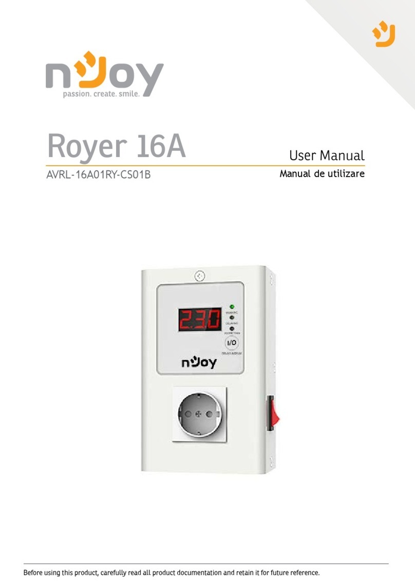
Njoy Royer 16A User manual

Njoy

Njoy Royer 16A User manual

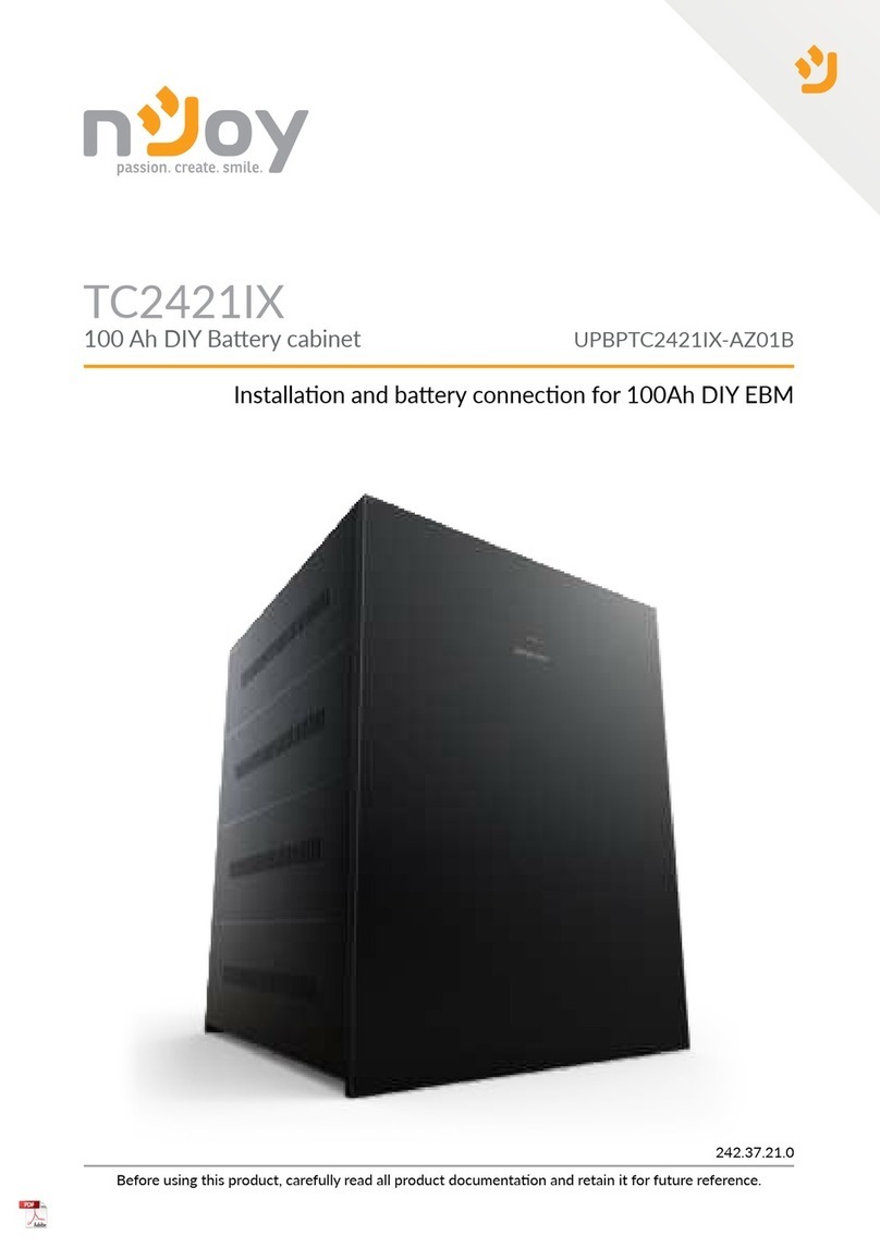
Njoy TC2421IX User manual

Njoy

Njoy TC2421IX User manual

Njoy cStation 600 User manual

Njoy

Njoy cStation 600 User manual

Njoy Titan Series User manual

Njoy

Njoy Titan Series User manual

Njoy Storm Series User manual

Njoy

Njoy Storm Series User manual

Njoy PWPS-065A04W-BU01B User manual

Njoy

Njoy PWPS-065A04W-BU01B User manual

Njoy Legion 600 User manual

Njoy

Njoy Legion 600 User manual

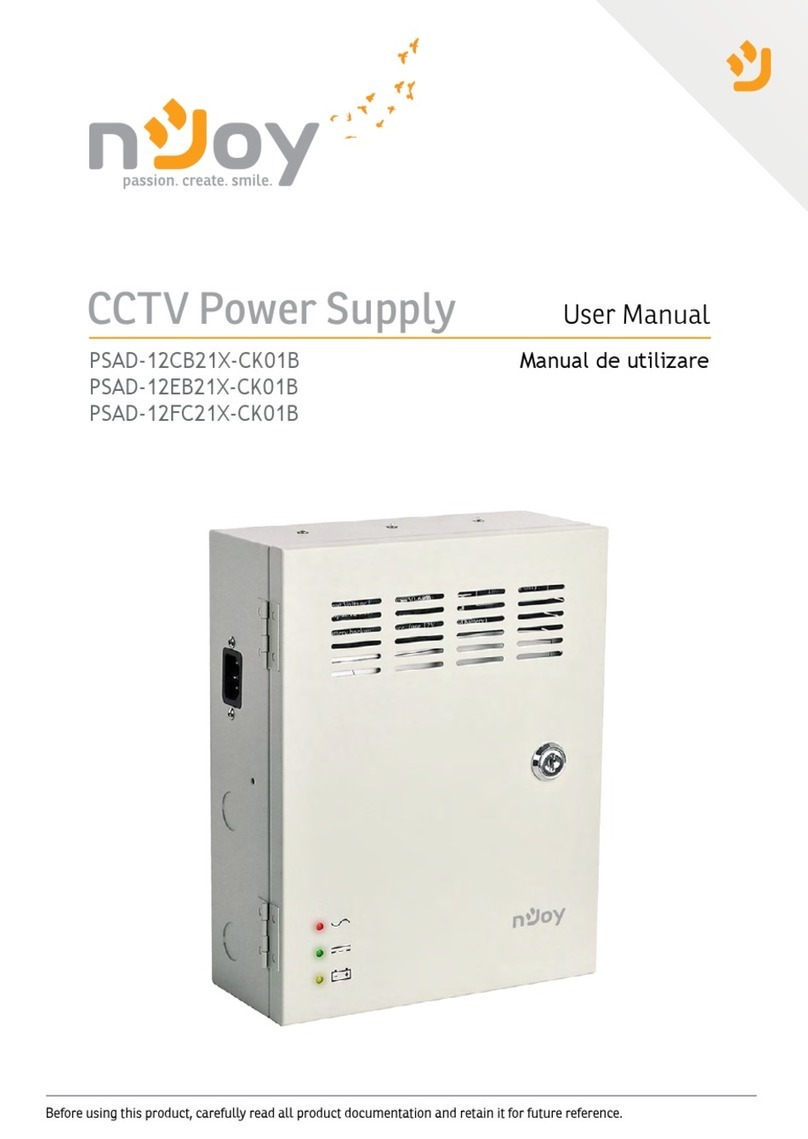
Njoy PSAD-12CB21X-CK01B User manual

Njoy

Njoy PSAD-12CB21X-CK01B User manual

Njoy Garun Series User manual

Njoy

Njoy Garun Series User manual

Popular Power Supply manuals by other brands

Nice PS 224 Instructions and warnings for the fitter

Nice

Nice PS 224 Instructions and warnings for the fitter

Antec HCG-520 user manual

Antec

Antec HCG-520 user manual

Pulsar EN54-5A17LCD manual

Pulsar

Pulsar EN54-5A17LCD manual

Velleman LABPS1503U user manual

Velleman

Velleman LABPS1503U user manual

GW Instek PSU Series user manual

GW Instek

GW Instek PSU Series user manual

NewMar EP 12-10 manual

NewMar

NewMar EP 12-10 manual

Monerator Gusto 10 user manual

Monerator

Monerator Gusto 10 user manual

SoundCraft DPS-3 User guide and technical manual

SoundCraft

SoundCraft DPS-3 User guide and technical manual

bonitron M3628ACF Customer Reference Manual

bonitron

bonitron M3628ACF Customer Reference Manual

Elektro-Automatik PSI 8000 2U manual

Elektro-Automatik

Elektro-Automatik PSI 8000 2U manual

Alarmtech PSV 2435-40 instruction manual

Alarmtech

Alarmtech PSV 2435-40 instruction manual

Alcatel OmniAccess 6000 installation instructions

Alcatel

Alcatel OmniAccess 6000 installation instructions

PPA SS 400 CR manual

PPA

PPA SS 400 CR manual

ABB CP-E Series Operating and installation instructions

ABB

ABB CP-E Series Operating and installation instructions

Strong International XENON FXPS instruction manual

Strong International

Strong International XENON FXPS instruction manual

IAI PSA-24 instruction manual

IAI

IAI PSA-24 instruction manual

Rauckman Utility Products ZAPshield Application guide

Rauckman Utility Products

Rauckman Utility Products ZAPshield Application guide

Delta Elektronika SM15K Series manual

Delta Elektronika

Delta Elektronika SM15K Series manual

manuals.online logo
manuals.online logoBrands
  • About & Mission
  • Contact us
  • Privacy Policy
  • Terms and Conditions

Copyright 2025 Manuals.Online. All Rights Reserved.