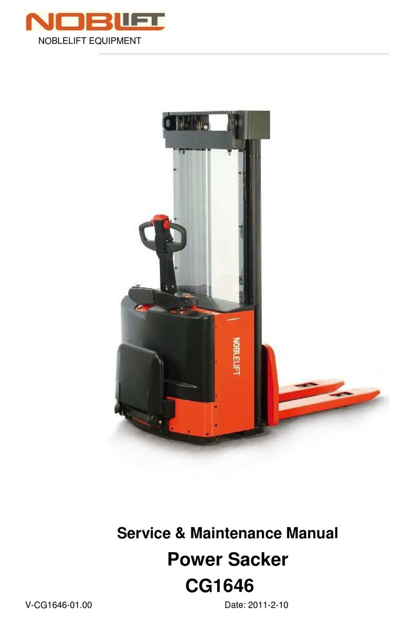
Noblelift MES150 User manual

Contents
1. Contents …………………………………………………………………………………1
2. Technical features of MES150 …………………………………………………………1
3. Adhesive of MES150…………………………………………………………………….1
4. Working norms for the operator………………………………………………………..2
The two functions of the brakes…………………………………………………….2
The forward/backward/swivel of the stacker………………………………………2
Lifting and lowering of the forks…………………………………………………....2
Load of the stacker…………………………………………………………………..2
The steps of unloading the goods……………………………………………………2
5. Recharge of Battery………………………………………………………………………3
6. Daily Maintenance Battery………………………………………………………………3
7. Programmed Maintenance………………………………………………………………3
8. Spare parts of the lifting parts…………………………………………………………..4
9. spare parts of the forks…………………………………………………………………..4
10. Circuit diagram of the MEC200…………………………………………………………4

1. TECHNICAL FEATURES
MODEL MES150
Capacity Kg 150
Lifting height(h1) mm 1550
Min .fork height mm 130
Fork width mm 330/520
Wheels Q’ty N 4
Lifting speed m/s Without load 83mm/s, with full load 70mm/s
Lowering speed m/s Without load 85mm/s, with full load 101mm/s
Battery 7 Ah/12v
Front wheel mm Φ75*32
Rear wheel mm Φ100*32
Transmission By belt and gear
Weight kg 58
Dimension (mm) X 500
Y 830
Z 1870
Z1 140
Z2 1540
X1 520
Y1 460
2. ADHESIVE
REMARKS:
A: Capacity limitation.
B: Warning.
C: Danger! “watch your step”.
D: Trademark
E: Switch
F: Recharging
G: Power
3. ADVISES
Read this instruction carefully before using the stacker. If necessary, please call our technical
people for assistance.
Move the stacker always keeping the forks at the lowest position while no loading on the
forks. Pay attention not to hurt anybody around your working area.
People are forbidden to stand on the forks of the stacker. Do not leave the stacker on the
working place after used. The load capacity of the stacker depends on the lifting height and the
position of the load center, please refer to the relative technical features in this instruction.

The adhesive label on the stacker must be always legible. Do not use the stacker for purpose
except lifting or lowering load.
Do not make casual repair. If repaired by unprofessional people, the safety modulus of the
machine could be altered. In case damage happens, repair it in the local place according to the
instruction or contact to us.
Carry out all the work and maintenance according to the norms after using it.
4. WORKING NORMS FOR THE OPERATOR
Do not worry about how to operating this stacker, the characteristic of this stacker is facility and
easy to operate.
The two function of the brakes
The rear wheels are equipped with brakes which with two functions, it can control the moving
of forward and backward effectively。Step the pedal of the brake backward, the stacker will be
braked. Step the pedal of the brake forward, the stacker will travel normally. The stacker
should be braked under the condition as following: A, stop at the slope; B, during charging; C,
when loading; D, leave unused.
The forward/backward/swivel of the stacker
Open the brake of the rear wheels, leave the two wheels at the state which can swivel freely.
Take hold of the armrest, push the stacker ahead, the stacker can move ahead. In the same way,
pull the stacker backward, the stacker will fall back. We use universal wheels on this truck, so
it’s very easy to swivel and swivel into any direction. It’s only need a small space because it
can be freely swiveled at the original position. If one of the brake is locked, the stacker will be
swiveled on an even keel according to the centre of a circle.
Lifting and lowering of the forks
Press the button of power to “ON”, then press the “ ” or “ ” to control the lifting
and lowering of the stacker. (Attention: Before lifting or lowering the forks with load on the
forks, please lock the rear wheels of the stacker to avoid moving of the stacker during
lowering and lowering.)
Load of the stacker
According to the deferent goods, this stacker can use the three kinds of shelves as double
forks, single fork, and platform. The ways of how to use these shelves are as follows:
A. Double forks ( be fitted for lifting the common load)
(1) Drive close to the load.
(2) Lift the forks below the load.
(3) Drive forward, bringing the forks under the load.
(4) Lift the load to get the load.
(5) Back the stacker with the load to make the descent if possible.
(6) Lower the load slowly.
B. Single fork (be fitted for lifting the cylindraceous load)
(1) Drive close to the load.
(2) Drive the fork to the centre of the circle of the load.
(3) Drive forward, extend the fork inside the cylinder.
(4) Lift the load to get the load.
(5) Back the stacker with the load to make the descent if possible.

(6) Lower the load slowly.
C. Platform (be fitted for the lifting the load with small volume)
(1) Drive close to the load.
(2) Lift the platform to a proper position (be convenient for people to stack the goods)
(3) Transfer the goods to the platform artificially.
(4) Lower the platform.
Attention: If possible, the platform with load can be lifted as the double forks.
The steps of unloading the goods
A. Double forks/ single forks
(1) Get close to the position.
(2) Lift the load up to the desired height position.
(3) Advance slowly to bring the load to the proper position.
(4) Lower the load to make the bottom of the forks on the shelf.
(5) After unloaded, back the forks slowly.
B.Platform
(1)Drive the stacker with load to the destination, and lock the rear wheels.
(2)Lift the platform to a proper height for people to unload it.
(3)Unloading.
5. RECHARGE OF BATTERY
The batteries of the stacker must be recharged with a constant continuity, and the recharging
should be very timely.
When recharging, switch off the power. Connect the charger to the power supply, and insert
the plug of the charger into the recharging faucet of the stacker, press the switch of charger,
recharging will begin. When recharging is over, the charger will stop automatically.
6. DAILY MAINTENANCE
The daily maintenance is a responsibility of the operator of the stacker. The main functions
that must been checked are as follows:
1 Check the retarder of the motor.
2 Check the forks.
3 Check the swivel wheel.
4 Check the transmission belt.
5 Check the charger.

7. PROGRAMMED MAINTENANCE
In the following we show a table in which there are some tips about the programmed
maintenance done by the authorized operators.
Before starting the maintenance you have to:
1. Put the stacker on an even and solid surface.
2. Brake the both rear wheels.
1 Check electrical systems, cleaning with air or with a brush and special detergent
2 Check the connections of the conductors.
3 Check and clean the driving-wheel group.
4 Check the wear of rollers and wheels.
5 Check movements and wears between masts and rollers with bearings.
6 Check and tighten all the screws and nuts.
7 Complete greasing of the stacker, bearings and sliding masts.
SPARE PARTS OF THE LIFTING PARTS (Figure 1)
NO ITEM NO DESCRIPTION QTY NO ITEM NO DESCRIPTION QTY
1 10101 Inner screw M6*10 2 30 10130 Flat washer 6 6
2 10102 Cover 1 31 10131 Nut M6 6
3 10103 H screw M6*10 1 32 10132 Frame 1
4 10104 Shaft of transmission 1 33 10133 Aretaining ring 10 4
5 10105 Border of the roller 4 34 10134 Ass’y of roller 8
6 10106 Elastic washer (2 each) 4 35 10135 Plastic washer 1
7 10107 Bearing 60101(12*28*8) 1 36 10136 Shaft 4
8 10108 Transmission roller 2 37 10137 Board 1
9 10109 Transmission belt 1 38 10138 Locking nut M5 4
10 10110 Ass’y of right armrest 1 39 10139 Screw M5*25 4
11 10111 Stainless round screw 4 40 10140 Screw M8*30 2
12 10112 Inner screw M8*16 4 41 10141 Bushing 2
13 10113 Linking plate 2 42 10142 Oriental roller 2
14 10114 Frame of installation 1 43 10143 Flat washer 8 2
15 10115 Screw M4*10 2 44 10144 Frame of transmission 1
16 10116 Screw M6*10 2 45 10145 Locking nut M8 3
17 10117 Switch box 1 46 10146 Round screw M6*50 2
18 10118 Switch of lifting
&lowering 1 47 10147 Board 1
19 10119 Screw M4*10 2 48 10148 Warning sticker 2
20 10120 Recharging sticker 1 49 10149 Pipe 1
21 10121 Recharging socket 1 50 10150 Ass’y of left armrest 1
22 10122 Sticker of power 1 51 10151 1

23 10123 Micro switch 1 52 10152 Screw M3*10 2
24 10124 Inner round screw
M8*20 2 53 10153 Ass’y of alnico 2
25 10125 Flat washer 8 2 54 10154 Alnico Fitted frame 1
26 10126 Roller frame 1 55 10155 Screw M6*12 1
27 10127 Locking nut 3 56 10156 Screw M6*30 4
28 10128 Inner screw M8*25 1 57 10157 Locking nut M6 4
29 10129 Inner screw M6*16 6 58 10158 Splint 1
SPARE PARTS OF THE FORKS (Figure 2)
NO ITEM NO DESCRIPTION QTY NO ITEM NO DESCRIPTION QTY
1 10201 Frame 1 23 10223 Spring 2
2 10202 Front wheel 2 24 10224 Locking nut 4
3 10203 Inner screw 4 25 10225 Screw M6*100 1
4 10204 Inner screw M6*16 1 26 10226 Arm 2
5 10205 Connection port 1 27 10227 Shaft of pipe 1
6 10206 Electric ass’y 1 28 10228 wheel 1
7 10207 Inner screw 2 29 10229 Bearing
60101(12*28*8)
2
8 10208 battery 2 30 10230 Right supporting 1
9 10209 Inner screw 2 31 10231 Retaining ring
M10
1
10 10210 Right cover 1 32 10232 Ass’y of reducer 1
11 10211 Rear wheel 2 33 10233 “H” screw M5*12 3
12 10212 Screw M8*15 2 34 10234 Driving wheel 1
13 10213 Left cover 1 35 10235 Flat key A 4*38 1
14 10214 Nut M8 1 36 10236 Washer 2
15 10215 Elastic washer 8 1 37 10237 Bearing 80101 1
16 10216 Screw M8*60 1 38 10238 Left supporting 1
17 10217 Nut M6 2 39 10239 Inner screw 4
18 10218 Elastic washer 6 2 40 10240 Bearing seat 1
19 10219 Screw M6*20 2 41 10241 roller 1
20 10220 Screw M6*86 1 42 10242 Pipe 1
21 10221 Elastic washer 8 1 43 10243 Back cover 1
22 10222 Nut M6 1 44 10244 Screw M6*16 1
Table of contents
Other Noblelift Lifting System manuals
Popular Lifting System manuals by other brands

Terex
Terex Genie GS-3232 installation instructions

AMGO Hydraulics
AMGO Hydraulics MR06 Installation and service manual

Ergotron
Ergotron StyleView SV22 Assembly instructions

Ergoswiss
Ergoswiss TU-4 Assembly instructions

Genie
Genie ZX-135/70 with Jib-Extend Operator's manual

WOOD'S POWR-GRIP
WOOD'S POWR-GRIP P110L02DC3 operating instructions