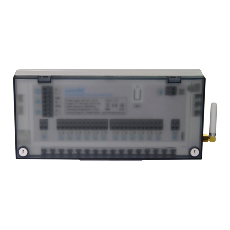
nodon DRB-2-2-00 User manual

Terminal-
Nummer Terminal-
Nummer
DRB-2-2-00 SIN
1➔2
2➔1
3➔3
4➔5
5➔6
6➔4
GEBRAUCHSANWEISUNGDE
HUTSCHIENEN-GEHÄUSE
FÜR FUNKMODULE
Artikelnummer: DRB-2-2-00 • Maximale Stromstärke : lesen Sie das Handbuch des
entsprechenden Moduls • Hutschienen-Gehäuse kompatibel: Typ Ω EN 50022
Kompatible Module: SIN-X-1-XX, SIN-X-2-XX, SIN-X-RS-XX, SIN-X-FP-XX
Betriebstemperatur: -20°C bis 40°C
Abmessungen: 87x27x58 mm • Gewicht: 46 g • Garantie: 2 Jahre
STROMSCHLAGGEFAHR
Empfehlung
VOR DER INSTALLATION MÜSSEN SIE SICHERSTELLEN, DASS DIE
STROMVERSORGUNG UNTERBROCHEN IST. ANSONSTEN BESTEHT
DIE GEFAHR EINES STROMSCHLAGS.
Schalten Sie die Stromversorgung direkt am Sicherungskasten ab, um die Gefahr eines Stromschlags zu
vermeiden. Dieses Hutschienen-Gehäuse ist für eine Verwendung unter Spannung ausgelegt. Eine falsche
Installation kann einen Brand oder einen Stromschlag verursachen. Das Hutschienen-Gehäuse muss unbedingt
unter strengster Einhaltung der Anweisungen dieser Gebrauchsanleitung installiert UND angeschlossenwerden
werden. NodOn® übernimmt keine Haftung für Unfälle oder Schäden, die auf die Nichteinhaltung der
Montageanweisungen zurückzuführen sind. Schalten Sie die Stromversorgung vor jedem Eingriff ab und
nehmen Sie keine Änderungen vor, wenn die LED des Moduls im Hutschienen-Gehäuse leuchtet.
INSTALLATION
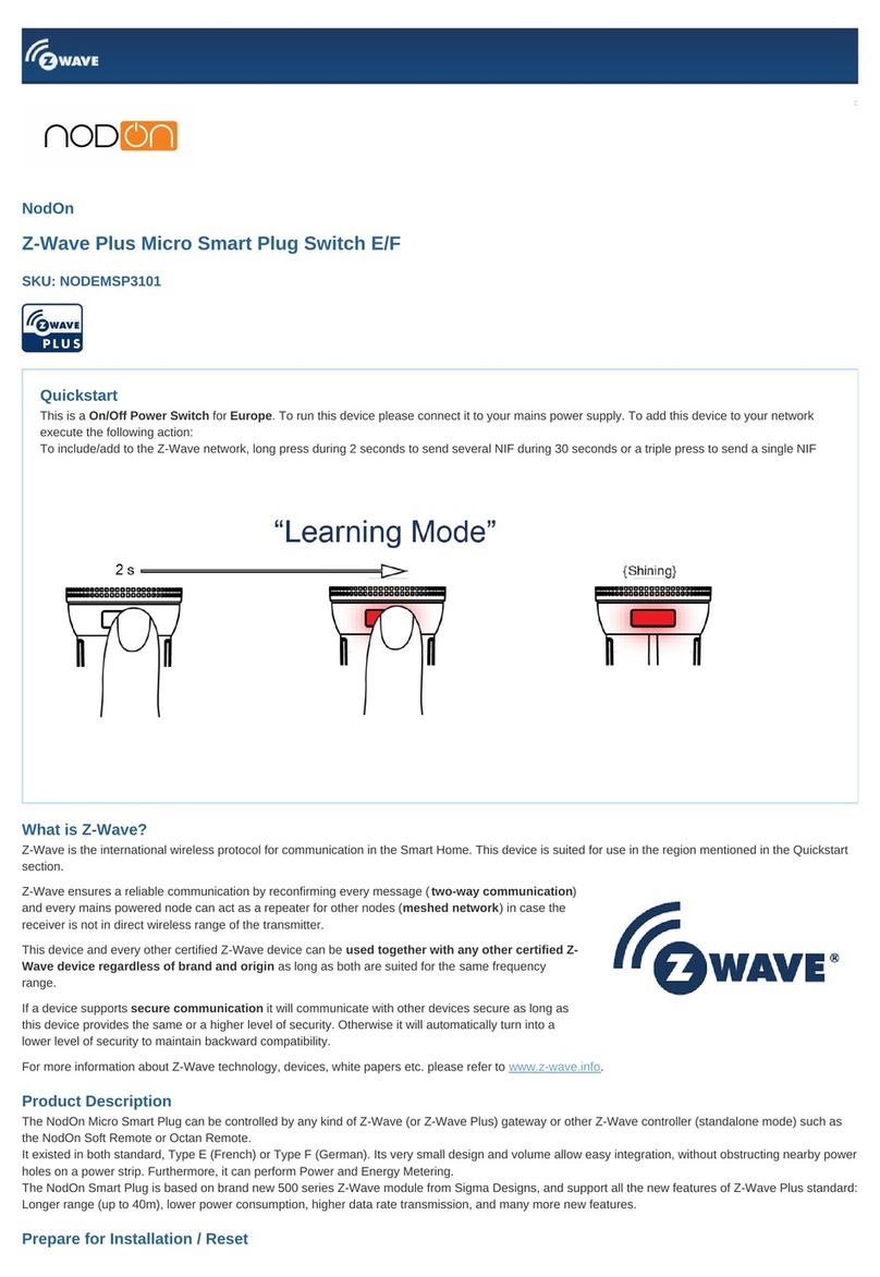
Abbildung 4
Die Leistung jedes Moduls darf 1500W
nicht überschreiten, wenn 3 DIN-
Schienen-Gehäuse gemäß Abbildung
4 in der Schalttafel angeordnet sind.
• Verwenden Sie das Gerät nie, wenn es nicht ordnungsgemäß installiert ist und sich
nicht in einem den geltenden Normen entsprechenden Schaltkasten bendet.
• Halten Sie das Produkt von Flüssigkeiten fern.
nodon.fr/de/ Abschnitt
Bedienungsanleitungen in weiteren Sprachen nden
Sie unter: www.nodon.fr/notices
NodOn SAS
121 rue des Hêtres
45590 St CYR EN VAL (FRANCE)
KONTAKT
SICHERHEITSHINWEISE
KUNDENDIENST
DRB-2-2-00_UGB_DE_V6
GEBRAUCHSANWEISUNG
Gehen Sie direkt zur ausführlichen Anleitung im Support Bereich unter
nodon.fr/de/technische-unterstuetzung/
Installationsanleitung
Stellen Sie die allgemeine Stromversorgung des
Schaltkastens ab.
Öffnen Sie die Klemmen des Moduls, das Sie
anschließen möchten.
Setzen Sie das Modul in das Hutschienen-
Gehäuse ein und achten Sie auf die richtige Richtung
des Moduls, die Klemmleiste muss sich links
benden (siehe Abbildung 1). Überprüfen Sie, ob die
Klemmen genug geöffnet sind, damit die Stifte im
Gehäuse nicht geknickt werden.
Ziehen Sie die 6 Schrauben des Moduls fest, um
die beiden Teile aneinander zu befestigen (siehe
Abbildung 2).
Um das Modul heraus zu nehmen, lösen Sie die 6
Schrauben des Moduls einfach wieder.
Installieren Sie das Gehäuse mit dem Modul auf
die Hutschiene des Schaltkastens.
Schließen Sie die Klemmen entsprechend Ihrem
Modul nach dem Schema an (siehe Abbildung 3).
Abbildung 2
Schalten Sie die allgemeine Stromversorgung wieder ein und prüfen Sie, ob
die LED auf dem Modul am Lichtleiterpunkt leuchtet.
Für das Pairing oder die Konguration Ihres Moduls schlagen Sie bitte in dessen
Gebrauchsanweisung nach.
Abbildung 1
Modul
Taste
Lichtleiter
Terminal
Terminal Abbildung 3
1 2 3 54 6

Terminal
number Terminal
number
DRB-2-2-00 SIN
1➔2
2➔1
3➔3
4➔5
5➔6
6➔4
EN USER GUIDE
DIN RAIL BOX
FOR RELAY SWITCH
Reference: DRB-2-2-00 • Maximum intensity: please refer to the user guide of the
connected relay switch • Compatible DIN Rail: Type Ω EN 50022
Compatible relay switches: SIN-X-1-XX, SIN-X-2-XX, SIN-X-RS-XX, SIN-X-FP-XX
Operational temperature: -20°C to 40°C
Dimension: 87x27x58 mm • Weight: 46g • Warranty: 2 years
DANGER OF ELECTROCUTION
Installation procedure
BEFORE ANY INSTALLATION MAKE SURE THE POWER SUPPLY IS DISCONNECTED
TO AVOID ANY RISK OF ELECTROCUTION.
Directly cut the power supply from the breaker box to avoid any risk of electrocution. This DIN Rail
Box is designed to be used power up, a wrong installation can create a re or an electric shock. The
DIN Rail Box must be installed and connected carefully following the instructions of this user guide.
NodOn®will not be responsible for any loss or damage resulting from a non-respect of the instructions
of this user guide. Cut the power supply before any operation and don’t do any modication if the relay
switch LED located into the Rail DIN Box is ON.
Cut the power supply of the electrical panel.
Unscrew the relay switch terminals you want
to connect.
Insert the relay switch on the DIN Rail Box
while respecting the direction of insertion of the
relay switch, the terminal block must be located
on the left (see gure 1).
Make sure the terminals are well unscrewed and
take care to not fold the pins located inside the
DIN Rail Box.
Screw the 6 screws of the relay switch to x
both elements together (see gure 2).
To facilitate the connection, unscrew
the 6 screws of the DIN Rail Box terminals.
Install the box with the relay switch on
the DIN Rail Box of the electrical panel.
Connect the terminals according to your
module according to the diagram (see gure 3).
gure 3
gure 2
Turn the power supply back on and check that the LED on the module lights up
through the light guide.
For the pairing or conguration of your module, please refer directly to its user
guide.
gure 1
• Never use the device if it is not correctly installed and placed inside an electrical
panel in conformity with the current standards.
• Keep the product far away from liquids.
For user guides in other languages, please visit
www.nodon.fr/notices
NodOn SAS
121 rue des Hêtres
45590 St CYR EN VAL (FRANCE)
CONTACT
USE CAUTIONS
AFTER-SALES SERVICE
Relay
switch
Button
Light guide
1 2 3 54 6
Terminals
Terminals
Recommandation
INSTALLATION
gure 4
The power of each module must not
exceed 1500W if 3 DIN rail boxes are
placed in the switchboard as shown
in gure 4.
DETAILED USER GUIDE
Directly access the detailed user guide on the Support section on
nodon.fr/en/technical-support/
Table of contents
Languages:
Other nodon Home Automation manuals

