Nokia 6090 Installation instructions

Nokia 6090 hardware information

Copyright © 2001. Nokia Mobile Phones. All rights reserved.
ChangeHistory:
ChangeHistory:
Change History:
ChangeHistory:
2.0 14-Feb-01 Specifications Initial version
2.01 06-Jun-01 Specifications Title change from "technical" to "hardware"
Accuracy improvement in ch. 6.2., pin 2 & 3
Copyright © Nokia Mobile Phones 2001. All rights reserved.
Reproduction, transfer, distribution or storage of part or all of the contents in document in
any form without the prior written permission of Nokia is prohibited.
Nokia, Nokia 6090 and Nokia Connecting People are registered trademarks of Nokia
Corporation. Other products and company names mentioned herein may be trademarks
or trade names of their respective owners.
Nokia operates a policy of continuous development. Nokia reserves the right to make
changes and improvements to any of the products described in this document without
prior notice.
Under no circumstances shall Nokia be responsible for any loss of data or income or any
special, incidental, consequential or indirect damages howsoever caused.
The contents of this document are provided "as is". Except as required by applicable law,
no warranties of any kind, either express or implied, including, but not limited to, the
implied warranties of merchantability and fitness for a particular purpose, are made in
relation to the accuracy, reliability or contents of this document. Nokia reserves the right
to revise this document or withdraw it at any time without prior notice.

C
Copyright © 2001. Nokia Mobile Phones. All rights reserved.
Nokia 6090 technical information 3
TABLE OF CONTENTS
1 INTRODUCTION..................................................................................................................... 4
2 SYSTEM OVERVIEW............................................................................................................. 4
3 TRANSCEIVER FEATURES LIST AND DIMENSIONS ......................................................... 6
4 BASIC SPECIFICATIONS...................................................................................................... 7
5 TRANSCEIVER DRAWINGS.................................................................................................. 8
6 DATA CONNECTOR DESCRIPTION AND PINNING ............................................................ 9
6.1 DATA CONNECTOR DESCRIPTION ...........................................................................................9
6.2 DATA CONNECTOR PINNING................................................................................................... 9
7 SYSTEM CONNECTOR DESCRIPTION AND PINNING...................................................... 10
7.1 SYSTEM CONNECTOR DESCRIPTION ..................................................................................... 10
7.2 SYSTEM CONNECTOR PINNING............................................................................................. 12
8 ADDITIONAL INFORMATION.............................................................................................. 12
Table 1: Overall transceiver dimensions...........................................................................6
Table 2: Basic specifications............................................................................................7
Table 3: Pinning of the data connector (RS-232 Interface)...............................................9
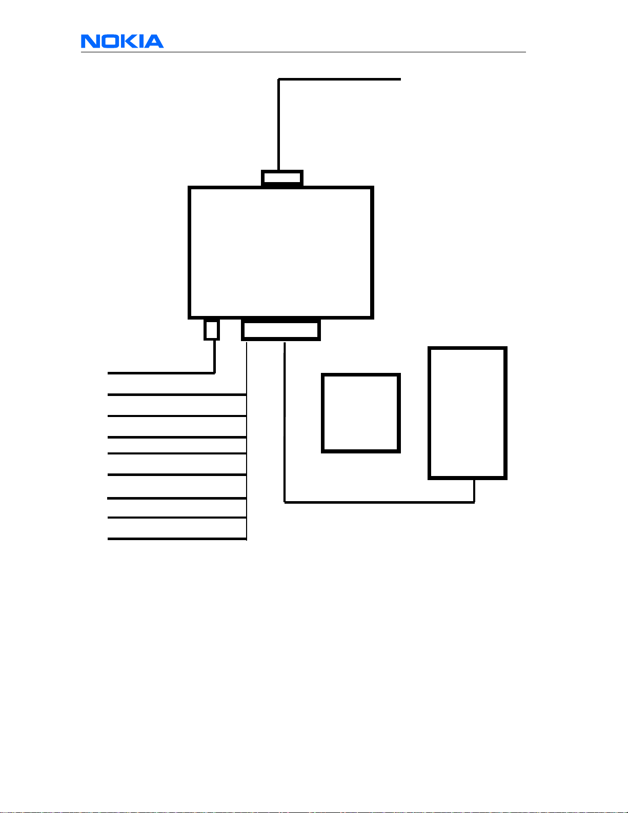
Figure 1 : System overview of Nokia 6090.......................................................................5
Figure 2: Dimensions of transceiver (front view)...............................................................6
Figure 3: Dimensions of transceiver (top view).................................................................6
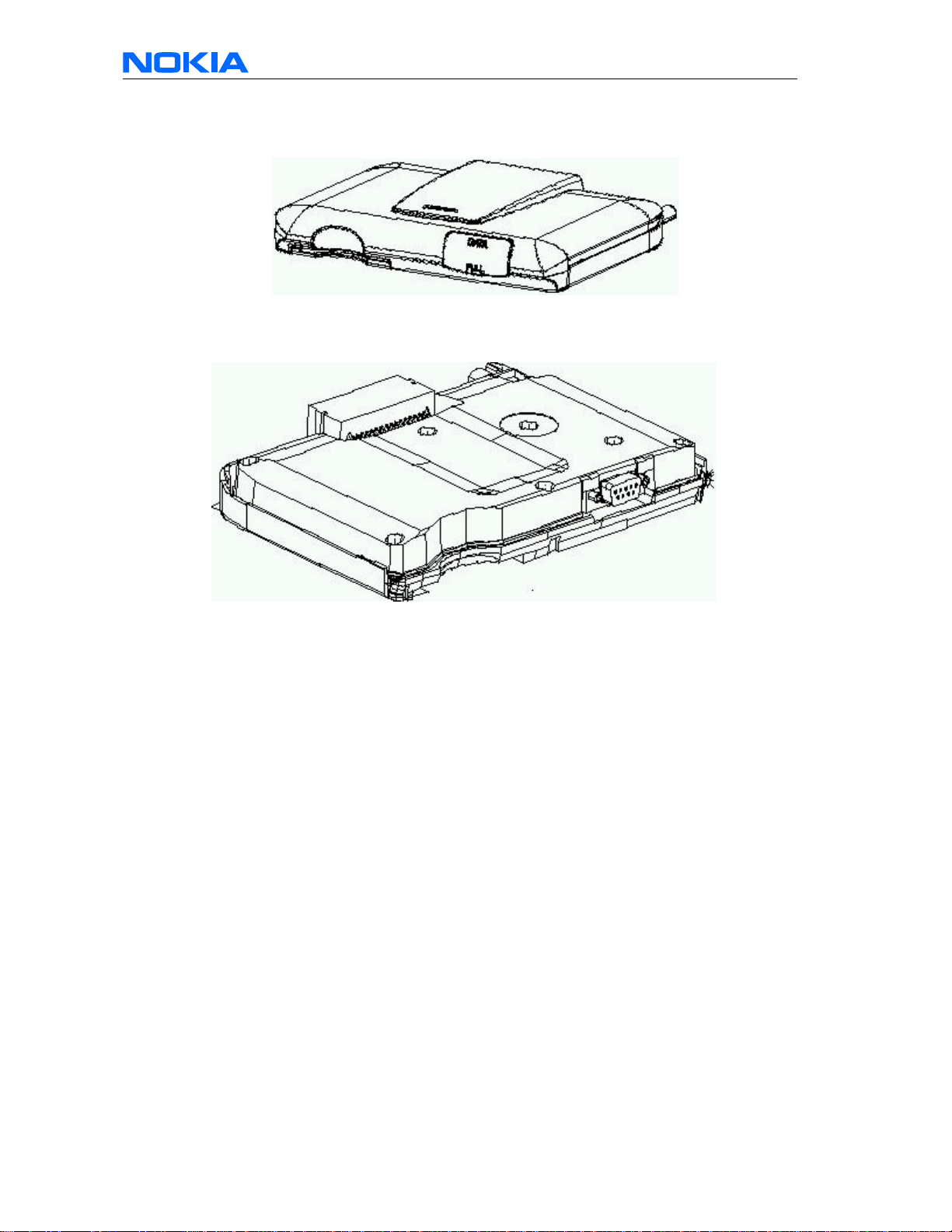
Figure 4: Nokia 6090 transceiver (with housing)...............................................................8
Figure 5: Nokia 6090 housing open..................................................................................8
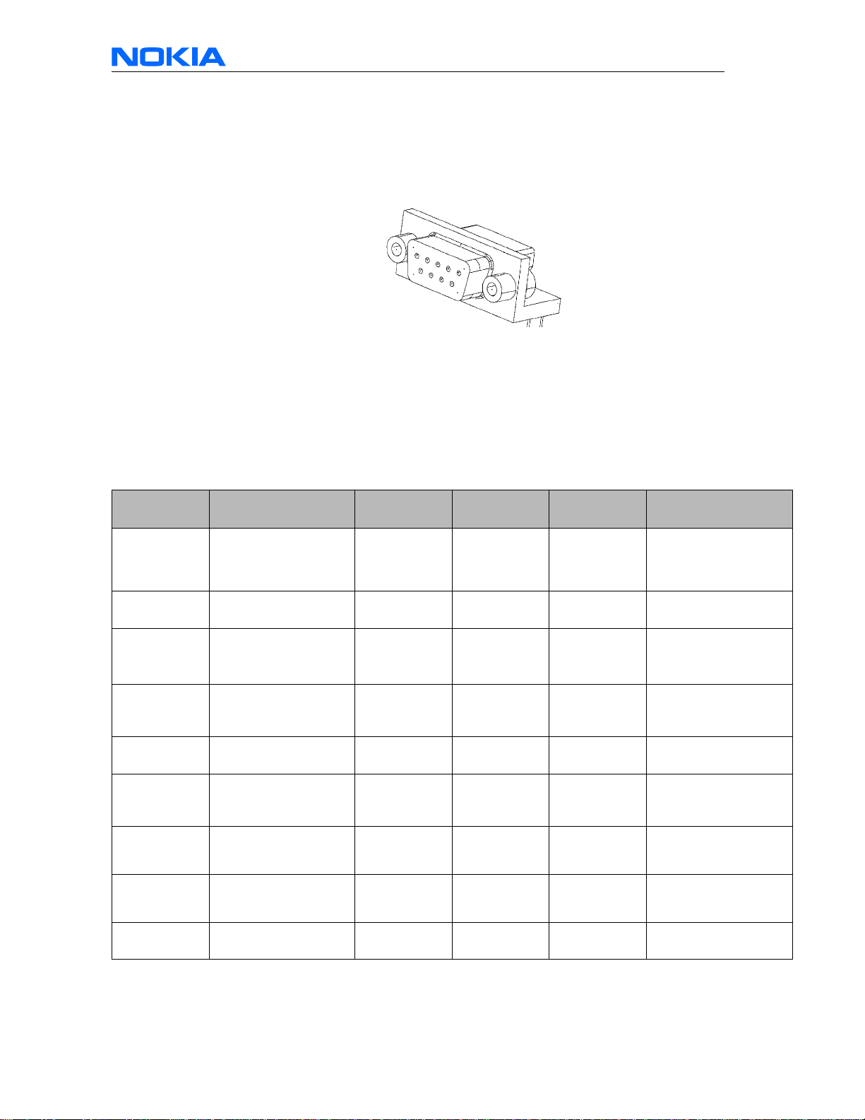
Figure 6: Nokia 6090 integrated data connector (front view)............................................9
Figure 7: System connector (transceiver side) ...............................................................10
Figure 8: System connector (system cable side)............................................................11
Figure 9: Pinning of the system connector .....................................................................12

C
Copyright © 2001. Nokia Mobile Phones. All rights reserved.
Nokia 6090 technical information 4
1 Introduction
This document describes the Nokia 6090 integrated-modem vehicle fixed-mounted GSM
phone. It is aimed for companies who need technical information before choosing a
device to be integrated in their vehicles/solution. This document focuses on information
related to the Nokia 6090 product. Information related to features supported by its
software, e.g. AT commands, can be found in a separate document.
Other technical information is confidential but may be passed upon application per e-mail
to:
6090.Product[email protected]
Technical questions related to the Nokia 6090 can be sent to above-mentioned address.
The Nokia 6090 provides internal data functionality. It means that no external device like
data card is necessary to connect a terminal like a PC to the phone.
The means to connect the Nokia 6090 to the external device can be as simple as a
standard modem cable that is available in computer stores.
2 System Overview
The NOKIA 6090 is a fixed carphone that consists in 3 main units. The GSM transceiver
is the main part of the phone; it consists of an 8W GSM-transceiver, the power supply,
the handsfree circuit, a SIM-Card reader for a big SIM card, a data interface via D-Sub 9
connector (fully implemented EIA/TIA 8 signals RS232), and has an interface to car
specific signals. The handset consists of a large display, a 16 key keyboard with NAVIä
key, an ear speaker, a microphone and an SIM-Reader for a small SIM card. The cradle
holds the handset and contains a magnet for Hook On/Off detection in the handset. For
modem applications it is also possible to operate the GSM-transceiver without neither the
cradle nor the handset. The product without handset is called Nokia 6090 application kit
(You can mention the Nokia product code 063497 to your dealer).
The following picture shows a system overview of the Nokia 6090.

C
Copyright © 2001. Nokia Mobile Phones. All rights reserved.
Nokia 6090 technical information 5
System connector
DSUB-9
RF
Transceiver
RS 232 to PC or to
compatible external
device
Antenna
Hand
set
Cradle
Car battery
Ignition (IGN)
Car-radio mute (CRM)
Antenna Motor Control (AMC)
Backlight dimming (BLD)
Microphone
Loudspeaker
Line out
For installation, please refer to installation
guide (included in user manual)
Figure 1: System overview of Nokia 6090
The transceiver is the main part of the Product; it contains the GSM radio part. Its has 3
connectors:
1 System connector (powersupply, car signals, audio signals, handset interface)
2 RF connector (to GSM antenna, note a mini UHF adapter may be needed)
3 Data Connector (to a compatible PC or any other compatible device)

C
Copyright © 2001. Nokia Mobile Phones. All rights reserved.
Nokia 6090 technical information 6
3 Transceiver features list and dimensions
•Class 2 (8W) phase GSM 900 transceiver
•Powersupply 12 V typical
•Support of ignition sense and back-light dimming signals
•Delivery of car-radio mute and antenna motor control signals
•High quality handsfree audio (designed for vehicle environment)
•Power amplifier for 4W handsfree loudspeaker
•Support of active handsfree microphone according to VDA standard
•Delivery of lineout signal to use the car-radios amplifiers and loudspeakers for
handsfree
•SIM reader for large SIM-Card
•RS-232 interface for connections to compatible external device
•Connection to handset
•Car data interface for remote control and data applications
Height 25mm
Width 170mm
Depth 115mm
Volume 489ccm
Table 1: Overall transceiver dimensions
Figure 2: Dimensions of transceiver (front view)
Figure 3: Dimensions of transceiver (top view)

C
Copyright © 2001. Nokia Mobile Phones. All rights reserved.
Nokia 6090 technical information 7
4 Basic Specifications
Parameter Type
Cellular System GSM 900 Phase II
Transceiver type Class 2 Mobile (8 Watt)
System cable Interface 32 pole AMP connector
Data Interface RS232 (full protocol)(DSUB 9)
Installation Trunk, cabin or DIN slot
SIM card Full size SIM in RU (ISO 7816)
Mini SIM in HS (ISO 7816)
Operational temperature -20 C to + 60 C (normal performance)
-40 C to + 85 C (reduced performance)
-40 C to + 85 C (storage)
Supply voltage (transmitting) 10.8 V to 16 V
Current consumption (power off) < 1mA
Current consumption (idle mode) 150mA
Current consumption (transmit at max.
PWR) normal:1,5A maximal: 4A (peak)
Fuse +12V Fuse 3A
GND Fuse 3A
IGNS Fuse 1A
PCB Fuse for Fire protection
TX RF output power 8 Watt
Handsfree audio power 5 Watt at 4Ohm
Table 2: Basic specifications

C
Copyright © 2001. Nokia Mobile Phones. All rights reserved.
Nokia 6090 technical information 8
5 Transceiver drawings
Figure 4: Nokia 6090 transceiver (with housing)
Figure 5: Nokia 6090 housing open

C
Copyright © 2001. Nokia Mobile Phones. All rights reserved.
Nokia 6090 technical information 9
6 Data connector description and pinning
6.1 Data connector description
Figure 6: Nokia 6090 integrated data connector (front view)
Name of the connector counterpart (wire side): D-SUB 9
Possible names of the connector counterpart cable: standard modem cable, extension
cable for modem/mouse/monitor, DB9-DB9 cable, female-male 9 pin serial cable.
6.2 Data connector pinning
The following table describes pin-out of the data connector:
Pin /
Connector Line Symbol Minimum Typical /
Nominal Maximum Unit / Notes
1RS-232 DCD
Handshake: Data
Carrier Detect
(output)
+/- 3,3 +/-5,4 +/- 15 V/ inactive
V /active
2RS-232 RD
Received Data (output) +/- 3,3 +/-5,4 +/-15 V / binary state 1
V / binary state 0
3RS-232 TD
Transmitted data
(input)
- 1,2 / 1,5 - V/ binary state 1
V/ binary state 0
4RS-232
DTR
(input)
- 1,2 / 1,5 - V / inactive
V / active
5GND
(Power Supply) 0 V/ reference ground
6RS-232
DSR
(output)
+/- 3,3 +/-5,4 +/- 15 V / inactive
V/ active
7RS-232
RTS
(input)
- 1,2 / 1,5 - V / inactive
V/ active
8RS-232
CTS
(output)
+/- 3,3 +/-5,4 +/- 15 V / inactive
V/ active
9RI
(output) +/- 3,3 +/-5,4 +/- 15 V / inactive
V/ active
Table 3: Pinning of the data connector (RS-232 Interface)

C
Copyright © 2001. Nokia Mobile Phones. All rights reserved.
Nokia 6090 technical information 10
7 System connector description and pinning
7.1 System connector description
Figure 7: System connector (transceiver side)

C
Copyright © 2001. Nokia Mobile Phones. All rights reserved.
Nokia 6090 technical information 11
Name of the connector counterpart (wire side):
The Shield for MQS (Connector at Cable side) AMP 929053-1 looks as follows:
Figure 8: System connector (system cable side)

C
Copyright © 2001. Nokia Mobile Phones. All rights reserved.
Nokia 6090 technical information 12
7.2 System connector pinning
The following table consists of the pin out of the system connector. The connections on
the system connector are shown in the following table, I/O's are given in view from the
radio unit (transceiver).
Pin No. Name Function Direction Type
1 CARBAT+ Battery Plus Input Power (10.8V.16V)
2 CARBAT- Battery Minus Input Power (0V)
3 BLD Back light dimming Input PWM 12V
4 AMC Antenna-Motor Control Output Open collector (active
high)
5,6 N.C.
7 to Handset
8 to Handset
9 to Handset
10 to Handset
11 SHIELD Line out Shield for Lineout Output Power/Analog
12 N.C.
13 LineOutP Line Output (pos.) Output Analog
14 LineOutN Line Output (neg.) Output Analog
15, 16 N.C.
17 CARBAT+ Battery Plus Input Power (10.8V.16V)
18 CARBAT- Battery Minus Input Power (0V)
19 IGS Ignition Sense Input Dig. 12V
20 CRM Car-Radio Mute Output Open Collector (active
low)
21, 22 N.C.
23 to Handset
24 to Handset
25 to Handset
26 to Handset
27 HFMICGND handsfree Microphone GND Output Power/Analog
28 HFMICP handsfree Microphone +8V/In I/O Analog
29, 30 N.C.
31 HFSPKN handsfree loudspeaker (neg.) Output Analog
32 HFSPKP handsfree loudspeaker (pos.) Output Analog
Figure 9: Pinning of the system connector
8 Additional information
Additional information is confidential but may be available upon application per e-mail to:
6090.productsupport@nokia.com
Please mention company, web site address, your full name, full postal address, the kind
of application the development is for and other details you may find useful for us to know
about.
Technical questions related to the Nokia 6090 can be sent to above-mentioned address.
Other manuals for 6090
6
Table of contents
Other Nokia Cell Phone manuals

Nokia
Nokia 6085 User manual

Nokia
Nokia 2760 - Cell Phone 11 MB User manual

Nokia
Nokia 1661 User manual

Nokia
Nokia 8810 Quick start guide

Nokia
Nokia Cellphone 3600 User manual

Nokia
Nokia N 80 User manual

Nokia
Nokia X1-00 User manual

Nokia
Nokia E6-00 Quick start guide

Nokia
Nokia 8310 Quick start guide

Nokia
Nokia 6316s-1 User manual

Nokia
Nokia X3 User manual

Nokia
Nokia 7390 - Cell Phone - WCDMA Quick start guide

Nokia
Nokia XpressMusic 5310b User manual

Nokia
Nokia 6630 - Smartphone 10 MB User manual

Nokia
Nokia 1255 User manual

Nokia
Nokia 6500 Slide User manual

Nokia
Nokia 6275i User manual

Nokia
Nokia 6126/H User manual

Nokia
Nokia N 80 User manual

Nokia
Nokia 8310 Service manual