Nokia RH-23 Series Service manual

Customer Care Solutions
RH-23 Series Transceivers
Issue 1 03/2004 Nokia Corporation
Service Tools

RH-23 Company confidential
Service Tools CCS Technical Documentation
Page 2 Nokia Corporation. Issue 1 03/2004
[This page intentionally left blank.]

CCS Technical Documentation
Company confidential RH-23
Issue 1 03/2004 Copyright Nokia. All rights reserved.. Page 1
DA-11 Docking Station Adapter and RF Coupler SA-36.............................................. 3
MJ-17 Module Test Jig .................................................................................................. 6
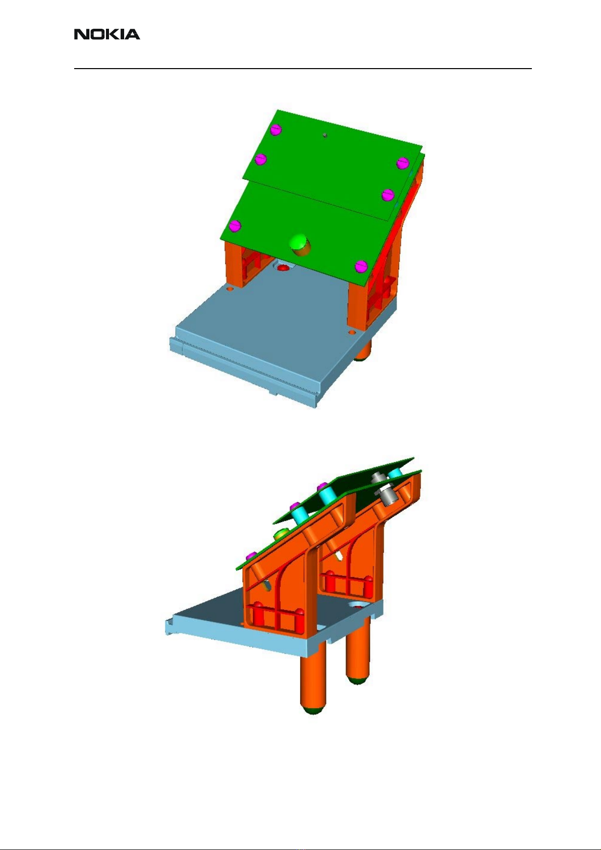
RJ-14 Soldering Jig........................................................................................................ 8
SK-9 PA Component Rework Kit.................................................................................. 9
SK-5 Rework Kit for FM radio.................................................................................... 10
SS-28 Dome Sheet Assembly Jig................................................................................. 11
FPS-8 Flash Prommer (Sales Pack) ............................................................................. 13
FPS-8C Parallel Flash Prommer (Sales Pack) ............................................................. 14
ACF-8 Universal Power Supply .................................................................................. 15
SF-11 POS (Point Of Sale) Flash Loading Adapter .................................................... 16
FLC-2 DC Cable .......................................................................................................... 18
AXS-4 Service Cable ................................................................................................... 19
XCS-1 Service Cable ................................................................................................... 20
SW Security Device PKD-1......................................................................................... 21
FLS-4S POS (Point Of Sale) Flash Device (Sales Pack)............................................. 22
PCS-1 Power Cable...................................................................................................... 23
XRF-1 RF Cable .......................................................................................................... 24
DAU-9S FBUS Cable .................................................................................................. 25
SCB-3 DC Cable.......................................................................................................... 26
XCS-4 Modular Cable ................................................................................................. 27
Printer Cable ................................................................................................................ 28
CA-6UT Service Audio Cable ..................................................................................... 29

RH-23 Company confidential
CCS Technical Documentation
Page 2 Copyright Nokia. All rights reserved. Issue 1 03/2004

CCS Technical Documentation
Company confidential RH-23
Issue 1 03/2004 CopyrightNokia. All rights reserved Page 3
DA-11 Docking Station Adapter and RF Coupler SA-36
The SA-36 is used with DA-11 for RF testing. RF tuning is not allowed by SA-36. It has
been designed for calibration and soft ware update use. The Docking Station Adapter
makes signal connections to the phone.
DA-11 main electric functions include:
• adjustable VBATT calibration voltage, current measurement limit voltage "VCHAR", current mea-
surement calibration current "ICHAR"
• adjustable ADC calibration voltage via BTEMP and BSI signal
• BTEMP and BSI calibration resistor
• signals from FBUS to the phone via parallel jig
• control via FBUS or USB
• Flash OK/FAIL indication
In calibration mode DA-11 is powered by external power supply 11-16V DC. In flashing
power for the phone can be taken from FPS-8 or external power supply 11-16V DC.
DA-11 main electric functions are:
• phone recognizing from BTEMP
• filters of FBUS signals

RH-23 Company confidential
CCS Technical Documentation
Page 4 CopyrightNokia. All rights reserved Issue 1 03/2004
Product Code
DA-11 Docking Station Adapter: 0770587
SA-36 RF Coupler: 0770726
Figure 1: View of DA-11 Docking Adapter

CCS Technical Documentation
Company confidential RH-23
Issue 1 03/2004 CopyrightNokia. All rights reserved Page 5
Figure 2: RF Coupler SA-36

RH-23 Company confidential
CCS Technical Documentation
Page 6 CopyrightNokia. All rights reserved Issue 1 03/2004
MJ-17 Module Test Jig
Module Test Jig MJ-17 is designed for 1AQ and 1BF (upper block) testing. It can be used
for flashing, system testing and troubleshooting.
MJ-17 take in use instructions
UI board assy has been semi fixed in jig.
Upper block flex assy with needed spare parts and without the earpiece has to be assem-
bled to the jig and can be changed when needed.
Engine pwb is just pressed in place. Please ensure the flex pwb connector and the RF
connector are properly connected. If problems occur with RF connection between an RF
connector and an RF probe, you can help it by loosening an RF probe from the bottom of
the jig and help connecting by hand.
Instructions to assemble the upper block parts to the module jig
The phone spare parts needed in the module jig to have the upper block functionality in
the jig:
1 Upper block flex assy (0263440). NOTE: Earpiece has to be removed before
assembling upper block flex assy to the jig!!
2 LCD module 128X128 (4850347)
3 LCD module B/W 96X36 (4850361)
4 VGA camera module (4858023)
5 Shield small VGA camera (9511279)
Instructions to assemble the parts to the jig:
1Remove earpiece from Upper block flex assy
2 Assemble parts 2-4 (on the list above) to upper block flex assy
3 Loosen upper block locking screws of the module jig
4 Insert upper block flex assy to the jig and ensure connector on flex pwb is con-
nected
5 Tighten screws to keep upper block flex assy in place

CCS Technical Documentation
Company confidential RH-23
Issue 1 03/2004 CopyrightNokia. All rights reserved Page 7
Product Code
MJ-17 Module Test Jig: 0770586
Figure 3: View of MJ-17
Note: The nominal supply voltage for MJ-17 is 4.0 V.
Over voltage protection operates at 4.5V.
If overvoltage protection is triggered, the normal jig operation can be restored by
switching OFF the power supply, replacing the fuse (if not OK) and restoring valid
power supply.
MJ-17 includes over voltage, overcurrent and reverse polarity protection.

RH-23 Company confidential
CCS Technical Documentation
Page 8 CopyrightNokia. All rights reserved Issue 1 03/2004
RJ-14 Soldering Jig
RJ-14 Soldering Jig is used for soldering and as a rework jig for WV8 module.
Product Code
RJ-14 Module Jig: 0770589
Figure 4: View of RJ-14

CCS Technical Documentation
Company confidential RH-23
Issue 1 03/2004 CopyrightNokia. All rights reserved Page 9
SK-9 PA Component Rework Kit
SK-9 PA Rework Kit includes ST-11 Rework Stencil and RJ-21 PA Rework Jig. SK-9 is used
for paste spreading for the microLGA PA component.
ST-11 and RJ-21 can be ordered separately or as the whole SK-9 PA Rework Kit.
Product Codes
SK-9 PA Component Rework Kit: 0274819
ST-11 PA Rework Stencil: 0770881
RJ-21 PA Rework Jig: 0770849
Figure 5: View of SK-9 incl. ST-11 (above) and RJ-21 (below)

RH-23 Company confidential
CCS Technical Documentation
Page 10 CopyrightNokia. All rights reserved Issue 1 03/2004
SK-5 Rework Kit for FM radio
Includes ST-5 Rework Kit and RJ-24 Rework jig.
Product codes:
SK-5 Rework Kit: 0274507
ST-5 Rework Stencil for FM radio: 0770691
RJ-24 Rework Jig for FM radio: 0770688

CCS Technical Documentation
Company confidential RH-23
Issue 1 03/2004 CopyrightNokia. All rights reserved Page 11
SS-28 Dome Sheet Assembly Jig
SS-28 Dome Sheet Assembly Jig is used for the dome sheet assembling.
Product Code
SS-28 Dome Sheet Assembly Jig: 0770872
Figure 6: SS-28 Dome Sheet Assembly Jig

RH-23 Company confidential
CCS Technical Documentation
Page 12 CopyrightNokia. All rights reserved Issue 1 03/2004
[This page left intentionally blank.]

CCS Technical Documentation
Company confidential RH-23
Issue 1 03/2004 Nokia Corporation. Page 13
FPS-8 Flash Prommer (Sales Pack)
The Flash Prommer FPS-8 is used with e.g. DA-11 and JBV-1. Power is supplied to FPS-8
from the Universal Power Supply.
The sales pack includes:
- FPS-8 Flash Prommer 0750123
- FPS-8 Activation Sheet 9359289
- Universal Power Supply 0680032
- AXS-4 Service Cable (D9-D9)0730090
- Printer cable 0730029
Sales package code
FPS-8 Flash Prommer: 0080321
Figure 1: View of FPS-8

RH-23 Company confidential
CCS Technical Documentation
Page 14 Nokia Corporation. Issue 1 03/2004
FPS-8C Parallel Flash Prommer (Sales Pack)
The Parallel Flash Prommer FPS-8C is used with DA-11 and JBV-1. Flash programming
can be done to maximum of 8 phones parallel. FPS-8C consists of eight SF11C program-
ming cards. SF11C card is functionally identical to FPS-8.
Sales package code
FPS-8C Parallel Flash Prommer: 0080396
Figure 2: View of FPS-8C

CCS Technical Documentation
Company confidential RH-23
Issue 1 03/2004 Nokia Corporation. Page 15
ACF-8 Universal Power Supply
ACF-8 Universal Power Supply is used to power FPS-8. ACF-8 has 6 V DC and 2.1 A out-
put.
Product Code
ACF-8 Universal Power Supply: 0680032
Figure 3: View of ACF-8
-8

RH-23 Company confidential
CCS Technical Documentation
Page 16 Nokia Corporation. Issue 1 03/2004
SF-11 POS (Point Of Sale) Flash Loading Adapter
SF-11 POS Flash Loading Adapter is used in place of the phone's normal battery during
service, to supply a controlled operating voltage.
Product Code
SF-11 POS Flash Loading Adapter: 0770588
Figure 4: View of SF-11

CCS Technical Documentation
Company confidential RH-23
Issue 1 03/2004 Nokia Corporation. Page 17
FLC-2 DC Cable
The FLC-2 is used to supply a controlled operating voltage.
Product Code
FLC-2 DC Cable: 0730185
Figure 5: View of FLC-2
2

RH-23 Company confidential
CCS Technical Documentation
Page 18 Nokia Corporation. Issue 1 03/2004
AXS-4 Service Cable
The AXS-4 D9-D9 Service Cable is used to connect two 9 pin D connectors e.g. between
PC and FPS-8. Cable length is 2 meters.
Product code
AXS-4 D9-D9 Service Cable: 0730090
Figure 6: View of AXS-4
Other manuals for RH-23 Series
1
Table of contents
Other Nokia Cell Phone manuals

Nokia
Nokia 2366i - Cell Phone - Verizon Wireless User manual

Nokia
Nokia 6650 FOLD User manual

Nokia
Nokia RM-4 Guide

Nokia
Nokia 306 User manual

Nokia
Nokia TA-1474 User manual

Nokia
Nokia 6133 - Cell Phone 11 MB User manual

Nokia
Nokia 5140 User manual

Nokia
Nokia 5235 User manual

Nokia
Nokia NSERIES N95-1 User guide

Nokia
Nokia Lumia 1320 User manual