Nomadic NC-X3 Manual

NC-X3 Install Manual
16680 N 51st Ave Units 4 & 5
Glendale, AZ 85306
(480) 576-2489
www.NomadicCooling.com/Support
Version 2.0-082923

NC-X3 Install Manual Version 2.0-082923 2 Nomadic Cooling Co
TABLE OF CONTENTS
ITEMIZED PARTS LIST .....................3
IMPORTANT SAFETY INSTRUCTIONS......5
NC-X3 SPECIFICATIONS...................6
INSTALLATION INSTRUCTIONS............7
ELECTRICAL WIRING DIAGRAM ..........12
INTRODUCTION
The NC-X3 Air Conditioner (“AC unit”) is de-
signed and intended for instalation on the
roof of a recreational vehicle during or after
the vehicle is manufactured.
The NC-X3 can be installed by one person
with brief help from one additional person.
Reading this instalation manual in its entire-
ty first will ensure the proper instalation and
function of the NC-X3.
Nomadic Cooling reserves the right to modify
appearance and specifications without notice.
Always bench test AC unit
before installing.
Check to ensure all required parts are
included (see page 3).
Keep a record of the following information:
Model No.
Serial No.
Date Purchased
Installed By
@ nomadiccooling
Get social with us!
16680 N 51st Ave Units 4 & 5
Glendale, AZ 85306
(480) 576-2489
www.NomadicCooling.com/Support
NC-X3Rooftop AC |Volt
12
24
48
Nomadic Cooling Co 3 NC-X3 Install Manual Version 2.0-082923
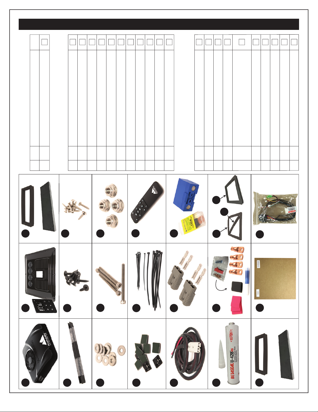
ITEMIZED PARTS LIST
GH
JKL
MN O
PQ
P
S
I
ABC
DEF
D
K
M
O
U V
R
T
Option A
Option B
Option A
Option B
BOX 1: NC-X3 Air Conditioning Unit
ID Qty Part Name √
A 1 NC-X3 Air Conditioner
BOX 2: Vent Plate
B 1 Vent pate w/ 4 vents and LCD control panel
C 1 Foam filter air separator (Option A or B)
D 2 Crossbars
E 9 Back (preferred) vent pate self-drilling screws
F 9 Silver (alternative) vent pate screws
G 10 Washers
H 4 Mounting bolts
I 4 Mounting nuts
J 10 Sticky pates for zip ties
K 20 Zip ties (10 arge + 10 small)
L 1 Remote Control
BOX 3: Wiring Kit
M 1 Wiring harness (15 ft)
N 1 Bagged Anderson clip and metal connectors
O 1 Bagged Victron fuse holder and 125A fuse
P 1 Tube of BetaSeal U428+HV and pastic tip
Q 1 Sealed Bag with 2 AWG 5/16” lugs, 3 red and
1 back heat shrink 3/4“, and 1 thread locker
R 1 Foam gasket (A) or Premium Gasket (B)
S 1 Leveling strip
T 1 Foam filter air separator (Option A or B)
U 1 Cardboard tempate
V 1 Sealed bag with control panel wiring bundle
Option A ROption B
NC-X3 Install Manual Version 2.0-082923 4 Nomadic Cooling Co
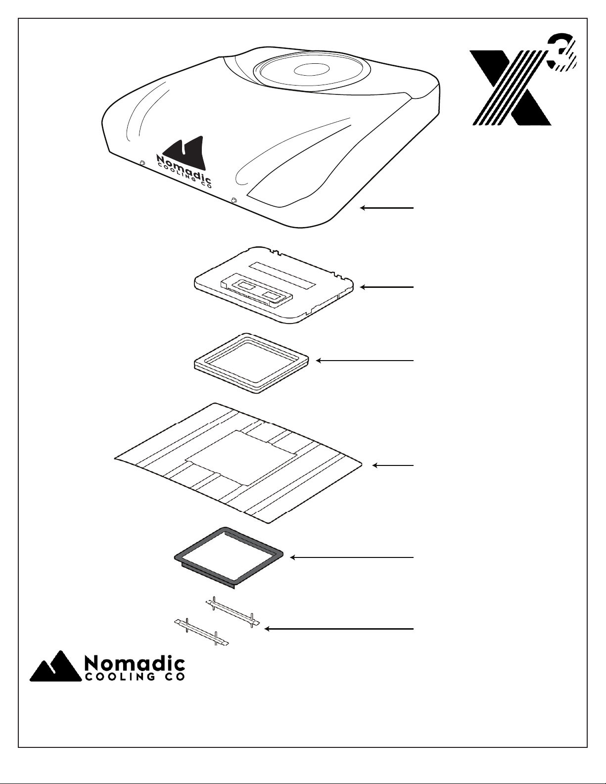
AC Base Plate
AC Unit and Shroud
Foam Gasket
Vehicle Roof
Trim Ring
Cross Bars
16680 N 51st Ave Units 4 & 5
Glendale, AZ 85306
(480) 576-2489
www.NomadicCooling.com/Support
Nomadic Cooling Co 5 NC-X3 Install Manual Version 2.0-082923
This guidebook contains safety guidelines
and instructions that can aid in reducing or
eliminating the risk of accidents and injuries.
A. Recognizing Safety Information
The safety alert symbol is utilized to notify
potential physical injury hazards. To avoid
possible injury or death, follow all safety
messages that come after this symbol.
B. Understanding Signal Words
Signal words identify safety and property
damage messages and indicate the degree
of hazard seriousness.
WARNING is used for hazardous situ-
ations that could result injury (includ-
ing death, severe, moderate or minor
injury if not avoided.
NOTICE is used for situations that
could result in AC unit or vehicle
damage or unnecessary complications
in the instalation process.
HELPFUL TIP is used for useful
information or best practices.
C. Supplemental Directives
To avoid potential injury and even death,
read and follow all of the safety information
and instructions.
Read and comprehend these instructions
before installing, using, servicing, or maintain-
ing this AC unit. Poor instalation, operation,
servicing, or maintenance of this AC unit can
result in severe injury. Follow all instructions.
The instalation must comply with all appli-
cable local and national codes, including the
atest edition of the following standards:
USA
• ANSI/NFPA70, National Electrical
Code (NEC)
• ANSI/NFPA1192, Recreational
Vehicle Code
CANADA
• CSA C22 1. Parts I & II,
Canadian Electrical Code
• CSA Z240 RV Series,
Recreational Vehicles
D. General Safety Messages
WARNING - Failure to follow the subsequent
warnings could lead to death or serious injury.
• A qualified service technician MUST
install or service this product.
• Do NOT modify this product in any
way. Modifications can be extremely
dangerous and void any warranties.
• Do NOT add any devices or accessories
to the AC unit unless specifically
authorized in writing by Nomadic
Cooling Co.
IMPORTANT SAFETY INSTRUCTIONS
NC-X3 Install Manual Version 2.0-082923 6 Nomadic Cooling Co
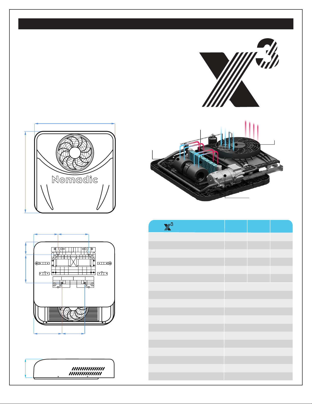
NC-X3 SPECIFICATIONS
Battery Powered
Air Conditioner
12V | 24V | 48V
Ultra Slim
Evaporator
Condenser
Fan (14”)
Brushless
Internal Fan
12/24V/48V
Compressor
12V 24V48V
MODEL
Current ECO Mode 50A 30A 14A
Current MAX Mode 110A 55A 27A
Rated Power 1,320W 1,320W 1,320W
Fuse Size 130A 80A 50A
Power Cord Specification 2AWG 2AWG 4AWG
Rated Cooling Capacity (BTU) 11,830 13,250 15,120
Refrigerant R134a @ 600g ± 30g
Refrigerant Oil POE68
Speed Range 1,000 to 3,000 RPM
Weight 57.3 lbs
Interior Facepate Dimensions 16.25” x 16.25“ (flush)
Compressor Motor 18” PWM, Spring Bushings
Evaporator Motor Brushless with 10“ Fan
Condensor Fan 14”
Noise (Decibals) ≤ 60 dBa
Operation Modes Auto/ECO/Powerful/Fan
Min-Max Temperature Settings 60°F to 86°F
Warranty Two (2) Years
31.33”
31.5”
8.67”10.85”
10.91” 4.93”
9.29” 11.81”
Low
Profile
7.36”
Nomadic Cooling Co 7 NC-X3 Install Manual Version 2.0-082923
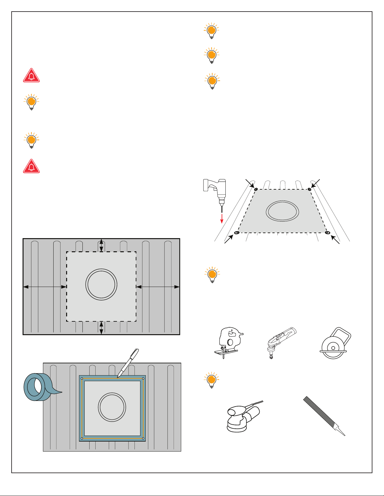
INSTALLATION STEPS
1. Mark your 14”x 14” rooftop opening.
Cut from the exterior of your vehicle.
Never cover AC top fan.
When determining AC unit location,
be sure to allow for the hood/cover
when positioned on the roof.
Make sure there is no electrical or
other encumbrances in the way.
Do not cut into structural beams.
2. Make sure the panned opening is
centered from all four sides. This gives
the best chance for easy instalation.
Use painter’s tape and a permanent
marker to draw your 14”x 14” cutline.
Make multiple passes with the marker.
If you make a mistake repace the
tape and try again. Measure repeat-
edly to make sure your lines create a
perfect 14”x 14” square.
3. Drill each corner of your markings
through the roof. This will make it easier
to detect the location of your 14”x 14”
opening from the underside of your roof.
Use a 1/8” drill bit for corner holes.
4. Cut on your lines using a jig saw, nibbler
or cutting wheel.
Use a sander or file to smooth out the
rough edges after cutting.
14”
14”
14”14”
Exterior Roof
Vehicle Front
Exterior Roof
14”
14”
14”14”
Exterior Roof

NC-X3 Install Manual Version 2.0-082923 8 Nomadic Cooling Co
5. Paint around the edges of the cut roof
opening to prevent rust. You can use any
color rust-preventative paint.
6. Remove tape and clean surface.
7. Remove Nomadic Cooling 14”x 14” water-
proof gasket from packaging.
Make sure area/paint is clean, dry and
clear of all debris.
Use alcohol wipes or PrepSol to
remove oil or wax from vehicle roof.
If your AC unit included a premium
gasket, skip to step 8.
If pacing gasket over a high or uneven
roof surface, remove small amounts of the
14”x 14” gasket to match roof contours.
Use bade to cut away gasket
if needed.
Pace the gasket sticky side down.
8. Apply window weld around 14”x 14”
gasket, after sticking it down.
9. Pace AC unit on roof over 14”x 14” gasket
gently. Measure side-to-side until unit is
centered on all four sides.
Be careful not to puncture, rip
or tear the gasket with AC unit’s
mounting bolts.
Do not put adhesive on top of gasket.
Do not damage electrical components
when pacing unit.
Exterior Roof
Exterior Roof
URETHANE ADHESIVE
CUTAWAYS FOR ROOF RIDGES
Dual Layer Premium Gasket
High compression foam
Low compression foam

Nomadic Cooling Co 9 NC-X3 Install Manual Version 2.0-082923
10. From inside the vehicle add support
brackets to mounting bolts to attach
AC unit to the roof.
Hand tighten all four bolts then 1/4 turn
more (about 4 lbs. of torque).
Do not use electric drills.
Do not over-tighten mounting bolts.
Bolts will rotate if over torqued, and
may break from base pate.
Over-tightening will void warranty.
If you purchased the optional internal trim
piece, it should be paced between the roof
and the AC unit before brackets are added.
Put the two washers on the M8 bolt and
thread the first nut until crossbar is secured.
Tighten until the gasket is compressed
slightly. No light should be visible.
AC unit will create pressure.
When securing AC unit to the vehicle,
increased compression of the gasket will
level the unit against the roof.
Gasket is used for vibration absorp-
tion. It is very high density and can’t
be compressed more than 10%. Use
gasket tension to control AC unit’s
distance from roof surface.
A/C should be resting on gasket, not vehicle.
Over compression of the unit to the
roof may cause the internal fan to rub
against the fan housing.
Be sure the fan bades rotate freely
prior to starting the unit.
1. Tighten until ush
with crossbar.
2. Hand tighten, then
1/4 turn more.
Flat side up
Interior Roof
Optional trim piece
Brackets
Interior Roof

NC-X3 Install Manual Version 2.0-082923 10 Nomadic Cooling Co
11. Connect DC power wires to unit. “Quick
Connection to DC Wiring Harness” included.
Make sure wiring is appropriately
sized and is no smaller than 2AWG.
Make sure the fuse is installed and
appropriately sized.
Install and connect LCD panel before
connecting to power to avoid blow-
ing internal fuse! A 125A fuse/breaker
is mandatory between your power
source and the air conditioning unit.
12. Attach LCD control panel and AC
wiring harnesses.
13. Attach thermostat wires to control panel
wiring harness.
For details of control panel connections,
refer to electrical wiring diagram on page 12.
Condenser is always to the left of the
back wire. Be careful not to break
these wires.
14. Use the foam separator (Option A or B)
to properly separate hot air from cold air
as it enters and exits the AC unit.
OPTION A
For deeper roofs, you
can double the foam
separators by
stacking them
on each other.
OPTION B
AC unit centered
on foam gasket
AC unit centered
on foam gasket
AIR IN AIR OUT
Top
curved lip down
Crimp “n” on top
To AIR-OUT sensor
To Control Panel

Nomadic Cooling Co 11 NC-X3 Install Manual Version 2.0-082923
15. Test all connections between the
power source and the unit for excessive
heat during normal operations.
16. Install facepate. Use self-drilling screws
to firmly secure your facepate to your
final roof panel/wall.
Congratulations!
Your Nomadic Cooling X3 AC unit rooftop
instalation is complete. Now...
Obsidian
Black
Raw
Metal
Arctic
White
or
or
Exploded NC-X3 Components
NC-X3 Install Manual Version 2.0-082923 12 Nomadic Cooling Co
J7
J7
J8
J8
J5
J5
J11
J11
J9
J9
C
C
1
1
6
6
J2
J2
J1
J1
Control
Panel
Air Outlet
Temperature
Sensor
Inlet Air
Temperature
Sensor
J7
J8
J5
J11
J9
C16J2J1 J
J
1
1
0
0
J10
12V Brushless
Blower
Compressor
Red(2.0) 12A/32V
Back(2.0)
Red(2.0)
Back(2.0)
Red(2.5)
Back(2.5)
MC3
Battery
12V+
12V-
Condensate
fan
12V/60A Reay
Back(1.5)Red(1.5)
M
White(1.0)
Back(2.0)
Blue(1.5)
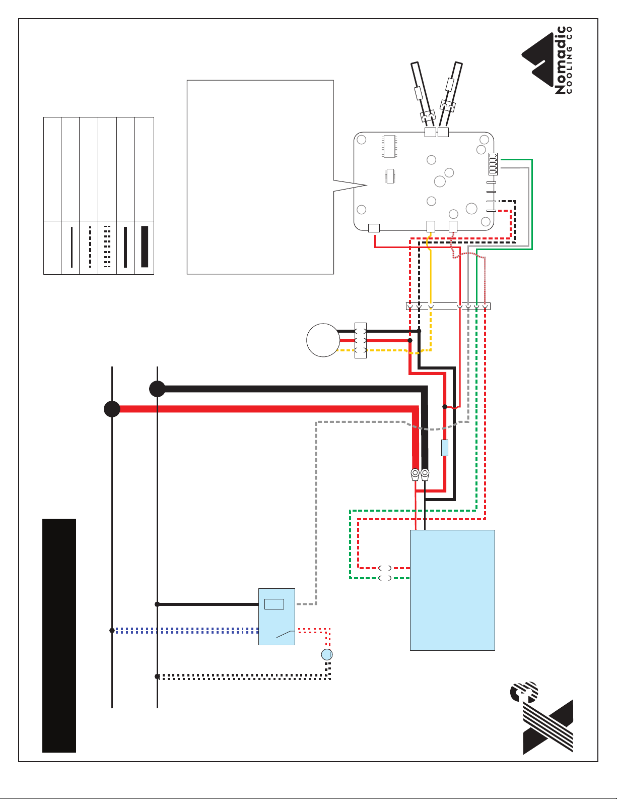
Electrical Wiring Diagram Wire Diameter
24 AWG 0.5mm
18 AWG 1.0mm
15 AWG 1.5mm
12 AWG 2.0mm
10 AWG 2.5mm
Legend
Red(0.5)
White (0.5)
Green(0.5)
Red/White (0.5)
Red(1.0)
Back(1.0)
Yellow(0.5)Yellow(1.0)
Control Panel Connections
J1 1.0 Red - Power supply 12V+
J2 1.0 Back - Power supply 12V-
J5 0.5 Red/White - Compressor start signal
J7 0.5 Back - Air Outlet Temp Sensor
J8 0.5 Back - Inlet Air Temp Sensor
J9 0.5 Red - Voltage monitoring
J10 0.5 White - Fan signal+
J11 0.5 Yellow - Brushless fan speed reguator
C16 0.5 Green - Variable signal of compressor
White(1.0)
Green(1.0)
Red(1.0)

Properly wired LCD Control Panel using included wiring bundle (Part V).
Other manuals for NC-X3
3
Other Nomadic Automobile Accessories manuals


