Latest Revision: 11/5/2019
For questions or help with the installation, please call SDHQ Offroad @ 480-633-2929
Mon.–Fri. 8:00am–5:30pm and Sat. 8:00am–3:30pm Arizona Time. www.sdhqoffroad.com
Page 1of 10
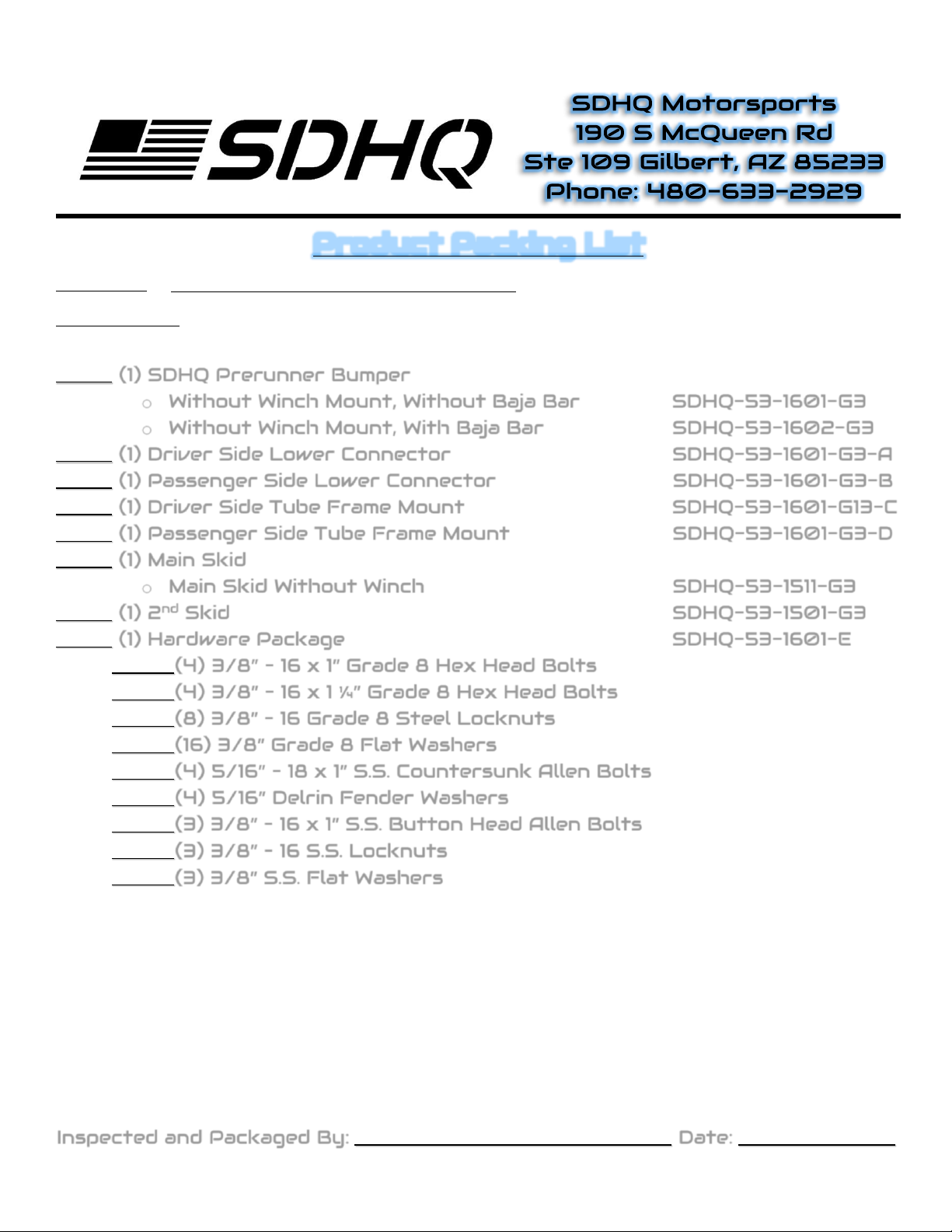
Product Packing List
Product:
SDHQ-53-1601/1602-G3
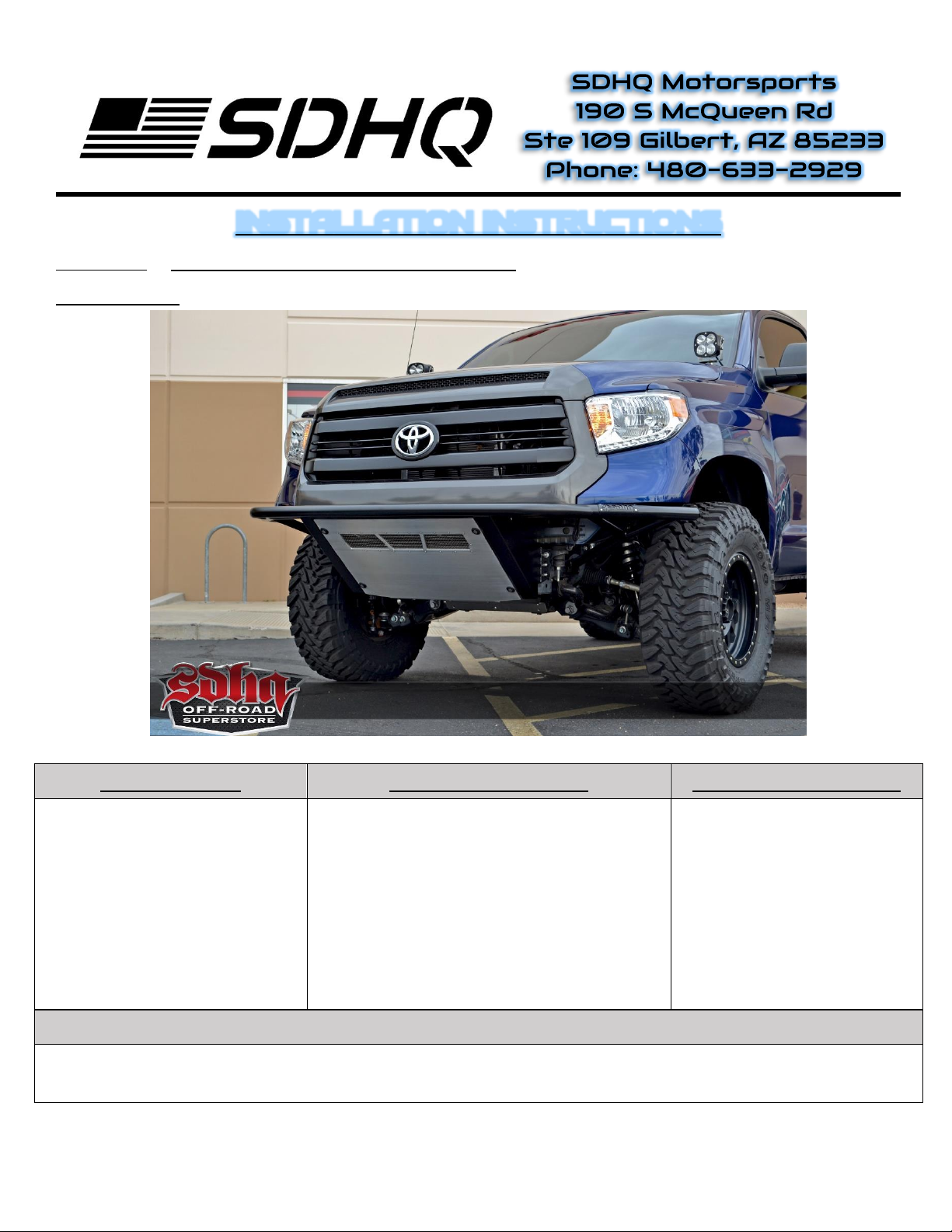
Description: 2007-2020 Tundra Prerunner Bumper
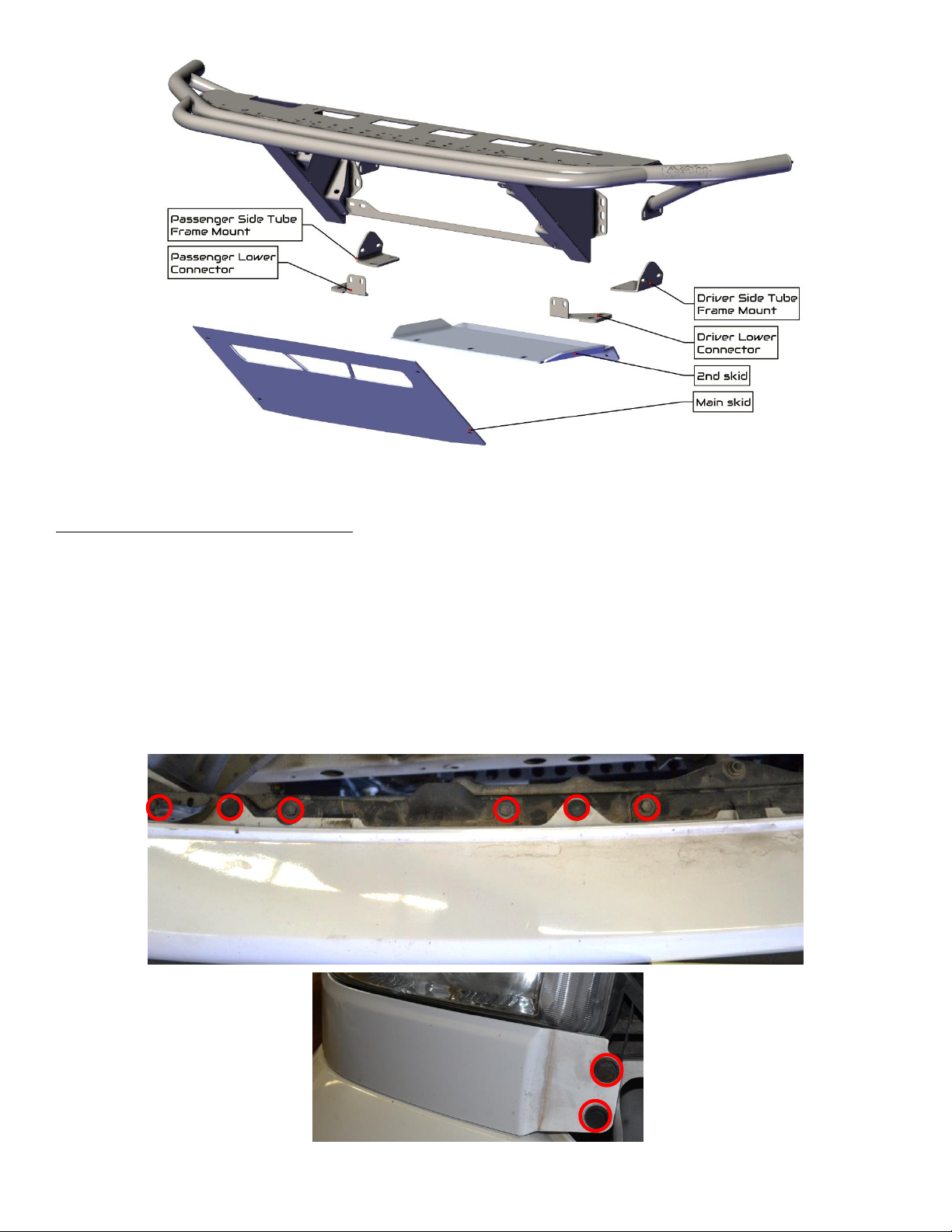
(1) SDHQ Prerunner Bumper
oWithout Winch Mount, Without Baja Bar SDHQ-53-1601-G3
oWithout Winch Mount, With Baja Bar SDHQ-53-1602-G3
(1) Driver Side Lower Connector SDHQ-53-1601-G3-A
(1) Passenger Side Lower Connector SDHQ-53-1601-G3-B
(1) Driver Side Tube Frame Mount SDHQ-53-1601-G13-C
(1) Passenger Side Tube Frame Mount SDHQ-53-1601-G3-D
(1) Main Skid
oMain Skid Without Winch SDHQ-53-1511-G3
(1) 2nd Skid SDHQ-53-1501-G3
(1) Hardware Package SDHQ-53-1601-E
(4) 3/8” – 16 x 1” Grade 8 Hex Head Bolts
(4) 3/8” – 16 x 1 ¼” Grade 8 Hex Head Bolts
(8) 3/8” – 16 Grade 8 Steel Locknuts
(16) 3/8” Grade 8 Flat Washers
(4) 5/16” – 18 x 1” S.S. Countersunk Allen Bolts
(4) 5/16” Delrin Fender Washers
(3) 3/8” – 16 x 1” S.S. Button Head Allen Bolts
(3) 3/8” – 16 S.S. Locknuts
(3) 3/8” S.S. Flat Washers
Inspected and Packaged By: Date: