TJM T13 User manual

FITTING INSTRUCTIONS
Product:
T13 Outback Frontal Protection System
Vehicle:
Mazda BT50
Part No.
070SB13L46E
For product warranty please refer to our website www.tjm.com.au
File: F-5002
Page 1 of 19
25/01/2021
Australian Standards Relating to Installing Vehicle Frontal Protection Systems (VFPS): AS 4876.1-2002
a) Do not attach V.F.P.S. to vehicle using anchorages not intended for this purpose (e.g. engine mounting bolts), other than those
specified by the V.F.P.S. manufacturer in this instruction.
b) Do not use this product for any vehicle make or model other than those specified by the V.F.P.S. manufacturer (as above).
c) Do not remove any plaques or labels from the V.F.P.S.
d) Do not modify the structure of the V.F.P.S. in any way.
•Read instructions fully before commencing fitment.
•Left hand and Right hand components are determined as seated in the
vehicle.
•Check for (and remove) any build up in all captive nuts fitted to the FPS.
•Be aware that a number of government / fleet departments require that the
tow points be painted red.
•Ensure that the “Rated Recovery Label” is affixed alongside the compliance
label, in the driver’s side door jamb.
Bolt tensions
Dia. (mm)
Nm
ft.lbs
Dia. (inch)
Nm
ft.lbs
All bolt tensions
are as follows
unless otherwise
specified.
5
5
4
1/4”
9
7
6
9
7
5/16”
22
15
8
22
16
3/8”
33
27
10
44
32
7/16”
55
43
12
77
57
1/2”
86
66

FITTING INSTRUCTIONS
Product:
T13 Outback Frontal Protection System
Vehicle:
Mazda BT50
Part No.
070SB13L46E
For product warranty please refer to our website www.tjm.com.au
File: F-5002
Page 2 of 19
25/01/2021

FITTING INSTRUCTIONS
Product:
T13 Outback Frontal Protection System
Vehicle:
Mazda BT50
Part No.
070SB13L46E
For product warranty please refer to our website www.tjm.com.au
File: F-5002
Page 3 of 19
25/01/2021
ITEM
NO.
Description
Qty
Part
Number
PARTS LIST
1
Outback FPS
1
F-4843
2
Chassis Mount / Winch Frame
1
F-1287
3
Center Guard
1
F-1570
4
Wing Guard LH
1
F-4972L
5
Wing Guard RH
1
F-4972R
FITTING KIT
6
Chassis Brace LH
1
F-1072L
7
Chassis Brace RH
1
F-1072R
8
Inner Chassis Nut-Plate LH
1
F-1075L
9
Inner Chassis Nut-Plate RH
1
F-1075R
10
Grille Bracket
1
F-1520
11
Winch Control Box Mount
1
88279
12
Wing Guard Bracket
2
F-1845
13
Inner Guard Mount LH
1
F-1059L
14
Inner Guard Mount RH
1
F-1059R
15
Hinged Number-Plate Bracket A
1
F-1372
16
Hinged Number-Plate Bracket B
1
F-1373
17
Fairlead Cover Plate
1
F-1851
18
LED Parker/Indicator
2
92600
19
Fog-Light Blanking Cover
2
92091
20
Fog-Light Washer Plate
4
88057
21
Winch Slot Cover Insert
1
92106
N/A
Wiring Harness
1
92553
ITEM
NO.
Description
Qty
Part
Number
BOLT KIT
N/A
M5 x 0.8 X 20mm Pan Head Screw
2
K0688
N/A
M5 x 0.8 Nyloc Nut
2
K0604
N/A
M5 x Ø10mm Flat Washer
4
K0417
N/A
M6 x 1.0 x 16mm Hex Head Screw
8
K1232
N/A
M6 x 1.0 x 20mm Hex Head Bolt
20
K0550
N/A
M6 x 1.0 Flange Nut
8
K3033
N/A
M6 x 1.0 Nyloc Nut
4
K0605
N/A
M6 x 1.0 Hex Nut
2
K0584
N/A
M6 Spring Washer
16
K0915
N/A
M6 x Ø12.5mm Flat Washer
8
K0897
N/A
M6 x Ø18mm Flat Washer
20
-
N/A
M6 x Ø23mm Flat Washer
6
-
N/A
M8 x 1.25 x 30mm Hex Head Bolt
2
K0554
N/A
M8 Spring Washer
2
K0620
N/A
M8 x Ø24mm Flat Washer
2
-
N/A
M10 x 1.25 x 30mm Hex Head Screw
8
K0564
N/A
M10 x 1.25 x 35mm Hex Head Bolt
2
K0565
N/A
M10 x 1.25 Nyloc Nut
10
K3099
N/A
M10 x Ø30mm Flat Washer
20
WSST-W13
N/A
M12 x 1.25 x 30mm Hex Head Bolt
6
K0569
N/A
M12 x 1.25 x 35mm Hex Head Screw
6
K0570
N/A
M12 x 1.25 x 40mm Hex Head Screw
6
K0571
N/A
M12 x 1.25 Nyloc Nut
12
K1200
N/A
M12 Spring Washer
6
K0977
N/A
1/2" x Ø1-1/4” Flat Washer
30
K0623
N/A
Nylon Plug
4
K0665
N/A
Cable Tie (300mm Long)
2
K1148
22
Hinge Bush
2
K1292
N/A
Rated Recovery Point Label
1
HC0064
N/A
Recovery Point Use Guide
1
F-1768
FITTING INSTRUCTIONS
Product:
T13 Outback Frontal Protection System
Vehicle:
Mazda BT50
Part No.
070SB13L46E
For product warranty please refer to our website www.tjm.com.au
File: F-5002
Page 4 of 19
25/01/2021
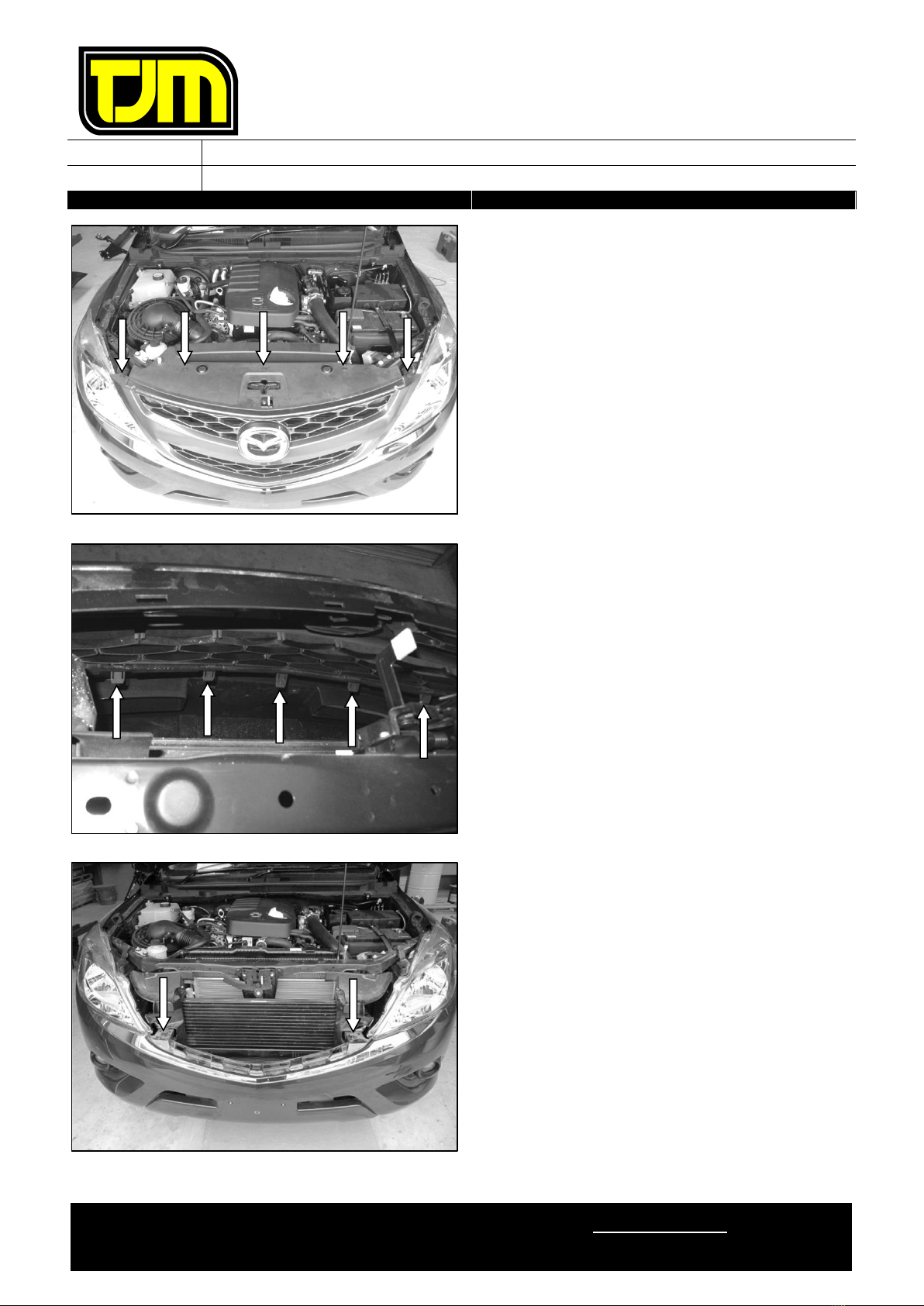
1. Remove (& retain) the number-plate,
discarding the fasteners.
2. Remove (& retain) the clips (5) retaining the
top infill panel & the grille.
3. Remove (& retain) the top infill panel from the
vehicle & carefully set it aside.
4. Behind & along the bottom of the grille,
disengage the clips from the indicated
locations, then remove the grille from the
vehicle & carefully set it aside.
5. Remove (& retain) the fasteners on the
bumper, near the headlights.
FITTING INSTRUCTIONS
Product:
T13 Outback Frontal Protection System
Vehicle:
Mazda BT50
Part No.
070SB13L46E
For product warranty please refer to our website www.tjm.com.au
File: F-5002
Page 5 of 19
25/01/2021
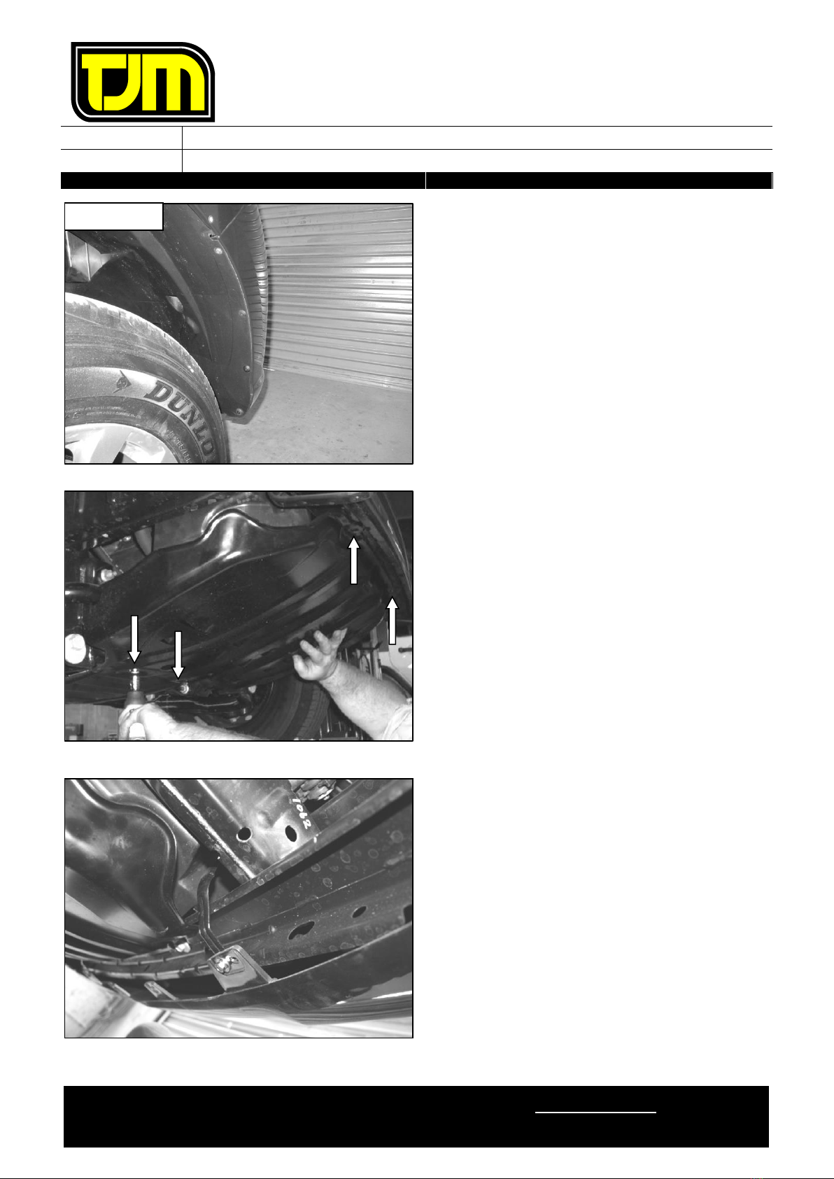
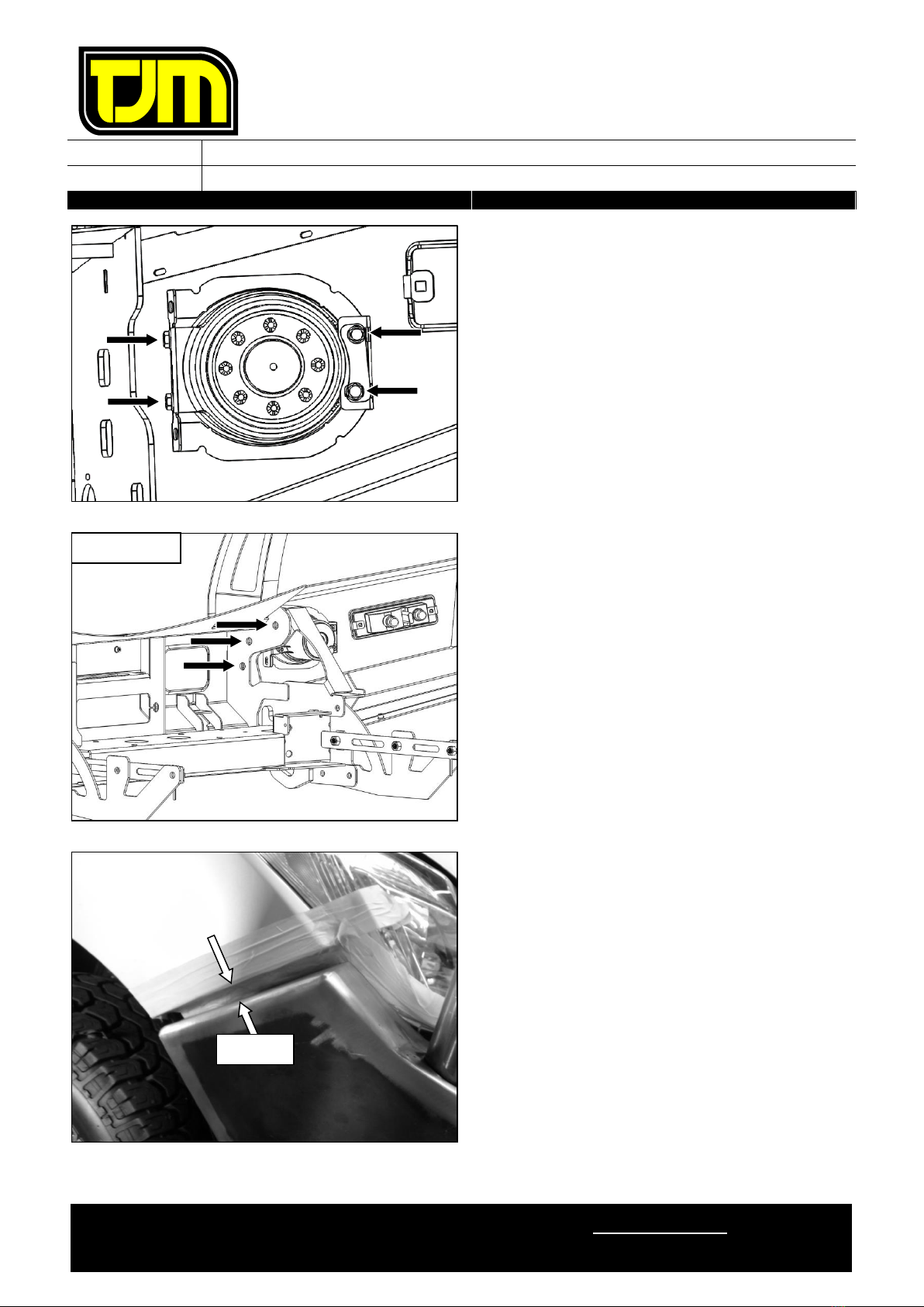
6. On both sides of the vehicle, release the
plastic inner guard from the bumper,
discarding the fasteners.
7. Remove (& retain) the lower steel OE
underbody guard (& associated fasteners)
8. Remove (& discard) the lower bumper skirt.
9. Remove (& discard) the fasteners (4) retaining
the lower edge of the bumper to the support
brackets.
RHS SHOWN
FITTING INSTRUCTIONS
Product:
T13 Outback Frontal Protection System
Vehicle:
Mazda BT50
Part No.
070SB13L46E
For product warranty please refer to our website www.tjm.com.au
File: F-5002
Page 6 of 19
25/01/2021
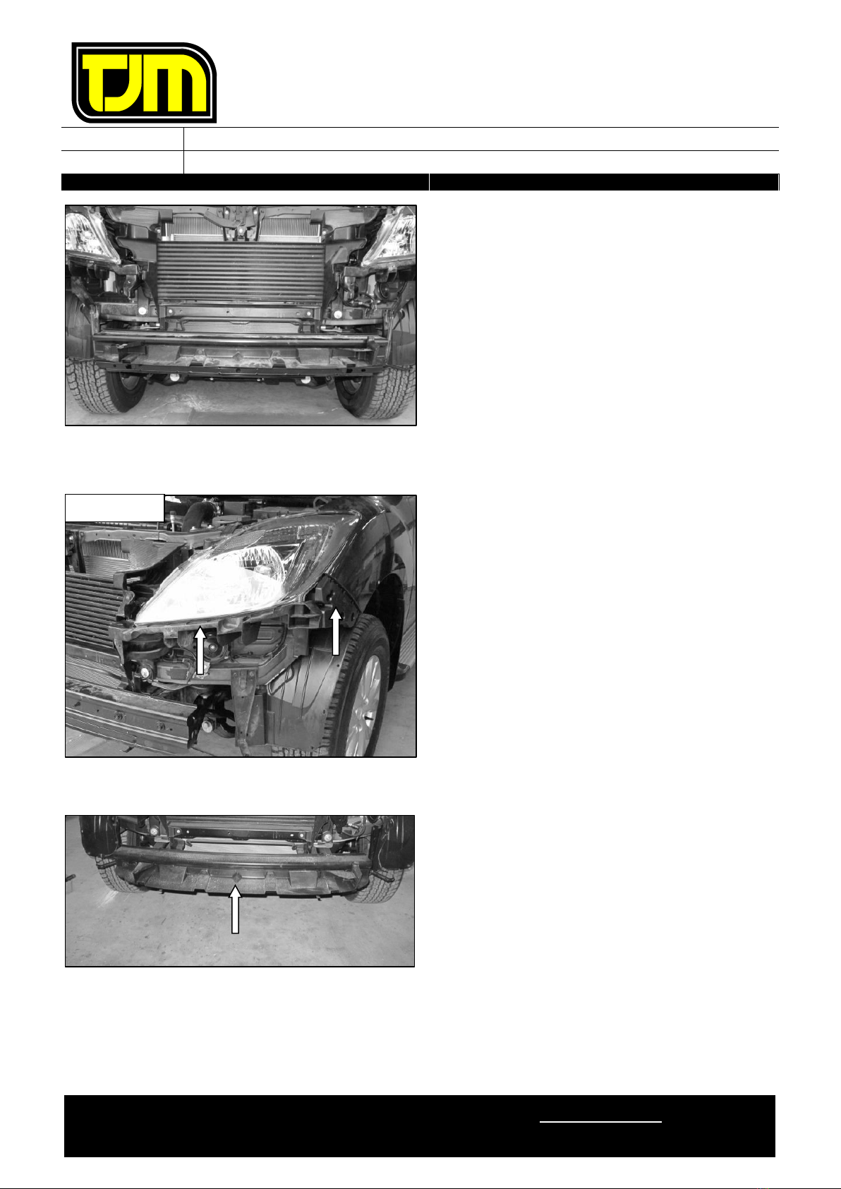
10. If OE fog-lights are installed, disconnect the
wiring harness from the fog-lights.
11. Carefully remove the bumper from the vehicle.
The OE fog-lights & bumper are not
required for the installation of this FPS.
12. Remove (& discard) the indicated plastic
components (& any associated fasteners) from
each headlight.
13. Remove (& discard) the indicated plastic part
(& fasteners) from the front of the intrusion
beam.
LHS SHOWN

FITTING INSTRUCTIONS
Product:
T13 Outback Frontal Protection System
Vehicle:
Mazda BT50
Part No.
070SB13L46E
For product warranty please refer to our website www.tjm.com.au
File: F-5002
Page 7 of 19
25/01/2021
14. Remove (& discard) the front intrusion beam
by:
14.1. removing (& retaining) the front
intrusion beam fasteners (4) from the
indicated locations.
14.2. removing (& discarding) the indicated
clips (2) on the lower plastic air guides.
15. Remove (& discard) the outer bumper support
brackets, retaining the fasteners.
16. Remove (& discard) the inner bumper support
brackets & fasteners.
17. Remove the indicator & park light lamps from
the vehicle’s light housings.
18. Connect the supplied wiring harness inline to
both lamps, then replace the lamps back to
their original locations.
19. Feed the wiring harness through below the
headlights.
20. Check the operation of the indicator/park
lights, then un-plug them.
21. Repeat the previous two steps for the opposite
side of the vehicle.
LHS SHOWN
STEP 14.2
STEP 14.1
RHS SHOWN
STEP 15
STEP 16
FITTING INSTRUCTIONS
Product:
T13 Outback Frontal Protection System
Vehicle:
Mazda BT50
Part No.
070SB13L46E
For product warranty please refer to our website www.tjm.com.au
File: F-5002
Page 8 of 19
25/01/2021
22. Mark the lower air guide as shown, following
the below process:
22.1. Mark a horizontal line on the front face
10mm (approx.) above the rounded
mounting point.
22.2. Mark a vertical line on the side face,
20mm from the flat front face.
22.3. Join the two lines previously created
with a horizontal line on the side face.
23. Following the previously marked trim lines,
trim the left hand lower air guide to shape.
24. De-burr the edges & clean the area/surface of
any swarf/debris.
25. Repeat the previous three steps for the
opposite side of the vehicle.
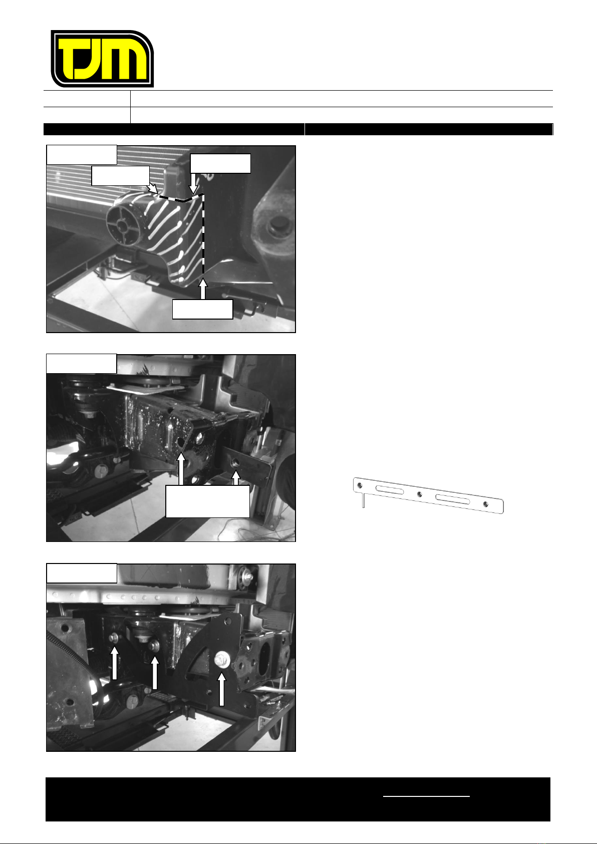
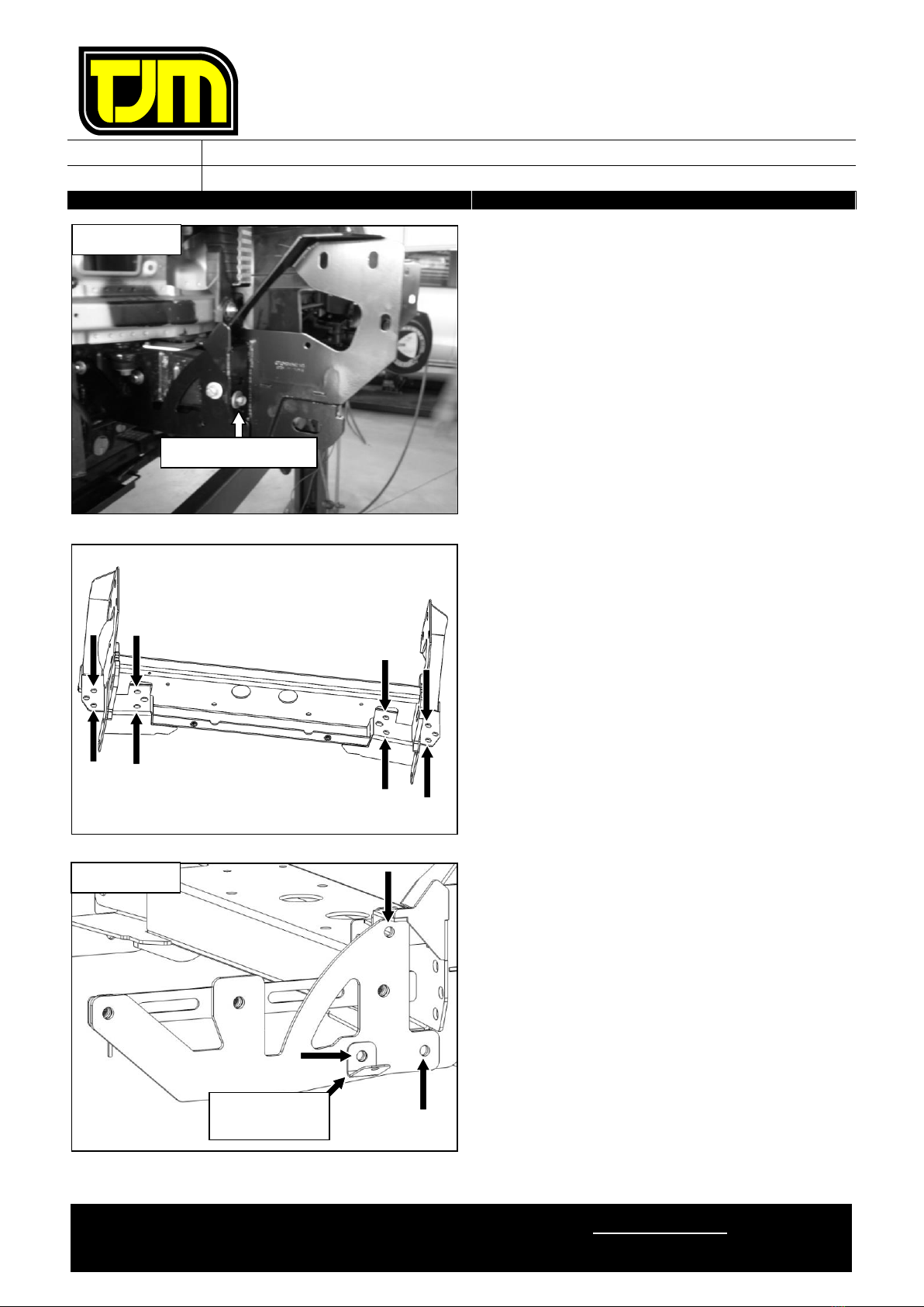
26. With the nuts towards the center of the
vehicle, insert the inner chassis nut-plate into
the large opening in the front of the chassis
rail, having the thin “leg” towards the rear of
the vehicle & touching the bottom inside face
of the chassis rail.
27. Align the holes in the inner chassis nut-plate
with the holes in the chassis rail.
28. Position the chassis brace on the outer face of
the chassis rail (as shown), aligning the
respective holes with the inner chassis nut-
plate, then loosely secure it in place, using
M12 x 1.25 x 40mm hex screws (3), M12
spring washers (3) & 1/2” x Ø1-1/4” flat
washers (3).
29. Repeat steps 26 through to 28 for the
opposite side of the vehicle.
LHS SHOWN
STEP 22.2
STEP 22.3
STEP 22.1
RHS SHOWN
THESE TWO
HOLES ALIGN
RHS SHOWN
FITTING INSTRUCTIONS
Product:
T13 Outback Frontal Protection System
Vehicle:
Mazda BT50
Part No.
070SB13L46E
For product warranty please refer to our website www.tjm.com.au
File: F-5002
Page 9 of 19
25/01/2021
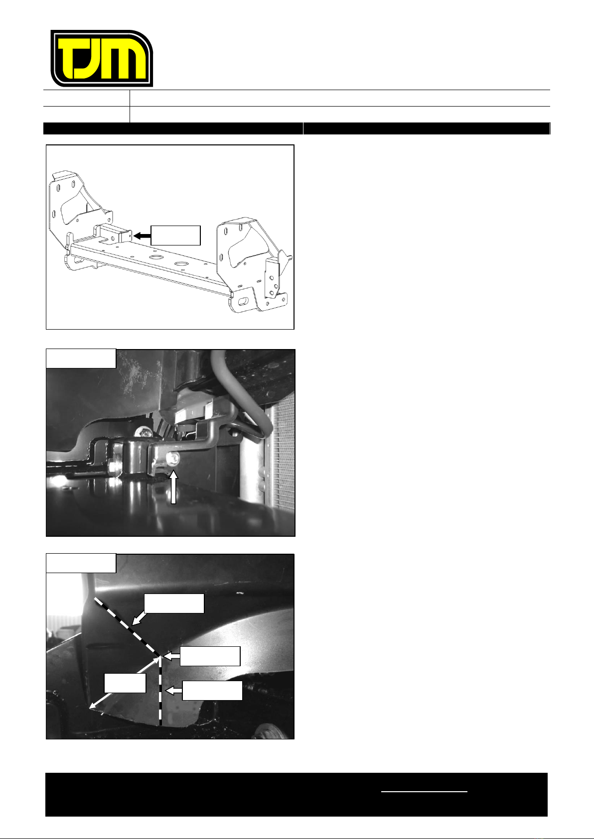
30. Position the chassis mount on the chassis rail
ends (as shown), then loosely secure it in
place through the inner & outer centre
fastening locations (where the fasteners from
step 14.1 were originally removed), using the
fasteners retained in step 14.1.
The chassis mount should fit around
the air guides.
31. Loosely secure the chassis mount in place,
using M10 x 1.25 x 30mm hex screws (8), M10
x Ø30mm flat washers (16) & M10 nyloc nuts
(8).
32. Ensure that the chassis mount is level &
centered to the vehicle. Then tighten the
previously installed chassis mount & chassis
brace fasteners to the relevant torque settings
listed on Page 1.
33. Position the wing guard bracket as shown,
then secure the chassis mount to the chassis
brace at the indicated locations, using M12 x
1.25 x 30mm hex bolts (3), M12 nyloc nuts (3)
& 1/2” x Ø1-1/4” flat washers (6).
34. Repeat the previous step for the opposite side
of the vehicle.
35. Tighten the fasteners installed in the previous
two steps to the relevant torque settings listed
on Page 1.
RHS SHOWN
OUTER LOCATION
RHS SHOWN
WING GUARD
BRACKET
FITTING INSTRUCTIONS
Product:
T13 Outback Frontal Protection System
Vehicle:
Mazda BT50
Part No.
070SB13L46E
For product warranty please refer to our website www.tjm.com.au
File: F-5002
Page 10 of 19
25/01/2021
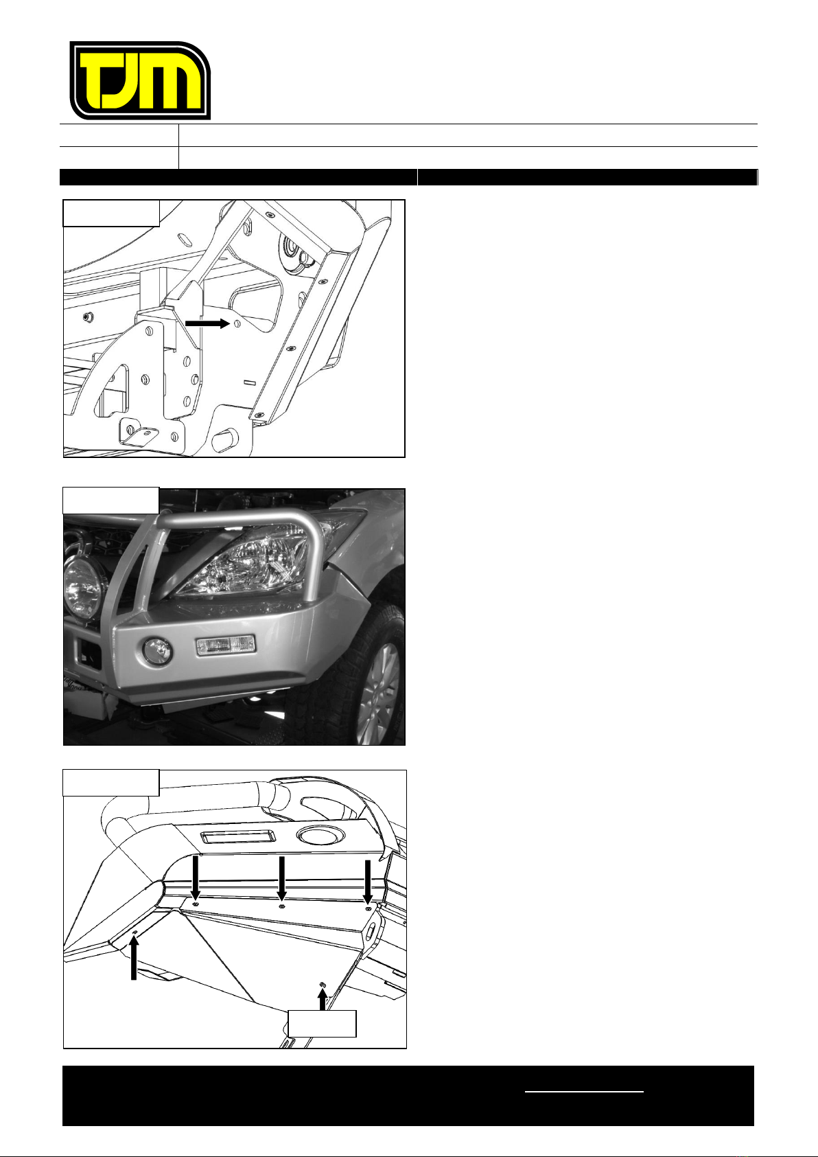
36. Using the indicated hole as a guide, drill a
Ø6mm hole in the trimmed air guides.
37. De-burr the edges & clean the area/surface of
any swarf/debris, then (if applicable) treat any
raw exposed surfaces with a rust preventative.
38. Secure the trimmed lower air guide in place
(as shown), using an M6 x 1.0 x 20mm hex
bolt (1), M6 x Ø23mm flat washer (1), M6 x
Ø18mm flat washer (1) & M6 nyloc nut (1).
39. Repeat steps 36 through to 38 for the
opposite side of the vehicle.
40. Mark the upper air guide as shown, following
the below process:
40.1. Mark a point along the contour line,
65mm from the front lower corner of the
upper air guide.
40.2. From the point previously marked, mark
a line up to the forward edge of the
bend above.
40.3. From the point previously marked, mark
a vertical line down to the lower edge of
the upper air guide.
41. Following the previously marked trim lines,
trim the upper air guide to shape.
RHS SHOWN
STEP 36
RHS SHOWN
65mm
STEP 40.3
STEP 40.2
STEP 40.1

FITTING INSTRUCTIONS
Product:
T13 Outback Frontal Protection System
Vehicle:
Mazda BT50
Part No.
070SB13L46E
For product warranty please refer to our website www.tjm.com.au
File: F-5002
Page 11 of 19
25/01/2021
42. De-burr the edges & clean the area/surface of
any swarf/debris.
43. Repeat the previous three steps for the
opposite side of the vehicle.
44. Position the inner guard mount as shown &
secure it in place by re-installing the fasteners
removed in step 15 to their original location.
45. Using the indicated hole as a guide, drill a
Ø6mm hole in the plastic inner guard.
46. De-burr the edges & clean the area/surface of
any swarf/debris, then (if applicable) treat any
raw exposed surfaces with a rust preventative.
47. Secure the inner guard mount to the plastic
inner guard using an M6 x 1.0 x 20mm hex
bolt (1), M6 x Ø23mm flat washers (2), & M6
nyloc nut (1).
48. Mark the plastic inner guard as shown,
following the below process:
48.1. Mark a horizontal line 70mm below the
indicated edge of the inner guard, across
the flat face of the guard.
48.2. Mark a point on the outer edge of the
plastic inner guard, horizontal with the
noted edge of the inner guard mount.
48.3. Mark a line from the previously marked
point, to the end of the horizontal line
created in step 48.1.
RHS SHOWN
STEP 45
RHS SHOWN
STEP 48.3
EDGE
STEP 48.1
STEP 48.2
LHS SHOWN
70mm

FITTING INSTRUCTIONS
Product:
T13 Outback Frontal Protection System
Vehicle:
Mazda BT50
Part No.
070SB13L46E
For product warranty please refer to our website www.tjm.com.au
File: F-5002
Page 12 of 19
25/01/2021
49. Following the previously marked trim lines,
trim the plastic inner guard to shape.
50. De-burr the edges & clean the area/surface of
any swarf/debris.
51. Repeat steps 44 through to 50 for the
opposite side of the vehicle.
52. Mark the plastic inner guard, following the
below process:
52.1. From where the lower edge of the wheel
arch body guard meets the plastic inner
guard, mark a horizontal trim line along
the plastic inner guard, across to the
first contour.
52.2. 45mm down from the previously marked
trim line, mark a parallel trim line.
52.3. Along the first contour on the plastic
inner guard, mark a trim line, joining the
two previously marked trim lines.
If fitting to a pre-2015 model year face
lift, follow steps 53 to 55. Otherwise,
proceed to step 56.
53. Unclip and discard the trim piece from the
bumper as shown.
RHS SHOWN
BUMPER
45mm
RHS SHOWN
TRIM PIECE

FITTING INSTRUCTIONS
Product:
T13 Outback Frontal Protection System
Vehicle:
Mazda BT50
Part No.
070SB13L46E
For product warranty please refer to our website www.tjm.com.au
File: F-5002
Page 13 of 19
25/01/2021
54. Mark a line and cut along the indicated edges.
Discard the bumper, retaining the grille
support.
55. Install the supplied grille bracket on top of the
plastic grille support with tabs facing the
radiator (as shown). Using fasteners retained
in Step 5, secure the grille bracket and grille
support.
Step 56 applies only to model year 2015
onwards facelifted vehicles.
56. Position the grille bracket as shown (with tabs
facing the front of the vehicle) & secure it in
place, using the fasteners from step 5.
CUT GRILLE SUPPORT
LHS SHOWN
GRILLE
BRACKET
RHS SHOWN
FITTING INSTRUCTIONS
Product:
T13 Outback Frontal Protection System
Vehicle:
Mazda BT50
Part No.
070SB13L46E
For product warranty please refer to our website www.tjm.com.au
File: F-5002
Page 14 of 19
25/01/2021
Steps 57 through to 64 only apply if a
winch is to be fitted. Otherwise, please
proceed to step 65.
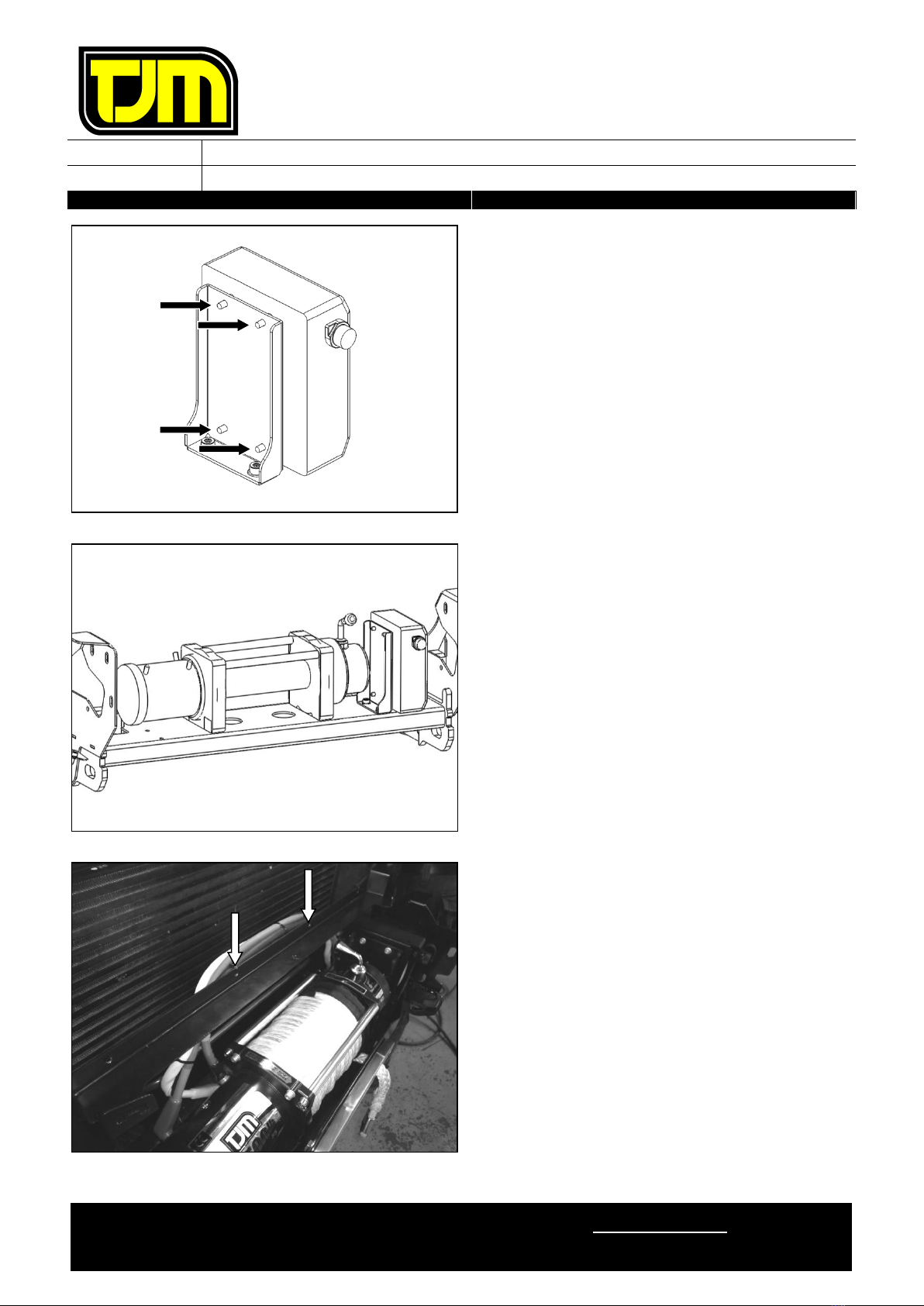
57. Using the fasteners supplied with the winch
control box, secure it to the control box mount
as shown.
58. Locating the winch as shown, refer to the
winch fitting instructions & fit the winch to the
chassis mount/winch frame.
59. Locate the control box as shown & secure it in
place, using M8 x 1.25 x 30mm hex bolts (2),
M8 x Ø24mm flat washers (2) M8 spring
washers (2).
60. Using cable ties, secure the winch cables to
the grille bracket.
61. Check the operation of the winch & ensure
that it is functioning correctly

FITTING INSTRUCTIONS
Product:
T13 Outback Frontal Protection System
Vehicle:
Mazda BT50
Part No.
070SB13L46E
For product warranty please refer to our website www.tjm.com.au
File: F-5002
Page 15 of 19
25/01/2021
It is suggested that the indicated tubing be
manipulated back 5-10mm (approx.) to
ensure that chaffing cannot occur due to
improper use of the winch.
62. Using the fasteners supplied with the winch,
secure the fairlead to the front of the FPS at
the indicated locations.
63. Assemble the number-plate bracket as shown,
using M5 x 0.8 x 20mm pan screws (2),
number-plate hinge bushes (2), M5 x Ø10mm
flat washers (4) & M5 nyloc nuts (2).
64. Secure the hinged number-plate bracket A to
the FPS, using M6 x 1.0 x 20mm hex bolts (2),
M6 x Ø18mm flat washers (2) & M6 spring
washers (2).
TUBING
FITTING INSTRUCTIONS
Product:
T13 Outback Frontal Protection System
Vehicle:
Mazda BT50
Part No.
070SB13L46E
For product warranty please refer to our website www.tjm.com.au
File: F-5002
Page 16 of 19
25/01/2021
Step 65 only applies if no winch has been
fitted. Otherwise, please proceed to step
66.
65. Position the fairlead opening cover as shown &
secure it in place, using M6 x 1.0 x 20mm hex
screws (2), M6 x Ø18mm flat washers (2) &
M6 spring washers (2).
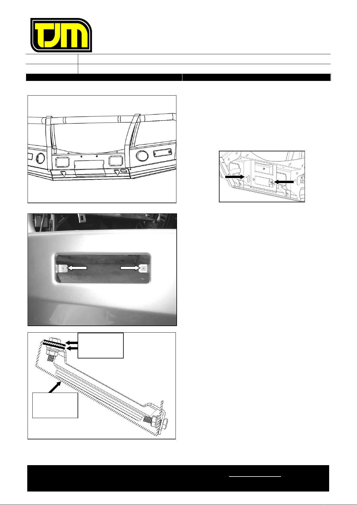
66. Insert the nylon plugs supplied, into the
square cut-outs for the indicator/park lights
(as shown).
67. Separate the indicator / park light body from
the backing plate.
68. Secure the backing plate to the FPS, using the
screws provided with the light assemblies
69. Supporting the backing plate, re-fit (clip) each
indicator / park light body (ensuring that an
adequate seal is achieved).
Ensure that the park light is towards the
outside of the vehicle.
70. Repeat the four previous steps for the
opposite side of the vehicle.
If an optional Foglight Kit has been
purchased, install it now, referring to the
instructions provided with the kit.
Otherwise, follow the below steps to install
the provided Foglight Blanking Covers.
71. Sandwich the foglight mounting bracket
between the Folight Washer Plates.
72. Position the Foglight Blanking Cover as shown
opposite.
FOGLIGHT
MOUNTING
BRACKET
FOGLIGHT
WASHER
PLATES
FITTING INSTRUCTIONS
Product:
T13 Outback Frontal Protection System
Vehicle:
Mazda BT50
Part No.
070SB13L46E
For product warranty please refer to our website www.tjm.com.au
File: F-5002
Page 17 of 19
25/01/2021
73. Using M6 x 1.0 x 20 Hex Head Screws (4), M6
x Ø12.5mm Flat Washers (4) and M6 x 1.0
Flange Nuts (4), secure the Foglight Blanking
Cover to the foglight mounting bracket
74. Repeat the previous three steps for the
opposite side of the vehicle.
75. Re-fit the grille & top infill panel to the vehicle
using the fasteners from step 2.
Ensure that the grille is clipped in place
thoroughly, as per its original
installation (step 4).
76. With the assistance of another person,
carefully lift the FPS into position on the
chassis mount, then loosely secure it in place,
using M12 x 1.25 x 35mm hex screws (6), 1/2"
x Ø1-1/4" flat washers (12) & M12 nyloc nuts
(6) at the indicated locations.
77. Align the FPS to the vehicle, ensuring that
there is an even gap of 20mm between the
ends of the FPS & the wheel arch body guard,
then tighten the fasteners from the previous
step to the relevant torque settings listed on
Page 1.
RHS SHOWN
20mm
FITTING INSTRUCTIONS
Product:
T13 Outback Frontal Protection System
Vehicle:
Mazda BT50
Part No.
070SB13L46E
For product warranty please refer to our website www.tjm.com.au
File: F-5002
Page 18 of 19
25/01/2021
78. Using the indicated hole in the chassis mount
as a template, drill a Ø10mm hole through
both vertical mounts in the FPS.
79. Debur the hole & clean the areas/surfaces of
any swarf/debris, then treat the raw exposed
surfaces with a rust preventative.
80. With the bolt heads on the inside of the
chassis mount, secure through the holes
drilled in step 78, using M10 x 1.25 x 35mm
hex bolts (2), M10 x Ø30mm flat washers (4)
& M10 nyloc nuts (2).
81. Tighten the fasteners from the previous step
to the relevant torque settings listed on Page
1.
82. Connect the previously installed wiring
harnesses to the relevant light assemblies.
83. Check the operation of the light assemblies &
ensure that they are functioning correctly.
84. Position the plastic inner guard inside the
return on the wing.
85. Position the wing guard as shown & secure it
in place using M6 x 1.0 x 20mm hex bolts (4),
M6 spring washers (4) & M6 x Ø18mm flat
washers (4).
86. Secure the wing guard to the wing guard
bracket, using an M6 x 1.0 x 20mm hex bolt
(1), M6 spring washer (1) & M6 x Ø18mm flat
washers (2) & M6 hex nut (1).
87. Repeat the previous two steps for the opposite
side of the vehicle.
LHS SHOWN
RHS SHOWN
RHS SHOWN
STEP 86

FITTING INSTRUCTIONS
Product:
T13 Outback Frontal Protection System
Vehicle:
Mazda BT50
Part No.
070SB13L46E
For product warranty please refer to our website www.tjm.com.au
File: F-5002
Page 19 of 19
25/01/2021
88. Position the centre guard as shown & secure it
in place at the front locations using M6 x 1.0 x
20mm hex bolts (2), M6 spring washers (2) &
M6 x Ø18mm flat washers (2).
89. Re-fit the OE underbody guard as per its
original installation, having the rear of the
centre guard inside the OE underbody guard &
ensuring that the centre guard is secured in
place at the rear, with the OE fasteners from
step 7.
90. Tighten all of the previously installed guard
fasteners to the relevant torque settings listed
on Page 1.
91. Using M6 x 1.0 x 20mm hex bolts (2), M6
spring washers (2) & M6 x Ø18mm flat
washers (2), secure the number-plate in place
to the front of the FPS / number-plate bracket.
92. Ensure that all of the relevant wiring
harnesses are connected & check that the
indicators, park lights, winch, fog-lights, etc
are functioning correctly.
93. Ensure that all of the fasteners are fully
tightened to the appropriate torque settings &
that, as a results of fitting the product, no
vehicle components are crushed or will chafe.
Other manuals for T13
8
This manual suits for next models
1
Table of contents
Other TJM Automobile Accessories manuals


