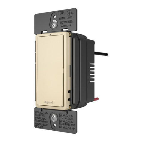
Noon N100 User manual

Installation Guide

Before you get started
If you’ve installed light switches before and are comfortable with high voltage wiring,
installing a Noon™ switch is easy. If not, we highly recommend hiring a professional installer.
Not comfortable with
high-voltage wiring?
Get a Noon-trained professional
installer at noonhome.com/installers.
If you would like to be guided
through the installation experience,
we have just what you need online.
Go to noonhome.com/install.
You’ll have access to:
• Step-by-step video tutorial from a pro
• Mobile-friendly guided installation
• Printable PDF
Guided installation Get a pro
1

This guide is for experienced
DIYers and installers
Get additional help at
noonhome.com/install.
2

In the box
Room Director
Extension Switch
(x2)
Base
(x3)
2-Switch wall plate & mounting plate*
Wall screws (x6)
1-Switch wall plate & mounting plate*
3-Switch wall plate & mounting plate* Wall protector
Apply 1/4 inch below your existing wallplate.
Wall protector
Cleaning cloth
Wire labels and stickers
Phillips screwdriver
Voltage detector
Wire strippers
Tools you’ll need
Wire connectors (x12)
*Noon™Wall Plates and mounting plates are recommended, but not required. Noon switches work with popular
third-party wall plates. You can purchase additional Noon Wall Plates at noonhome.com/store.
3

Need to know
For more information, visit noonhome.com/compatibility.
Compatible bulbs and fixtures
• All residential bulbs including: LED, incandescent,
halogen, fluorescent and CFL bulbs; MLV and ELV fixtures
• Dimmable and non-dimmable bulbs
Noon™replaces light switches
• Works as a single-pole or multi-way switch
• Multi-way configurations support up to four switches per
circuit. Requires all Noon switches on the multi-way circuit.
• Designed for indoor use only
• Works with popular third-party rocker wall plates
Wiring requirements
• Neutral wire required
• Ground wire required
• 120V compatible (not for use with 240V circuits)
TIP: Dimmable bulbs are essential for layered lighting
and highly recommended.
Caution, not compatible with
• Switch-controlled power outlets
• Fans and light fixtures with built-in fans
• Appliances and non-lighting products
See page 14 for wire connector compatibility.
• Hold the wires together and
make sure they are straight.
• Twist the wire connector
firmly clockwise.
Wire connectors provided
Rated for the following limits, per switch
1-gang
Incandescent
and halogen 500W 400W
LED and CFL
MLV fixtures
200W (1.7A)
500VA
200W (1.7A)
400VA
2- and 3-gang

Single-pole switch
One light switch that controls
a light or set of lights.
CONTINUE
STOP
Turn to page 11.
Multi-way switch
Two or more light switches
that control the same light
or set of lights.
Are you replacing a single-pole or multi-way switch?
5

3. Label wires and disconnect old switch
2. Unscrew the old switch1. Turn power o at the circuit breaker
Remove the old switch and identify wires
Confirm that the power
is o from the switch.
We recommend you apply the labels before detaching the wires
from the old switch.
NOTE: Use the single-pole wire labels in the box.
Use the Noon™wall protector
to prevent wall scung.
Ground and neutral wires are required. If you do not
have ground and neutral wires, the Noon switch is not
compatible. Contact us at noonhome.com/contact
to learn about your options.
6

NOON BASE WIRES
Ground (green)
Line/Load (black)
Line/Load (black)
Neutral (white)
WALL WIRES
Ground
Line
Load
Neutral
1. Install the Noon mounting plate 2. Hang the Noon Base from the mounting plate
Install Noon™
Make sure the hooks are
facing out and upwards.
Look for the “Top” indicator.
NOTE: Noon wall and
mounting plates are
recommended, but
not required.
Line and load wires on the Noon
Base are interchangeable.
NOTE: Wire colors in your
switch box may be dierent
from the wire colors shown here.
To free up your hands for
wiring, hang the Noon Base
with the wires near the top
on the mounting plate.
3. Connect wires to the Noon Base
Connecting the Neutral or Ground
wire from the wall to the Line or
Load wire on the Noon Base may
damage the product.
7

4. Install Noon Base
Push the Noon Base into the
switch box and press down
into place.
TIP: Make sure wires are out
of the way before installing.
Repeat previous steps for any
other switches in this box.
Press the corners and along
the edges of the wall plate
to snap it into place.
5. Install the Noon Wall Plate
8
1
2
6. Turn the Noon switch ON before installation
Remove the sticker on
the back before installing.
ON
OFF
(Serial label)
Turn Switch ON
before installation
7. Install Noon switch into the base
Install any other Noon
switches you have for this
room before continuing.
If you need to remove a
switch, pull from the top
and bottom.

Check installation
9
If lights do not
turn on or o, visit
noonhome.com/troubleshoot
for help.
1. Turn power on at the circuit breaker 2. Click switch to turn lights on and o

You can download the Noon App
on your iOS or Android device.
You’re done with installation.
Use the Noon App to complete setup.
10

Noon™switches can replace
multi-way switches. Noon
supports up to four switches
controlling the same light. All
of the switches on a multi-way
need to be replaced.
For full multi-way installation instructions,
go to noonhome.com/multiway.
Installing a multi-way switch
11

Noon switches work as 3-way or 4-way switches. They are wired in parallel. Ground and
neutral wires are required. Use the multi-way wall stickers and wire labels in the box.
Multi-way wiring diagram
Traveller Traveller
Traveller
Line/Load
Line/Load
Line/Load
Line/Load
Line/Load
Line/Load
Traveller
Load
Line
12

13
Resources
For guided installation, visit noonhome.com/install.
To book a Noon-trained installer, visit noonhome.com/installers.
For help troubleshooting your install, visit noonhome.com/troubleshoot.

Warranty
One year warranty included.
Details available at noonhome.com/warranty.
Input: 120 VAC, 60 Hz, 5.5 A max.
Output: 5.2 VDC, 1.4 A
14
This equipment has been tested and found to comply with the limits for a Class B
digital device, pursuant to Part 15 of the FCC Rules. These limits are designed to
provide reasonable protection against harmful interference in a residential
installation. This equipment generates uses and can radiate radio frequency energy
and, if not installed and used in accordance with the instructions, may cause harmful
interference to radio communications. However, there is no guarantee that
interference will not occur in a particular installation. If this equipment does cause
harmful interference to radio or television reception, which can be determined
by turning the equipment o and on, the user is encouraged to try to correct the
interference by one or more of the following measures: (1) Reorient or relocate the
receiving antenna. (2) Increase the separation between the equipment and receiver.
(3) Connect the equipment into an outlet on a circuit dierent from that to which
the receiver is connected. (4) Consult the dealer or an experienced radio/TV
technician for help.
This equipment complies with FCC radiation exposure limits set forth for an
uncontrolled environment. This equipment should be installed and operated
with minimum distance 20cm between the radiator & your body.
Wire connector compatibility: Make sure the wall wires are stripped to 7/16”.
Use with a minimum of two 16AWG wires or a maximum of three 12AWG wires.
Use with copper wires only. (Base wires are 16AWG copper.)
Covered by one or more Patents. View Acknowledgements online.
Details at noonhome.com/legal.
Apple®, the Apple logo, iPhone®, and iPod touch are trademarks of Apple Inc.,
registered in the U.S. and other countries. App Store is a service mark of Apple Inc.,
registered in the U.S. and other countries.
IOS®is a trademark or registered trademark of Cisco in the U.S. and other countries
and is used under license.
Android®is a trademark of Google Inc.
Model numbers: Noon Room Director (N100), Noon Extension Switch (N130),
Base (N190), Noon wall plate (Wall Plate)

This manual suits for next models
2
Table of contents
