Noraxon Ultium EMG System User manual

Insole Smart Lead Quick Start Guide
1
(Rev A)
Ultium Insole
Quick Start
Guide
Insole Smart Lead Quick Start Guide
2
(Rev A)
Welcome from Noraxon
Congratulations on acquiring your new Ultium Insole System!
This guide will provide you with step by step instructions on how to install your new
hardware and software, adjust device settings, and record your first data set.
Let’s begin by walking through how to install your new hardware.
Note: This is not meant to be a complete manual, but a guide to help you get started with your system. For
more detailed instructions on operating the Ultium system and its features please refer to the complete
Ultium EMG User Manual, also included with your system.
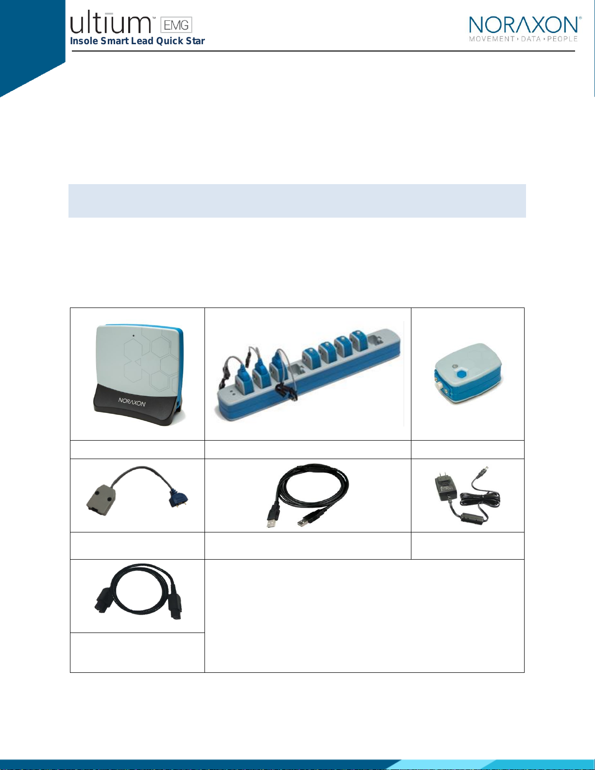
1 System Unboxing
The Ultium Insole system is packed within a reinforced padded box for storage and protection during
transport. Upon arrival, carefully remove all contents and verify the following components are present.
Contents will vary depending on the purchased package.
Figure 1 - Ultium Receiver (part
#880)
Figure 2 - EMG Sensor Docking Station (part #883
Figure 3 - EMG Sensor (part
#810)
Figure 4 - Ultium Insole Smart Lead
(part # 826)
Figure 5 - A to B USB Cable (part #CBL2)
Figure 6 - EMG Sensor
Charger Power Source (part
#PSU1)
Your system may differ depending on the number of sensors included with your
shipment, quantities of EMG sensors, EMG SmartLeads Sensor Docking
Stations, and Docking Station Cables.
Additional items that may be included with your Ultium System include:
•Double side tape samples (part #842C)
•Sample electrodes (typically dual electrodes (part #272)
•Ultium User Manual (part #P-8808)
Figure 8 –Sensor Docking Station
to Ultium Receiver cable (part#
CBL34)
Insole Smart Lead Quick Start Guide
3
(Rev A)
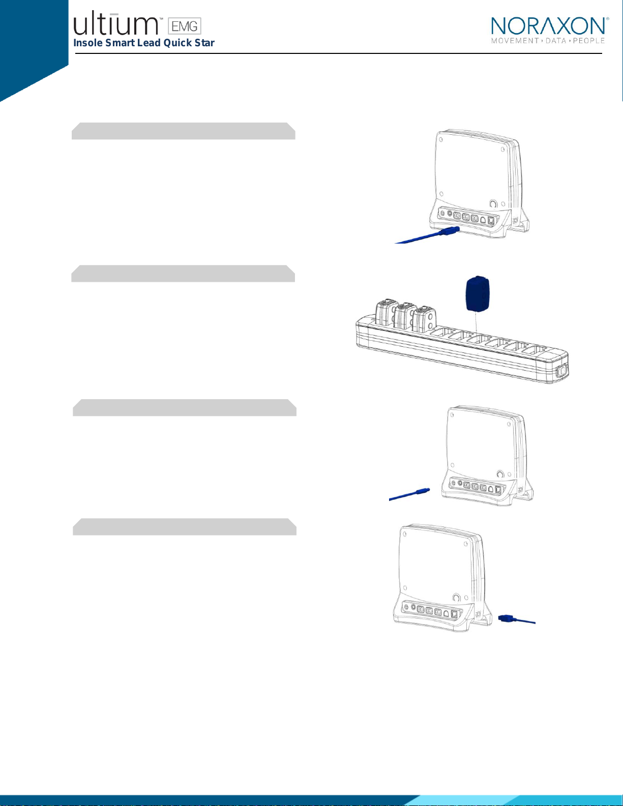
2 Hardware Installation
2.1 Hardware Setup Instructions
Step 1
Insert the USB-B (smaller) end of the USB
cable (CBL2) into the USB connector on the
rear of the Ultium Receiver (880).
Insert the opposite end of the USB cable into
an available USB port on the computer.
Step 2
Insert the EMG probes into the Sensor Docking
Station (883).
Step 3
Insert the power supply (PSU1) barrel
connector into the jack of the Ultium Receiver.
Step 4
Connect the Receiver to the Sensor Docking
Station (883). This will charge the sensors

Insole Smart Lead Quick Start Guide
4
(Rev A)
Step 5
Connect the Insole SmartLead (826) to the
Ultium Sensor (810).
The Ultium Sensor will blink purple after the
SmartLead is detected.
Step 6
Connect the Insole Sensor (826x) to the Insole
SmartLead (826)

Insole Smart Lead Quick Start Guide
5
(Rev A)
3 Installing the Companion Software - myoResearch™ 3
To utilize the full functionality of the Ultium Insole system, and ensure the system has updated drivers,
Noraxon’s myoResearch 3 (MR3) needs to be installed on the computer.
3.1 Software Installation
Within the package the Ultium Insole system was shipped in, there is a USB flash drive containing the
latest myoResearch 3 software.
1. Insert the MR3 USB flash drive into the PC
2. A menu will automatically pop up
3. Click on the Noraxon installation file and follow the Wizard’s instructions
4. After installation, an icon will be created on the desktop
3.2 Companion Software Activation
The installed companion software must be activated before unrestricted use is possible.
1. Open MR3
2. A dialog box will indicate how many more times MR3
can be opened
3. Click on “Activate”
4. Enter the License ID provided on your USB flash drive
and press “OK”
- Continued on next page -
5. If you have an internet connection, click Activate by
Internet for immediate activation
6. Alternatively, email the provided activation ID to
activation@Noraxon.com Noraxon Support will email
or respond by phone with the Activation Code. Enter
the provided Activation Code to remove any restrictions on use.

Insole Smart Lead Quick Start Guide
6
(Rev A)
4 Configuring the Hardware
Step 1
Open MR3, typically listed under Noraxon ->
MR3
Click on the Hardware Setup button in the
upper right-hand corner.
Step 2
Select the Ultium icon, within the ‘New Device’
column, and click on the Insert button.
Note: Make sure the Receiver is connected to
the USB port of the computer via USB Cable
(CBL2).
Step 3
The Ultium Settings dialog will appear as shown.
Within the ‘Settings Tab’, select the desired
collection Sampling Rate.
If using MyoSync, check the Use Noraxon
MyoSync checkbox (see the Ultium EMG User
Manual for more information).
Select a RF Network from the RF Network list. In
most cases the default “1” will work. However, if
using multiple Ultium systems they must be
placed on separate networks.
Note: Firmware updates for the Receiver will be
indicated here, if they are required.
Insole Smart Lead Quick Start Guide
7
(Rev A)
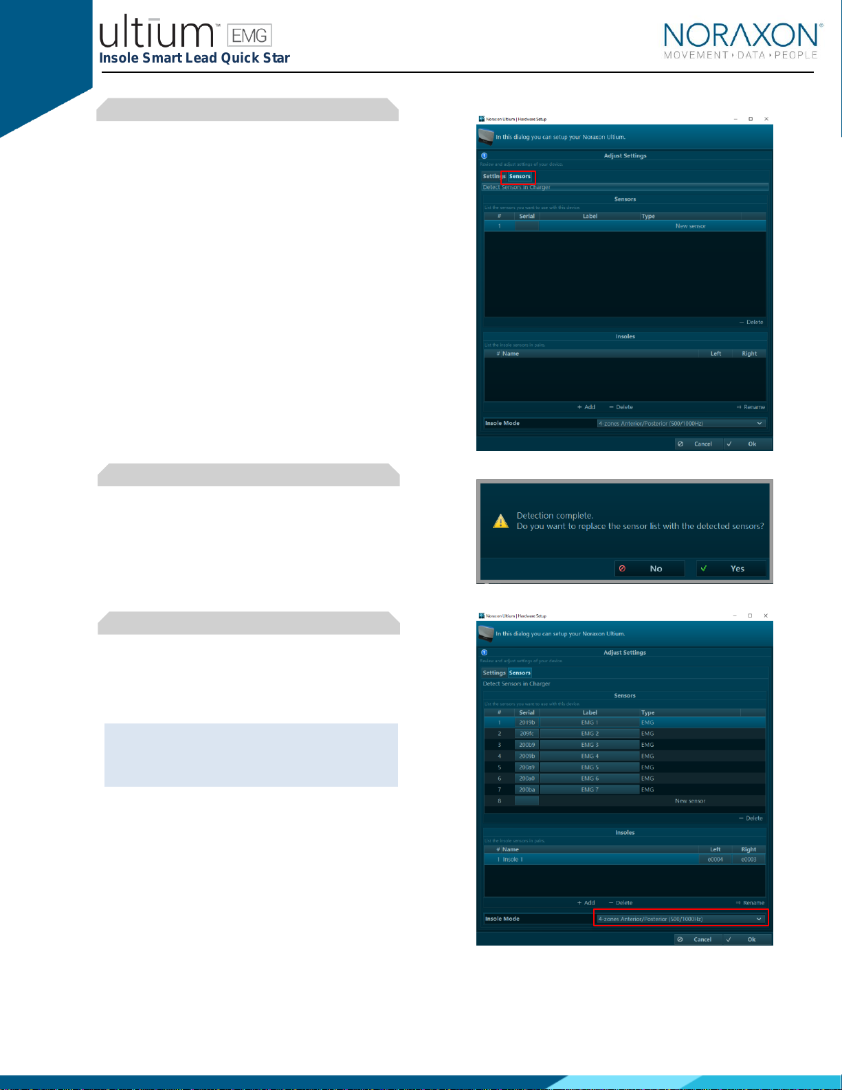
Step 5
Click the Sensors Tab.
Place all Ultium Sensors into the chargers and
attach the chargers to the Ultium Receiver.
Attach the Insole Smart Leads to the Ultium
sensor.
Click Detect Sensors in Charger to load all
serial numbers into the MR3 software.
Step 6
After detection is complete, click Yes to replace
all existing sensor serial numbers associated
with this device.
Step 7
Select the Insole Mode
Click on OK (in the bottom of the dialog box)
when done.
Note: Sensor serial numbers appear in the
order that they are placed in the charging doc,
starting at the end with the LEDs (opposite of
the charging port).
Insole Smart Lead Quick Start Guide
8
(Rev A)
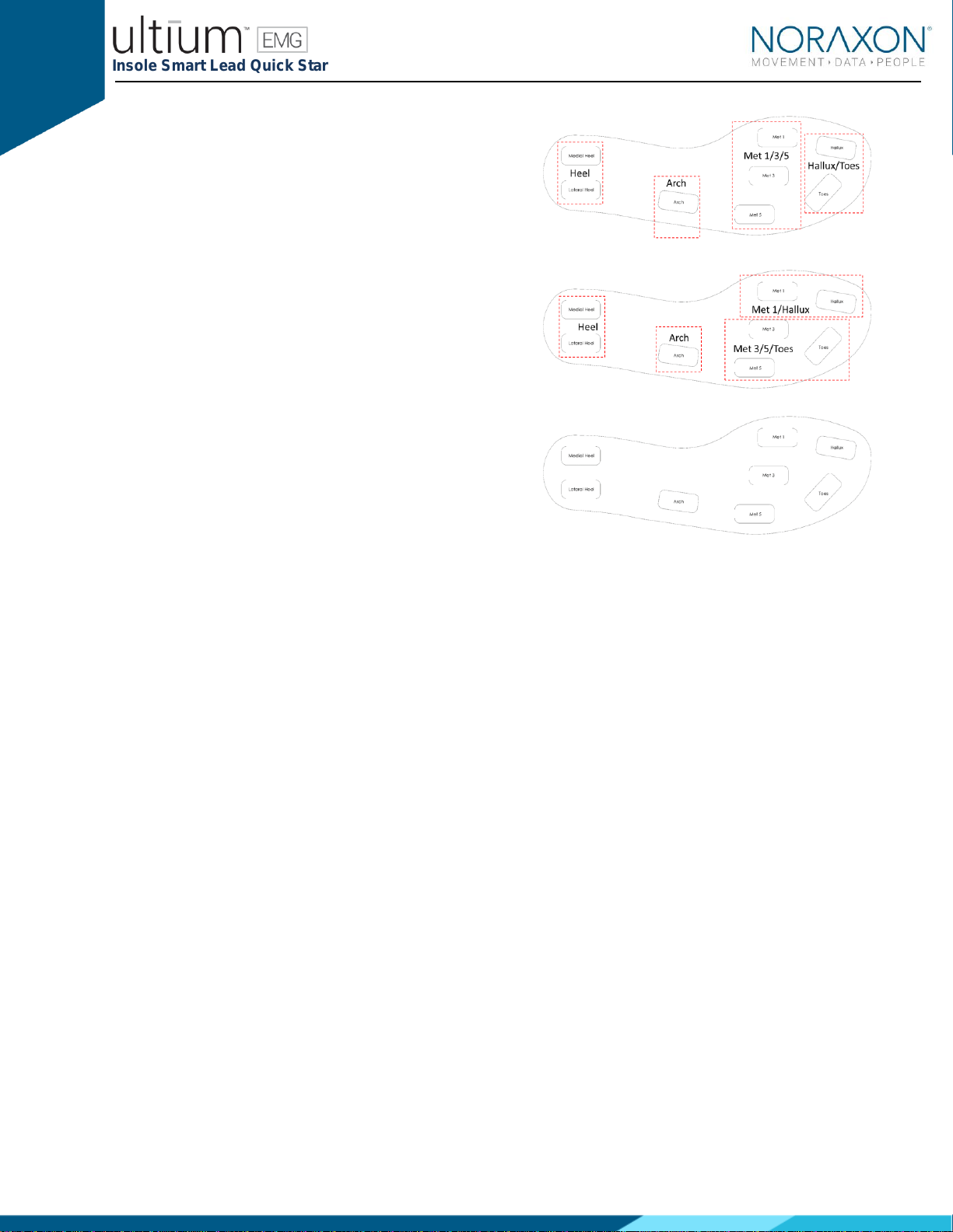
4 Zone Anterior/Posterior
Each zone shown by the red outline is an
average of the sub-zones.
Example
Heel = average of the Medial and Lateral heel
zones
4 Zone Combined
Each zone shown by the red outline is an
average of the sub-zones.
Example
Heel = average of the Medial and Lateral heel
zones
8 Zones
All 8 zones are captured as individual channels

Insole Smart Lead Quick Start Guide
9
(Rev A)
5 Recording a Measurement
Step 1
Within the Home screen, click on the
myoMUSCLE module icon.
Create a New Subject
Select New Configuration.
Step 2
Insert the devices to be used for the
measurement into the configuration by
dragging a device in from the list of Available
devices.
Continue to the next step by selecting
Measure.

Insole Smart Lead Quick Start Guide
10
(Rev A)
Step 3
Select to Calibrate (normalize) the insole
pressure data to static standing pressure.
Continue to the next step by selecting
Measure.
Step 4
After checking for normal signal display, you
are ready to record a measurement. Select
Record at the top left of the screen and begin
your protocol.
After completing your record, select Stop and
Save. Save the record as the name of your
configuration, or type in a new name. After this,
save your record or Discard & measure
again.

Insole Smart Lead Quick Start Guide
11
(Rev A)
6 Viewing a Record
To view a previously recorded record, select the Database tab. Records are organized by Project and
Subject name. Double click on the record of interested to open the record in the Viewer tab.
7 Further Use Features of MR3
There are many additional features built within MR3. Such as:
•COP analysis
•Temporal gait parameters
•Customized reporting
•Exporting (and importing) of data
To learn more about the features available to you through the system(s) you have purchased, refer to the
MyoResearch User Manual and the corresponding Hardware User Manual for this device. If for any
reason you find our support content to be insufficient for your needs, please reach out to our support
team directly by submitting a support request on our website.
8 Insole Sizing
Size Conversion
Insole Size
EU Size
US Mens
US Womens
Small
36-38
5-7.5
Medium
39-41
6-7.5
8-10.5
Large
42-44
8-10.5
11-13
X-Large
45-47
11-13
Insole Dimensions
Insole Sensor Sizes
Length
Forefoot
Width
Heel Width
Thickness
Weight
mm
mm
mm
mm
g
Small
234
89
64
3.5
24
Medium
249
97
64
3.5
26
Large
265
97
64
3.5
30
X-Large
289
99
64
3.5
33

Insole Smart Lead Quick Start Guide
12
(Rev A)
9 Insole Care and Cleaning
Extra care must be taken when cleaning the insoles.
•Clean with isopropyl alcohol or disinfectant wipes.
•Dampen the surfaces and do not allow solution into the vent holes.
Each insole has 5 vent holes which must remain open and free of any debris. The insoles are
ambidextrous and can be placed with the vent holes facing up or down.
Other manuals for Ultium EMG System
5
Table of contents
Other Noraxon Personal Care Product manuals


