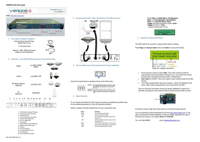
Noraxon Ultium EMG System User manual

Ultium EMG Hardware User Manual
1
(Rev J)
Ultium™ EMG System
Sensor and
Sensor and Sensor and
Sensor and
Receiver U
Receiver UReceiver U
Receiver User Manual
ser Manualser Manual
ser Manual

Ultium EMG Hardware User Manual
2
(Rev J)
Table of Contents
Table of ContentsTable of Contents
Table of Contents
1
General Warnings and Cautions ...................................................................................................................... 5
1.1
Risks and Benefits .................................................................................................................................... 5
1.2
Safet Information Summar ................................................................................................................. 5
2
Introduction .......................................................................................................................................................... 6
2.1
Brief Description: ....................................................................................................................................... 6
2.2
Device Safet Categories ........................................................................................................................ 6
2.3
Intended Use .............................................................................................................................................. 6
2.4
Contraindications...................................................................................................................................... 7
3
Definitions ............................................................................................................................................................ 8
3.1
Graphic S mbols and Meaning .............................................................................................................. 8
3.2
Glossar of Terms .................................................................................................................................... 9
4
Product Information ......................................................................................................................................... 10
4.1
Model Designation .................................................................................................................................. 10
4.2
Product Versions and Configurations ................................................................................................. 10
4.3
Software Requirements ......................................................................................................................... 10
5
Setting up the Hardware .................................................................................................................................. 11
5.1
S stem Unboxing .................................................................................................................................... 11
5.2
Ultium Receiver Overview...................................................................................................................... 13
5.3
Ultium EMG Sensor Overview............................................................................................................... 14
5.4
Hardware Setup Instructions ................................................................................................................ 15
5.5
Installing the companion Software – m oResearch™ 3 .................................................................. 16
5.6
Configuring the Hardware ..................................................................................................................... 17
5.7
Configuration using Ultium Smart Leads ........................................................................................... 19
6
Basic Operation Instructions .......................................................................................................................... 20
6.1
Safet Information Summar ............................................................................................................... 20
6.2
Ensure the Ultium Sensor is in Measurement Mode ....................................................................... 20
6.3
Attach the EMG Sensor with EMG Smart Lead Sensor to a Patient or Subject .......................... 20
6.4
Recording a Measurement ................................................................................................................... 21
6.5
Enter into the Measurement Screen ................................................................................................... 21
6.6
Check for Normal Signal Displa with Interface to a PC ................................................................. 22
6.7
Check Signal Qualit ............................................................................................................................... 22
6.8
Record Signal as Desired ...................................................................................................................... 24
6.9
Shutdown after Use ................................................................................................................................ 24
6.10
Storage and Protecting Between Use ................................................................................................. 24
7
Additional Ultium EMG Settings and Features ............................................................................................ 25
7.1
Ultium Receiver S nchronization ......................................................................................................... 25

Ultium EMG Hardware User Manual
3
(Rev J)
7.2
32 Channel Operation ............................................................................................................................ 26
7.3
Lossless Data Recover ........................................................................................................................ 26
7.4
Ultium Internal Inertial Measurement Unit (IMU) .............................................................................. 27
7.5
Signal Processing for Amplitude Normalization ............................................................................... 29
8
Maintenance ...................................................................................................................................................... 30
8.1
Consumable Items ................................................................................................................................. 30
8.2
Maintenance b Users ........................................................................................................................... 30
8.3
Companion Software Updates ............................................................................................................. 32
8.4
Device Software (firmware) updates .................................................................................................. 32
8.5
Batter Replacement .............................................................................................................................. 32
9
Troubleshooting, Fault Diagnosis .................................................................................................................. 34
9.1
Troubleshooting Chart ........................................................................................................................... 34
9.2
Website Link to FAQ ............................................................................................................................... 34
9.3
Radio Considerations ............................................................................................................................. 35
9.4
Setting the RF Network .......................................................................................................................... 35
10
Support, Service, and Repair ..................................................................................................................... 36
10.1
Submitting Technical Support Requests ............................................................................................ 36
10.2
Returning Equipment ............................................................................................................................. 36
11
Taking Product out of Operation .............................................................................................................. 37
11.1
Disposal of Equipment and Batteries ................................................................................................. 37
12
Technical Information ................................................................................................................................ 38
12.1
Theor of Operation ............................................................................................................................... 38
12.2
Electro-Magnetic Compatibilit Tables............................................................................................... 38
13
Appendices ................................................................................................................................................... 42
13.1
Appendix A – Product Specifications ................................................................................................. 42
13.2
Appendix B – Use of Disposable Electrodes ..................................................................................... 45
13.3
Appendix C – Radiation Exposure Information Regarding Use of EMG Sensors ....................... 47
13.4
Appendix D – Radio Regulator Statements ..................................................................................... 48
13.5
Appendix E – Ultium SmartLead Specifications ............................................................................... 49
13.6
Appendix F – Ultium Analog Output Module (Model 881) .............................................................. 51

Ultium EMG Hardware User Manual
4
(Rev J)
M
-
--
-
Manufacturer:
::
:
Noraxon U.S.A. Inc.
15770 North Greenwa -Ha den Loop, Suite 100
Scottsdale, AZ 85260
Tel: (480) 443-3413
Fax: (480) 443-4327
Email:
info@noraxon.com
Support Email:
support@noraxon.com
Web Site:
www.noraxon.com
P - Authorized European Representative:
tive:tive:
tive:
EC REP Advena Limited, Tower Business Centre, 2nd Flr., Tower Street, Swatar,
BKR 4013 alta
Website: http://www.advenamedical.com
CE Marking and Notified Body:
::
:
Clearance to market this product (#810) in the European Communit has been certified b Notified
Bod #2797, British Standards Institution (BSI)
2797
No part of this document ma be copied, photographed, reproduced, translated, or reduced to an
electronic medium or machine-readable form without prior written consent of Noraxon U.S.A. Inc.
Noraxon and m oRESEARCH are registered trademarks and the Noraxon logo, m oANALOG, m oFORCE, m oMETRICS, m oMOTION,
m oMUSCLE, m oPRESSURE, m oVIDEO, m oSYNC, NiNOX, TRUs nc and Ultium are common-law trademarks of Noraxon U.S.A., Inc. All other
trademarks are the propert of their respective owners. ©2018, all rights reserved.

Ultium EMG Hardware User Manual
5
(Rev J)
1 Genera Warnings and Cautions
1.1 Risks and Benefits
There is no identified risk of ph sical harm or
no identified risk of ph sical harm or no identified risk of ph sical harm or
no identified risk of ph sical harm or injur
injurinjur
injur with use of the Ultium EMG S stem. The benefit
provided b use of the device is the provision of objective measures to assess the severit of
pathological human movement conditions and gauge an subsequent improvement offered b therap ,
training or design changes.
1.2 Safety Information Summary
Cautions
Never use the Ultium S stem on a person with an implanted pacemaker
Never operate the Ultium S stem within 1 meter of an critical medical device
arnings
Do not immerse the EMG Sensors in an water or liquid
Do not drop
Do not use in conditions where the temperature can exceed 55 °C (130 °F)
Do not use the Ultium equipment on individuals undergoing MRI, Electro Surger or
Defibrillation
The Ultium product produces results that are informative, not diagnostic. Qualified individuals
must interpret the results
Attention
The operator must be familiar with t pical characteristics of the signals acquired b the Ultium
equipment and be able to detect anomalies that could interfere with proper interpretation.

Ultium EMG Hardware User Manual
6
(Rev J)
2 Introduction
2.1 Brief Description:
The Ultium S stem for EMG and other biomechanical sensors wirelessl transmits data from the
electrode or sensor site to a desktop receiver.
This wireless transmission concept greatl simplifies the collection of EMG measurements b
eliminating cable connections between the EMG electrodes and EMG amplifier. The small, lightweight
EMG sensors are also beneficial for small subjects like children and small animals.
This unique concept gives the user the flexibilit to operate the Ultium S stem without the traditional
laborator -based measurement limitations. The Ultium S stem is designed to operate an
configuration between 1 and 16 sensors. Multiple Ultium S stems can be used simultaneousl to
increase the configuration to 32 sensors.
The default s stem is equipped with EMG sensors but can be upgraded with other biomechanical
sensors, e.g. goniometers, inclinometers, and foot switches. The EMG sensors can also be activated to
measure IMU data or a combination of EMG with acceleration data. A s nchronization capabilit can be
used to accuratel s nchronize the Ultium S stem to other biomechanical devices.
2.2 Device Safety Categories
The Ultium S stem incorporates the following ratings:
Class II (double insulation) for electrical safet with internal batter power during operation
CISPR 11 Class A radio frequenc compatibilit (ref. Section 17 for details)
Note: The EMISSIONS characteristics of this equipment make it suitable for use in industrial areas and hospitals (CISPR 11 class
A). If it is used in a residential environment (for which CISPR 11 class B is normall required) this equipment might not offer
adequate protection to radio-frequenc communication services. The user might need to take mitigation measures, such as
relocating or re-orienting the equipment.
2.3 Intended Use
Noraxon’s Ultium EMG sensor is intended to measure and quantif muscle biopotential signals
separatel or in combination with other kinematic or kinetic signals. These inter-related measurements
can provide data to assist in understanding movement abnormalities. The s stem is designed as a
diagnostic tool for clinical, investigational and research applications. Additionall , this device is
compliant to the international standard for diagnostic EMG (IEC 60601-2-40).
Intended Users
Researchers or individuals trained in ph sical medicine, ph sical therap , human performance or
ergonomics and who have gained familiarit with the Ultium S stem and its software.
Subject Populations – Medical
Individuals with neurological disorders, ph sical injuries, pre/post-surgical or post stroke conditions.
Subject Populations – Non-medical
Athletes, workers at their work site, subjects in new product trials.

Ultium EMG Hardware User Manual
7
(Rev J)
Common Applications
Gait anal sis; identification of inconsistencies and abnormalities; tracking over time the outcome of
surgical, therapeutic or orthotic interventions; identification of ergonomic stress factors in the
workplace or new product designs.
Suitable Environments
The Ultium S stem is suitable for use in hospitals, clinics, academic laboratories except near active HF
SURGICAL EQUIPMENT or MRI IMAGING EQUIPMENT.
Expected (Essential) Performance
The Ultium S stem (EMG sensor and Receiver) s nchronousl acquires and displa s muscle activit
signals from multiple muscle sites in real time.
Consideration should be given to common place wireless networks that ma be present in the
environment. Under the conditions of excessive wireless communications performance of the Ultium
S stem ma exhibit sluggish (non-real-time) behavior.
Risk-Benefit
There is no identified risk of ph sical harm or injur
no identified risk of ph sical harm or injurno identified risk of ph sical harm or injur
no identified risk of ph sical harm or injur
with use of the Ultium product. The benefit provided
b use of the device is the provision of objective measures to assess the severit of pathological
human movement conditions and gauge an subsequent improvement offered b therap , training or
design changes.
Special Concerns
The Ultium EMG s stem operates b means of microwave radio frequenc transmissions. Certain
(older, vintage model) pacemaker devices ma be susceptible to such microwave transmissions.
Therefore, use of the device is contra-indicated in individuals who have implanted pacemakers.
2.4 Contraindications
Use of the Ultium EMG is contra-indicated in individuals who have implanted pacemakers.

Ultium EMG Hardware User Manual
8
(Rev J)
3 Definitions
3.1 Graphic Symbols and Meaning
The following international icons and s mbols are found on the Ultium enclosures and in this user
manual. Their meaning is described below.
Approval to market this product (#810) in the European Communit was
certified b Notified Bod #2797 BSI.
The device generates radio frequenc energ during operation.
A 5 Volt DC external power source is applied to this connection.
The device is suitable for a direct electrical attachment to the bod .
Read material in the Instruction Manual wherever this s mbol appears.
Identifies the manufacturer of the device.
Identifies the serial number of the device.
Additional information available in a separate document

Ultium EMG Hardware User Manual
9
(Rev J)
3.2 Glossary of Terms
Ultium Receiver
Ultium ReceiverUltium Receiver
Ultium Receiver – A USB-connected Receiver which receives signals from one or more EMG sensors.
Ultium
UltiumUltium
Ultium-
--
-EMG Sensor
EMG SensorEMG Sensor
EMG Sensor -- A small individual radio transmitter t picall worn on the bod used to measure
and transmit bio-potential signals (such as EMG) or motion related signals (such as position or
acceleration). The Ultium S stem can accommodate up to 16 bod worn EMG Sensors in one network.
Ultium
UltiumUltium
Ultium-
--
-EMG
EMG EMG
EMG SmartLead
SmartLeadSmartLead
SmartLead – An accessor sensor that can be connected to an EMG sensor to provide
other biomechanical signals. Examples include force, acceleration, etc.
Ultium
UltiumUltium
Ultium-
--
-EMG Serial Number
EMG Serial NumberEMG Serial Number
EMG Serial Number – A unique five-character tag used to identif each EMG Sensor. The
members of an Ultium network are determined b their serial numbers. Smart Lead T pes are grouped
into a predefined range of serial numbers. Thus, b serial number the Ultium s stem can automaticall
determine the t pe of signal parameter being transmitted from an Sensor in the network.
Multi
MultiMulti
Multi-
--
-Channel Sensor
Channel SensorChannel Sensor
Channel Sensor – Certain Sensor T pes provide more than one signal. Thus, a Multi-Channel
Sensor behaves like two or three standard Sensors. An example is a 3-D Accelerometer that provides
acceleration data for the x, and z directions.
Probe
ProbeProbe
Probe – A generic term for an EMG Sensor.
RF
RFRF
RF – (Abbreviation for Radio Frequenc ) Wireless communication takes place on assigned radio
frequencies or channels. For the Ultium S stem, RF transmissions occur at frequencies between 2.4
GHz and 2.5 GHz. Other wireless s stems including WiFi and Bluetooth commonl operate at the same
frequencies and can be a source of interference.
RF Network
RF NetworkRF Network
RF Network – RF transmissions for the Ultium S stem can be selected to occur on one of 4 different
networks. All networks use frequenc hopping to avoid interference.
RF Traffic
RF TrafficRF Traffic
RF Traffic – The presence of radioactivit present on a given frequenc similar to the number of cars
on an expresswa . Several users (wireless devices) ma be communicating using the same
frequencies. Best operation of the Ultium S stem occurs when the RF Traffic is low.

Ultium EMG Hardware User Manual
10
(Rev J)
4 Product Information
4.1 Model Designation
The basic Ultium S stem consists of three primar components:
Model 880 Ultium Receiver (1 per s stem)
Model 810 EMG Sensor (up to 16 per s stem)
Model 883 EMG Docking Station (up to 2 per s stem)
4.2 Product Versions and Configurations
The model 880 Ultium Receiver can accommodate up to 16 Ultium EMG Sensors. The standard model
810 Sensors contain a 3-axis inertial measurement unit and can be combined with an of the following
SmartLead t pes:
Model 802 Ultium Footswitch
Model 808 Ultium 2D Flexible Axis Goniometer
Model 811 Ultium 3-channel Analog Input Sensor
Model 817 Ultium 3D Accelerometer
Model 820 Ultium 500 LbF Force Sensor
Model 821 Ultium 100 LbF Force Sensor
Model 824 Ultium Local Pressure Sensor
Model 842 Ultium EMG Lead
Model 852 Ultium BioMonitor (ECG and Respiration)
For additional equipment details refer to Section 14 and Appendix E of this User Manual.
4.3 Software Requirements
The Ultium S stem requires software to perform its function, the equipment is offered in combination
with the following computer program packages:
Noraxon m oRESEARCH® (MR3.12 or newer) Software Platform and m oMUSCLE™ Software Module

Ultium EMG Hardware User Manual
11
(Rev J)
5 Setting up the Hardware
5.1 System Unboxing
The Ultium S stem is packed within a reinforced padded box for storage and protection during
transport. Upon arrival, carefull remove all contents and verif the following components are present.
Figure 1 - Ultium Receiver (part #880)
Figure 6 - to B USB Cable (part #CBL2)
Figure 3 - EMG Sensor (part #810) Figure 4 - Ultium EMG Smart Lead (part # 842)
Figure 2 - EMG Sensor Docking Station (part #883)
Figure 5 -
EMG Sensor Charger Power Source
(part #PSU1)

Ultium EMG Hardware User Manual
12
(Rev J)
Your s stem ma differ depending on the number of sensors included with our shipment, quantities of
EMG sensors, EMG SmartLeads Sensor Docking Stations, and Docking Station Cables.
Additional items that ma be included with our Ultium S stem include:
Double side tape samples (part #842C)
Sample electrodes (t picall dual electrodes (part #272)
Ultium User Manual (part #P-8808)
Accessories
If additional accessories have been included, please see Section 14, Appendix E of this User Manual, or
the www.noraxon.com for more information.
Figure 8 – Sensor Docking Station to Ultium
Receiver cable (part# CBL34)

Ultium EMG Hardware User Manual
13
(Rev J)
5.2 Ultium Receiver Overview
The below section will over the ke components of the Ultium s stem receiver, sensor, and charging
dock. Additional information can be found around the indicators and operation of the s stem in the
following sections.
Receiver (Front)
1.
1.1.
1. Status LED
Status LEDStatus LED
Status LED – Indicates the status of the Receiver.
2.
2.2.
2. Charging Dock Port
Charging Dock PortCharging Dock Port
Charging Dock Port – Connects the Sensor Docking Station to
the Receiver for communication.
Receiver (Back)
1.
1.1.
1. Sensor Power Button
Sensor Power ButtonSensor Power Button
Sensor Power Button – Push to toggle power on sensors
inserted into connected chargers.
2.
2.2.
2. Docking Ports
Docking PortsDocking Ports
Docking Ports - Allows docking stations to be connected for
power and data communication to sensors.
3.
3.3.
3. USB Port
USB PortUSB Port
USB Port – USB connection between the computer and receiver.
4.
4.4.
4. Lockstep
LockstepLockstep
Lockstep – Reserved for future use.
5.
5.5.
5. AUX1, AUX2, AUX3
AUX1, AUX2, AUX3AUX1, AUX2, AUX3
AUX1, AUX2, AUX3 – Connect auxiliar accessories (Analog
Output).
8.
8.8.
8. S nc
S ncS nc
S nc – TTL (on-off) compatible 3.5 mm stereo jack connection
to other devices.
9.
9.9.
9. Charger Power
Charger PowerCharger Power
Charger Power – Appl 5V (PSU1) to power up to 2 EMG Sensor
Docking Stations.

Ultium EMG Hardware User Manual
14
(Rev J)
5.3 Ultium EMG Sensor Overview
EMG Sensor (Front & Top)
1.
1.1.
1. Status LED
Status LED Status LED
Status LED – Sensor operational indicator flashes green when
measuring. Solid Yellow when charging.
2.
2.2.
2. Power Button
Power Button Power Button
Power Button – Power the sensor On/Off. Hold for 3+
seconds for a hard reset.
3.
3.3.
3. Charger
Charger Charger
Charger Contacts
Contacts Contacts
Contacts –
––
– Sensor batter is charged and sensor
data is exchanged through these points.
EMG Sensor (Back & Bottom)
1.
1.1.
1. Reference Electrode
Reference ElectrodeReference Electrode
Reference Electrode–
––
–
Third electrode that provides a ground
reference for the differential signals collected b the EMG
leads attached to the surface electrode.
2.
2.2.
2. Smart Lead Connector
Smart Lead Connector Smart Lead Connector
Smart Lead Connector –
––
–
Connector for smart leads to change
function of EMG sensor.

Ultium EMG Hardware User Manual
15
(Rev J)
5.4 Hardware Setup Instructions
Step 1
Insert the USB-B (smaller) end of the USB cable
(CBL2) into the USB connector on the rear of the
Ultium Receiver (880).
Insert the opposite end of the USB cable into an
available USB port on the computer.
Step 2
Insert one EMG Smart Lead (842) into each EMG
probe (810).
Step 3
Insert the EMG probes into the Sensor Docking
Station (883).
Step 4
Insert the power suppl (PSU1) barrel connector
into the jack of the Ultium Receiver.
Step 5
Connect the Receiver to the Sensor Docking
Station (883). This will charge the sensors

Ultium EMG Hardware User Manual
16
(Rev J)
5.5 Installing the companion Software – myoResearch™ 3
To utilize the full functionalit of the Ultium EMG s stem, and ensure the s stem has updated drivers,
Noraxon’s myoResearch 3 needs to be installed on the computer.
Note: The Ultium Receiver requires the Noraxon USB device driver which is pre-installed b the MR3
software installation. It is also available in the Downloads Section of the Noraxon website.
Companion Software Installation
The Ultium S stem is compatible with Noraxon MR3
software.
1. Insert the MR3 USB flash drive into the PC
2. A menu will automaticall pop up
3. Click on the Noraxon installation file and follow the
Wizard’s instructions
Companion Software Activation
The installed companion software must be activated before unrestricted use is possible.
1. Open MR3
2. A dialog box will indicate how man more times
MR3 can be opened
3. Click on “Activate”
4. Enter the License ID provided on our USB flash
drive and press “OK”
5. If ou have an internet connection, click Activate b
Internet for immediate activation
6. Alternativel , email the provided activation ID to
activation@Noraxon.com Noraxon Support will
email or respond b phone with the Activation
Code. Enter the provided Activation Code to
remove an restrictions on use.

Ultium EMG Hardware User Manual
17
(Rev J)
5.6 Configuring the Hardware
Before the Ultium s stem can be used, the device software settings must be configured to recognize
the different components that make up the s stem. Follow the below instructions to update the
receiver firmware, sensor firmware, and populate sensors to prepare for a data collection.
Step 1
Open MR3, t picall listed under Noraxon ->
MR3
Click on the Hardware Setup
Hardware SetupHardware Setup
Hardware Setup button in the upper
right hand corner.
Step 2
Select the Ultium icon, within the ‘New Device
‘New Device‘New Device
‘New Device’
’’
’
column, and click on the Insert
InsertInsert
Insert button.
Note: Make sure the Receiver is attached to the
USB port of the computer.
Step 3
The Ultium
Settings dialog will appear as shown.
Within the “
Settings” tab, select the desired
collection Sampling Rate.
Select a RF Network from the RF Network list. In
most cases the default “1” will work. However, if
using multiple Ultium s stems the must be
placed on separate networks.
If using M oS nc, check the Use Noraxon
M oS nc checkbox (see the Ultium EMG User
Manual for more information
).
You ma also set EMG filter cutoffs here.

Ultium EMG Hardware User Manual
18
(Rev J)
Note:
Firmware updates for the Receiver will be
indicated here, if the
are required.
Step 4
Click the Sensors Tab.
Place all Ultium Sensors into the chargers and
attach the chargers to the Ultium Receiver. If
ou have an non-EMG Smart Leads, attach
them to an EMG sensors.
Click Detect Sensors in Charger to load all serial
numbers into the MR3 software.
Step 6
After detection is complete, click Yes to replace
all existing sensor serial numbers associated
with this device.
Step 7
Click on OK (in the bottom of the dialog box)
when done.
Note:
Sensor serial numbers appear in the order
that the are placed in the charging doc, starting
at the end with the LEDs (opposite of the
charging port).

Ultium EMG Hardware User Manual
19
(Rev J)
5.7 Configuration using Ultium Smart Leads
Make sure the Smart Lead is connected to the
Ultium sensor before choosing Detect Sensors
in Charger. The Ultium sensor LED will flash
purple 3 times after a Smart Lead is connected
and then will resume blinking blue. When a
Smart Lead is disconnected the LED will flash
orange 3 times then resumes blinking blue.
If the software does not recognize the Smart
Lead, the sensors ma require a firmware
update. Follow the instructions for Device
Software (firmware) updates.
The Smart Lead will appear using the serial
number of the Smart Lead, and not the Ultium
sensor.
Click on OK (in the bottom of the dialog box)
when done.

Ultium EMG Hardware User Manual
20
(Rev J)
6 Basic Operation Instructions
6.1 Safety Information Summary
Strictl follow all safet practices given in Section 4 of this manual. The most critical safet practices
are repeated here.
Never use the Ultium S stem on a person with an implanted pacemaker
Never operate the Ultium S stem within 1 meter of an critical medical device
6.2 Ensure the Ultium Sensor is in Measurement Mode
Check the Sensor Status LED
The sensor’s STATUS indicator provides a means of communicating its operational state. In the idle
state, the STATUS indicator will flash blue. When the sensor is activel measuring, the STATUS indicator
will flash green.
If the STATUS indicator is not flashing at all, the EMG Sensor ma be powered off or ma have a depleted
sensor batter .
6.3 Attach the EMG Sensor with EMG Smart Lead Sensor to a Patient or
Subject
DO NOT depend on the wire connection to the disposable electrodes as a means to
secure the EMG sensor, using double sided tape to secure the sensor to the skin is
recommended to ensure reliable sensor attachment.
For proper operation the EMG Sensor must be applied to the measurement site so that the center
reference electrode pad on the bottom side is in direct contact with bare skin. The skin area in contact
with the reference pad generall does not require an special preparation prior to appl ing the sensor.
(Some skin preparation for the reference pad site ma be beneficial if the EMG signal exhibits a
wandering baseline. See Appendix A)
The EMG Sensors can be secured in place using Noraxon supplied double-sided adhesive tape and/or
elastic straps. Straps are recommended if d namic movements are expected.
The EMG Sensor allows for interchangeable terminal lead wires for attachment to disposable
electrodes. The two lead wires are offset with one longer than the other b an amount equal to the
CAUTION
CAUTION
Other manuals for Ultium EMG System
5
Table of contents
Other Noraxon Receiver manuals
