KRAMER: SIMPLE CREATIVE TECHNOLOGY
Overview
4
3.2 Shielded Twisted Pair (STP) / Unshielded Twisted Pair (UTP)
We recommend that you use shielded twisted pair (STP) cable. There are
different levels of STP cable available, and we advise you to use the best
quality STP cable that you can afford. Our STP skew-free cable: Kramer
BC-SXTP, is intended for transmitting VGA signals; our non-skew-free
cable: Kramer BC-STP, is intended for digital signals.
The compliance to electromagnetic interference was tested using STP
cables, therefore we recommend using those cables.
Although unshielded twisted pair (UTP) cable might be preferred for long
range applications, the UTP cable should be installed far away from electric
cables, motors and so on, which are prone to create electrical interference.
However, since the use of UTP cable might cause inconformity to
electromagnetic standards, Kramer does not commit to meeting the standard
with UTP cable.
3.3 Recommendations for Achieving the Best Performance
To achieve the best performance:
Use only good quality connection cables
1
to avoid interference,
deterioration in signal quality due to poor matching, and elevated
noise levels (often associated with low-quality cables)
Avoid interference from neighboring electrical appliances that
may adversely influence signal quality and position your Kramer
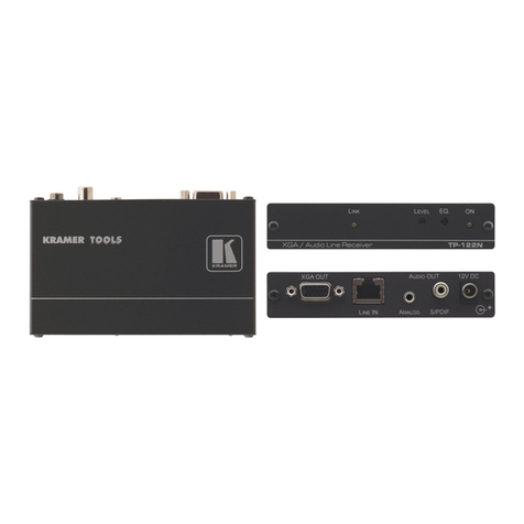
TP-141/TP-142 away from moisture, excessive sunlight and dust
Caution – No operator-serviceable parts inside unit.
Warning – Use only the Kramer Electronics input power
wall adapter that is provided with this unit
2
.
Warning – Disconnect power and unplug unit from wall
before installing or removing device or servicing unit.
1 Available from Kramer Electronics on our Web site at http://www.kramerelectronics.com
2 For example: model number AD2512C, part number 2535-000251


