Norbec E-CIRCUIT User manual

│ E-CIRCUIT – User Manual and Installation Guide
97, rue de Vaudreuil,
Boucherville (Quebec) J4B 1K7
Phone: (450) 449-1499 Fax: (450) 641-4657
Toll-free: 1 877 667-2321
** IMPORTANT **
PLEASE READ PRIOR TO
INSTALLATION AND START UP

│ E-CIRCUIT – Installation Guide and User Manual
2
Table of contents
Overview of the E-Circuit........................................................................................................................3
Installation Guide – E-Circuit Retrofit......................................................................................................4
Installation of an E-Circuit Electrical System on an Existing Norbec CL Door................................................4
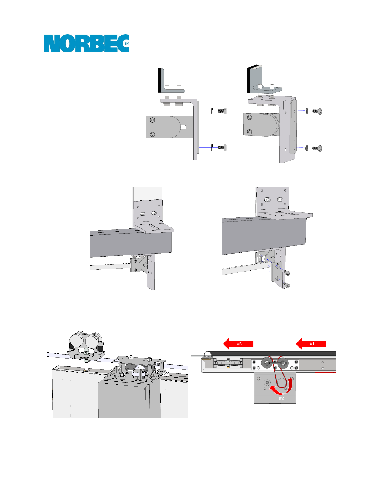
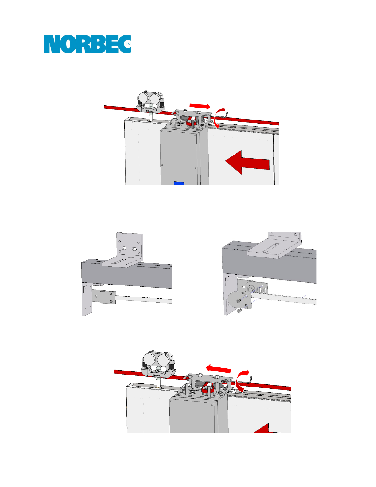
Installation Guide – Installation of the Electrical System Components .....................................................5
Installation of the Electrical System Components .........................................................................................5
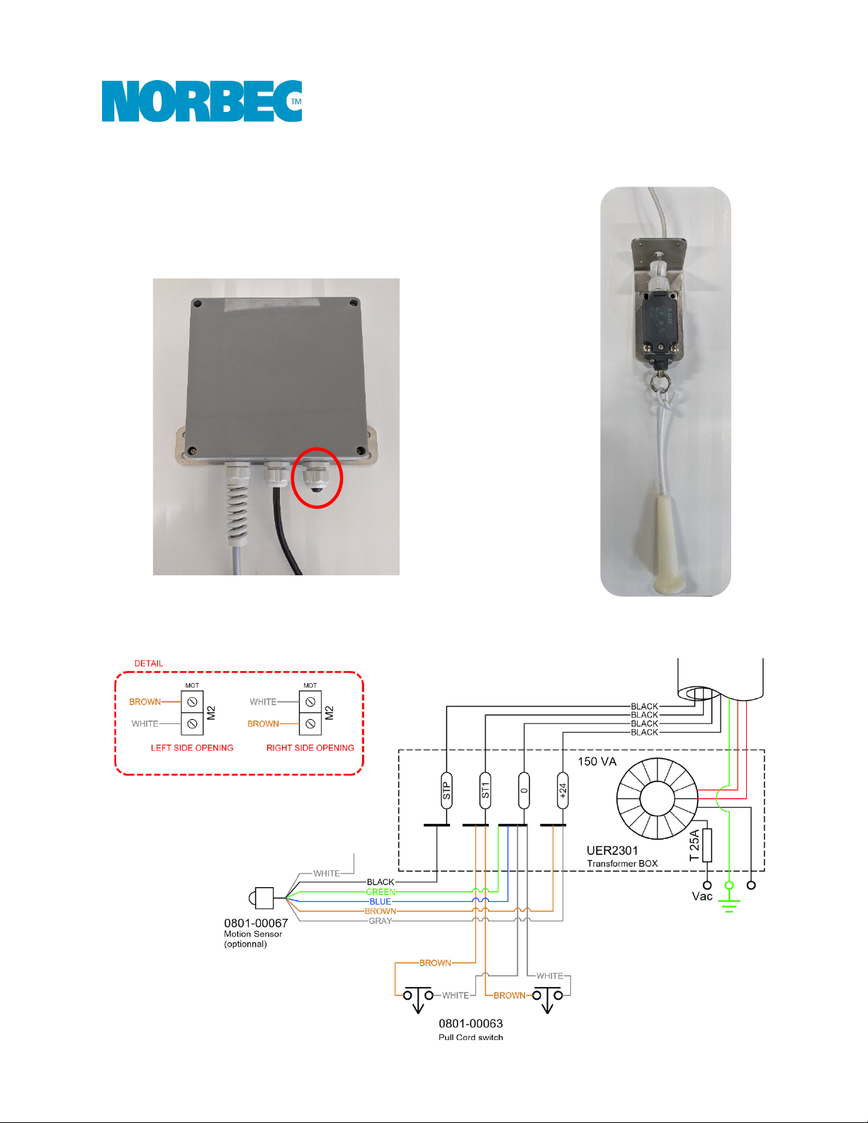
Installation Procedure – Pull Cord Switches (×2 Standard).......................................................................9
Installation Procedure – Anti-Pinch Safety Edge (Standard) ...................................................................10
Synchronization Procedure – Radio-Controlled (Optional).....................................................................13
Setup Steps ..................................................................................................................................................13
Installation Procedure – Photoelectric Safety Barrier (Optional)............................................................14
Installation Procedure – Contactless Opening Motion Sensor (Optional)................................................16
E-Circuit Wiring Diagram ......................................................................................................................18
User Manual ........................................................................................................................................19
Operating and Configuration Instructions ...................................................................................................19
Display..........................................................................................................................................................19
Electronic Obstacle Detection......................................................................................................................20
Description of Configuration Parameters ....................................................................................................20
Opening Mode..........................................................................................................................................20
Automatic Closure....................................................................................................................................20
Radar Function (Motion Sensor Option)...................................................................................................20
Partial Opening.........................................................................................................................................21
Flashing Light............................................................................................................................................21
Anti-Pinch Safety Edge (Standard)............................................................................................................21
Photoelectric Safety Barrier (Optional) ....................................................................................................21
Connection Procedure .................................................................................................................................21
Electrical Connections ..............................................................................................................................21
Configuration of Safety Options ...............................................................................................................22
Configuration of the Opening Direction ...................................................................................................22
Procedure for Changing Parameters ........................................................................................................22
Running the Learning Phase After a Power Failure ..................................................................................23
Table of Configuration Parameters..............................................................................................................23
Table of Alarms and Problems .....................................................................................................................24
Annex – Installation guide CL-1650 .......................................................................................................26

│ E-CIRCUIT – Installation Guide and User Manual
3
Overview of the E-Circuit
The E-Circuit is a system for automating the opening and closing of Norbec CL sliding doors.
The system consists of a transformer and a motor.
-120-Vac, 60 Hz power supply
-24-Vdc motor
Standard accessories:
-Anti-pinch safety edge
-Pull cord switches (×2)
Optional accessories:
-Radio-controlled push button
-Radio-controlled pull switch
-Contactless opening motion detector
-Photoelectric safety barrier

│ E-CIRCUIT – Installation Guide and User Manual
4
Installation Guide – E-Circuit Retrofit
Installation of an E-Circuit Electrical System on an Existing Norbec CL Door
1. Remove the end stops at each end,
as well as the cast-iron latch stop.
2. Remove the door from the rail to gain access to the top of the door.
3. Screw in the motor mounting block
on the top of the door
@ 14 in. from the edge opposite the
opening.
6 × #14 self-drilling metal screws × 1-
in. hex head
4. Add the pulley assembly
2 × M8×1.25, 16 mm bolt
2 × M8 lock washer
5. Assemble the motor housing
2 × M8×1.25, 12 mm bolt
2 × M8 flat washer

│ E-CIRCUIT – Installation Guide and User Manual
5
Installation Guide – Installation of the Electrical System Components
For the installation of the sliding door and frame, refer to the CL-1650 sliding door installation guide annexed
to this document.
Installation of the Electrical System Components
1. Install the end stop assemblies.
Latch stop – Left opening
Opening stop – Left opening
Latch stop – Right opening

│ E-CIRCUIT – Installation Guide and User Manual
6
Opening stop – Right opening
2. Attach the end of the belt to the small anchor on the door’s closing side.
3. Run the belt through the pulley assembly and around the gear.

│ E-CIRCUIT – Installation Guide and User Manual
7
4. Unscrew the movable pulley as much as possible with a 5 mm Allen key to move the pulley to the
right (5 mm ± 3/16 in.).
5. Attach the other end of the belt to the anchor on the door’s opening side.
Mark the length of the belt and cut off the excess.
To facilitate installation, push the door in the opening direction to maintain tension on the first
section of the belt.
6. On the pulley assembly, adjust the tension on the belt.
Tighten with a 5 mm Allen key to move the adjustable pulley to the left.

│ E-CIRCUIT – Installation Guide and User Manual
8
7. Hold the mobile pulley in position.
17 mm wrench or adjustable wrench.
8. Add the cover to the pulley assembly.

│ E-CIRCUIT – Installation Guide and User Manual
9
Installation Procedure – Pull Cord Switches (×2 Standard)
Pull cord switches come with a cable length of 240 in. [600 cm].
1. Position the switches in the desired locations.
2. Run the cables along to the transformer box.
3. Run the cables through the sealed grommet under the transformer.
4. Connection in the transformer according to the following connection diagram:
*See p. 18 for the complete E-Circuit Wiring Diagram

│ E-CIRCUIT – Installation Guide and User Manual
10
Installation Procedure – Anti-Pinch Safety Edge (Standard)
The anti-pinch safety edge installed on the door serves as a mechanical safety edge.
1. Attach plate A2 to the door jamb according to these dimensions:
HT = 1,500 mm [59 in.]
H1 = 5 mm [3/16 in.]
H2 = 710 mm [27 15/16 in.]
H3 = 1,416 mm [55 3⁄4 in.]
*See p. 12 for the complete Installation Diagram – Anti-Pinch
Safety Edge
2.
Insert the safety edge onto plate A2 and secure it using holes A1
and A3.
3. Run the cabling along the edge and top of the door toward the
motor housing.
* Be careful not to expose the top corner of the door opposite the
point of contact with the end stop.

│ E-CIRCUIT – Installation Guide and User Manual
11
4. Run the cable through the sealed grommet on the top of the motor.
5. Connect the cables according to the following diagram.
Terminal M5
*See p.18 for the complete E-Circuit Wiring Diagram
6. Select the switch and commutator near terminal M5 of the motor housing.
Option
Switch
Commutator
Diagram
Safety nose
FT1 = OFF
#1: NPN

│ E-CIRCUIT – Installation Guide and User Manual
12
Figure 1: Installation Diagram – Anti-Pinch Safety Edge

│ E-CIRCUIT – Installation Guide and User Manual
13
Synchronization Procedure – Radio-Controlled (Optional)
START command option:
Radio-controlled button ↓
Radio-Controlled pull switch ↓
Setup Steps
1. Power up the system.
2. Open the motor housing cover.
3. Press button P1 on the internal radio receiver once.
4. The LED light will turn on.
5. Activate the START command on the remote control.
a. Button: Press for 2 seconds.
b. Pull switch: Pull for 2 seconds.
6. When the control is released, the LED light turns off, indicating that the remote control has been
memorized.
If the remote control is not recognized, the LED light stays on for 10 seconds.
7. Repeat the steps for each remote control.
Internal radio receiver

│ E-CIRCUIT – Installation Guide and User Manual
14
Installation Procedure – Photoelectric Safety Barrier (Optional)
1. Screw the bracket and the sensor onto the door underneath the safety nose.
2. Run the cabling along the edge and top of the door toward the motor housing.
Be careful not to expose the top corner of the door opposite the point of contact with the end stop.
3. Attach the reflector mirror so that it is in the sensor’s field.
4. Run the cable through the sealed grommet on the top of the motor.

│ E-CIRCUIT – Installation Guide and User Manual
15
5. Connect the cables according to the following diagram.
Terminal M5
*See p. 18 for the complete E-Circuit Wiring Diagram
6. Select the switch and commutator near terminal M5 of the motor housing.
Option
Switch
Commutator
Diagram
Photoelectric barrier
(optional)
FT2 = OFF
#2: PNP

│ E-CIRCUIT – Installation Guide and User Manual
16
Installation Procedure – Contactless Opening Motion Sensor (Optional)
The motion sensor comes with a cable length of 192 in. [500 cm].
1. Position the switches in the desired locations.
2. Run the cables along to the transformer box.
3. Run the cables through the sealed grommet under the
transformer.
4. Connect to the transformer according to the following connection diagram:
*See p. 18 for the complete E-Circuit Wiring Diagram

│ E-CIRCUIT – Installation Guide and User Manual
17
5. Follow the procedure for changing parameters and change parameter RA = 1.
6. Calibrate the operating distance.
7. Operates as follows.

│ E-CIRCUIT – Installation Guide and User Manual
18
E-Circuit Wiring Diagram

│ E-CIRCUIT – Installation Guide and User Manual
19
User Manual
Operating and Configuration Instructions
← Keypad
1. Partial
2. Menu
3. Open
Housing →
Pull switch – Start
Display
During normal operation, the screen displays the following information:
Display
Description
OP
Door opening
CL
Door closing
ST
Door locked for latching
F
Photocells triggered
S
Stop button pressed
E1
First start or power restored after failure; press START to start the learning phase
E3
Accidental position loss or function change; press START to calibrate
E4
Double safety activation: remove the obstacle and press START to calibrate
When the door is closed, the screen shows the number of times the door has been opened (thousands).
When the door is open and closing is activated, the screen displays the countdown of the remaining seconds
before closing. [Adjustable, see Description of Configuration Parameters].

│ E-CIRCUIT – Installation Guide and User Manual
20
Electronic Obstacle Detection
Electronic obstacle detection is active when opening and closing.
When it is operating, it reverses the door’s movement without
disabling
automatic closure. If detection occurs twice consecutively,
the door’s movement is reversed by 4
in. [10 cm] and goes to the
STOP position. Once the door’s path has been cleared, press START
and the door opens fully at reduced speed. Press START again to
r
eactivate normal opening and closing.
Description of Configuration Parameters
Opening Mode
When parameter ST =0: Opening/Closure mode
After the START command:
Status
Action
The door is closed
The door opens.
The door is opening
The door stops and closes again.
The door is open
The door closes again.
The door is closing
The door stops and opens again.
When parameter ST =1: Opening/Stop/Closure mode
After the START command:
Status
Action
The door is closed
The door opens.
The door is opening
The door stops and stays open; press START to close
the door again.
The door is open
The door closes again.
The door is closing
The door stops and stays open; press START to open
the door again.
If the automatic closure parameter is set to: AU = 1, after the START command, the pause time is restored
before closing.
If the radar function parameter is set to RA = 1, when the door is opening, the START command is ignored.
Automatic Closure
When parameter AU = 1, after the START command, the door will open and stay open for a time period
defined by the pause time parameter, before closing again.
Radar Function (Motion Sensor Option)
When parameter RA = 1, when the sensor detects movement, the door will open and stay open for a time
period defined by the pause time parameter, before closing again.
Table of contents
Popular Door Opening System manuals by other brands

EZ-ACCESS
EZ-ACCESS CONCIERGE Series installation manual

Securitron
Securitron MXD-62 Installation and operating instructions

TOPP
TOPP HS2 Instructions for use

Dormakaba
Dormakaba 8600 IS installation instructions

Becker
Becker A100/25 5E Assembly and operating instructions

Dormakaba
Dormakaba RTS Series installation instructions