ASTEC b.1000 User manual

astec gmbh. design beschlaege. mauersteige 2. d-72469 messstetten-tieringen. fon +49 7436-92979-0
gf simone koch-schlegel. HRB 400802 stuttgart. www.astec-design.de. info@astec-design.de
assembly instructions
floor guided roller fitting
astec b.1000
1/8 –10.2021
1.
ensure that the supplied parts are complete by checking the packing list.
the floor installation set is supplied preassembled.
2.
make sure that tools and work materials are to hand:
■
drill
■
torx screwdriver T20
■
open-ended spanner sw 8
■
hex key size 2.5 + 3
■
hexagon socket size 4
■
filler, e.g. cement, PU adhesive
■
underlay material
■
silicone
essential: groove must be cut into the floor (approx. 37 x 67 mm)

astec gmbh. design beschlaege. mauersteige 2. d-72469 messstetten-tieringen. fon +49 7436-92979-0
gf simone koch-schlegel. HRB 400802 stuttgart. www.astec-design.de. info@astec-design.de
assembly instructions
floor guided roller fitting
astec b.1000
2/8 –10.2021
3.
affix door guide rail (1) to glass panel (2)
■
clean glass edge (must be free of dust and grease)
■
check straightness of glass
important: the straightness of the door guide rail must not be affected by a
possible deflection of the glass.
■
pull off the protective foil over the layer of adhesive on the door guide rail.
■
adhere the entire surface of the door guide rail to the full length of the glass edge.
important: subsequent removal of the door guide rail is very difficult!
■
fill the gap between glass and door guide rail with silicone
4.
install floor track
■
if necessary, connect multi-part floor track (3) using connector (4) with countersunk
screw M5x20.
■
position vertically in the groove
■
drill holes and insert dowels
■
align track using cylinder head screw M5x16 (5). it must be ensured that the horizon-
tal fitting, levelness and straightness of the floor track are guaranteed. the floor track
is to be underlaid in the cylinder head screw areas.
important: track must be levelled most accurately!
(1) door guide rail
(2)
(1)
(4)
(5)

astec gmbh. design beschlaege. mauersteige 2. d-72469 messstetten-tieringen. fon +49 7436-92979-0
gf simone koch-schlegel. HRB 400802 stuttgart. www.astec-design.de. info@astec-design.de
assembly instructions
floor guided roller fitting
astec b.1000
3/8 –10.2021
■
secure track to floor using half-round screw 5 x 50 TX20 (6)
5.
fill space in the groove with filler (7), e.g. cement or PU adhesive
6.
install floor covering (8)
7.
assemble roller bearing rail (9)
■
install rail
■
secure rail with hexagon spacer (10)
(6)
(3) floor track
(5)
(6)
(7)
(8)
(9) roller bearing rail
(9)
(10)

astec gmbh. design beschlaege. mauersteige 2. d-72469 messstetten-tieringen. fon +49 7436-92979-0
gf simone koch-schlegel. HRB 400802 stuttgart. www.astec-design.de. info@astec-design.de
assembly instructions
floor guided roller fitting
astec b.1000
4/8 –10.2021
8.
install ceiling track
8.1
ceiling track 40/20mm (14)
■
position and align vertically above the floor installation set
■
insert end stops in the ceiling track
■
adjusting the door leaf
8.2
ceiling track 60/30mm with damping system(15)
■
disassemble the two-part ceiling track and detach the countersunk screws m5x8mm
and the cover plate from the support rail using the size 3 hex key. the pre-installed
door damper/endstop may remain in place.
■
align the ceiling track vertically above the floor track and mark its position. mark the
mounting holes of the support rail, drill the necessary holes, carefully hammer the
anchors into place and screw down the support rail.
(14)
(15)

astec gmbh. design beschlaege. mauersteige 2. d-72469 messstetten-tieringen. fon +49 7436-92979-0
gf simone koch-schlegel. HRB 400802 stuttgart. www.astec-design.de. info@astec-design.de
assembly instructions
floor guided roller fitting
astec b.1000
5/8 –10.2021
trigger assembly on the door leaf
■
attaching the end stop/damping triggers
please refer to the order drawings for the correct positioning of the end stop or damping
triggers. the glass surfaces and glass edges must be cleaned using the provided cleaning
cloth. make sure the surfaces and edges are free of dust and grease. for a solid adhesion,
the provided primer must be applied to the bond areas on the glass door leaf. the recom-
mended application temperature for the primer is between 15° C and 25° C. push on the
marked area on the cartridge until you feel and hear a click. apply evenly on the bonding
areas on the glass. depending on temperature, humidity, air circulation and porosity of the
surface, allow a flash-off time of at least 5 minutes. attention: only apply one coat of primer!
■
completely remove the large protective sheet from the tape and attach the tape to the under-
side of the trigger. completely remove the second protective sheet and press the trigger onto
the marked area on the door leaf with approx. 20 N/cm2. the final bond strength is reached
after about 72 hours at 20° C or faster at higher temperatures.
■
safety warning: only use in well-ventilated spaces, do not breathe in, use provided gloves for
protection, avoid contact with eyes and skin.
the beveled edge of the trigger
always points toward the outer edge
of the glass, i. e. in the direction of
the damping/end stop
adjusting the door leaf
for surface mount, adjust the door leaf, set the final end stop or damping positions according
to the affixed trigger and fasten them using the set screws. test the damping and stop func-
tions. attach the cover plate and fasten.
for flush mount, do not remove the cover plate before screwing down the ceiling track.
please note: the height adjustment for the trigger cannot be reached without first unhinging
the door leaf.

astec gmbh. design beschlaege. mauersteige 2. d-72469 messstetten-tieringen. fon +49 7436-92979-0
gf simone koch-schlegel. HRB 400802 stuttgart. www.astec-design.de. info@astec-design.de
assembly instructions
floor guided roller fitting
astec b.1000
6/8 –10.2021
9.
check running performance and if necessary, carry out fine adjustment
■
the height of each roller can be adjusted (11)
■
adjust using screwdriver
10.
assemble cover strip (12)
■
install strip (cut into at least two sections)
■
secure the strips with countersunk spacer screws M5x10 (13) in the hexagon spacers
11.
if applicable, mount pull handles/flush pulls and clean the fittings and handles with soft cloth
(11)
(13)
(12)
(12) cover strip

astec gmbh. design beschlaege. mauersteige 2. d-72469 messstetten-tieringen. fon +49 7436-92979-0
gf simone koch-schlegel. HRB 400802 stuttgart. www.astec-design.de. info@astec-design.de
7/8 –10.2021
assembly instructions
example of assembly
astec b.1000 with ceiling track 60/30mm and damping system
damping system trigger
support rail
two-part aluminum
u-profile, ceiling track
60/30mm
cover plate
b.1000 floor track
door damper, right
door damper
end fastener
damping system trigger:
the beveled edge of the trigger
always points toward the outer edge
of the glass, i. e. in the direction of
the door damper/end stop.
felt strip

astec gmbh. design beschlaege. mauersteige 2. d-72469 messstetten-tieringen. fon +49 7436-92979-0
gf simone koch-schlegel. HRB 400802 stuttgart. www.astec-design.de. info@astec-design.de
8/8 –10.2021
care and maintenance recommendations
for floor guided roller fitting astec b.1000
the separate profiles of the b.1000 are made of aluminium. all the profiles are anodized after precision
cutting and accurate machining.
although anodized aluminium does not corrode under normal atmospheric conditions, regular care is
essential to maintain a good, decorative surface as well as to ensure its hygienic properties.
use a commercially available household cleaning agent for regular care and clean the surfaces with a
soft cloth. as a general rule, only wipe over with a damp cloth, do not wet-clean. it is imperative to avoid
harsh, abrasive cleaning agents and cleaning tools.
the bearings of the rollers are always sealed and lubricated for life. wipe the rollers with a damp cloth
at regular intervals. the collection of dust and other air contaminants can form a film. uneven running
and possible jamming of the rollers is the result. the floor track should be regularly cleaned with a
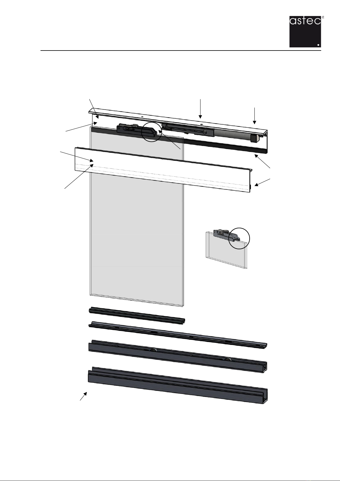
vacuum cleaner in order to remove coarse dirt in particular. the cover strips are in two sections and can
be removed with little effort if required. small stones and coarse dirt on the surface of the floor track
should be removed immediately as these can get stuck between the door guide profile and the cover
strip. this can lead to annoying scratching noises, surface damage and possible jamming of the doors.
please always use tools that are in good condition to avoid damage to the inner surfaces of the screws.
these are namely also a decorative element of the fitting.
Table of contents
Popular Door Opening System manuals by other brands

Assa Abloy
Assa Abloy effeff ePED 1386Z1LB7 04S0 Series Brief instructions

Sesamo
Sesamo PROSWING operating instructions

GTO/PRO
GTO/PRO EXIT WAND installation manual

Falcon
Falcon Ferme-Porte SC60 series installation instructions

Detex
Detex AO19 Quick install guide

Woelm
Woelm HELM GT-L 50 installation instructions

Hailo
Hailo HFO Instructions for assembly and use

Assa Abloy
Assa Abloy Norton UniTrol UNI-1600BC Series installation instructions

Elvox
Elvox Sound system GIOTTO operating instructions

Tucker
Tucker SW10 installation guide

Henderson
Henderson HUSKY Folding 25 Series Fitting instructions

Assa Abloy
Assa Abloy Corbin Russwin PED5200 installation instructions