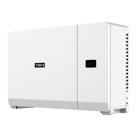
TBEA TC500K3US-O User manual


I
Contents
1 About this Manual.........................................................................................4
1.1 Preface..................................................................................................4
1.2 Introduction..........................................................................................4
1.3 Applicable Scope..................................................................................5
1.4 Manual Instruction...............................................................................6
2 Safety Precautions.........................................................................................7
2.1 Safety Precautions................................................................................7
2.2 Notes on Operation............................................................................ 11
2.2.1 Live Line Measurement .......................................................... 11
2.2.2 Opening the Plant.................................................................... 11
2.2.3 Requirements Prior to Connecting the Switches on AC and DC
Sides.................................................................................................12
2.2.4 Notes on Shutdown.................................................................13
3 Product Delivery .........................................................................................14
3.1 Scope of Delivery...............................................................................14
3.2 Nameplate of TC500K3US-O............................................................15
3.3 Storage ...............................................................................................16
3.4 Transportation....................................................................................18

II
4 Product Description....................................................................................19
4.1 Grid-connected System......................................................................19
4.2 Appearance.........................................................................................21
4.3 Appearance Description..................................................................... 22
4.3.1 Dimensions..............................................................................22
4.3.2 Ventilation Design...................................................................23
4.4 Circuit Introduction............................................................................23
4.5 Terminals............................................................................................25
5 Product Installation ....................................................................................27
5.1 Basic Installation Pequirements.........................................................27
5.2 Installation Environment....................................................................28
5.2.1 Ground Requirements .............................................................28
5.2.2 Requirements of the Minimum Space for Outdoor Uses........29
5.2.3 Requirements of the Minimum Space for Indoor Uses...........32
5.3 Requirements of the Alignment of Wires, Ventilation and Others.....33
5.3.1 Requirements of Cable Trenches ............................................33
5.3.2 Ventilation Requirements........................................................34
5.3.3 Other Requirements ................................................................36
5.4 Wiring Specifications.........................................................................37
5.5 Fixation and Protection of Connection Cables...................................38
5.5.1 Fixation of Cables...................................................................38

III
5.5.2 Cable Protection......................................................................39
5.6 Installation Process ............................................................................39
6 Installation Preparations............................................................................42
6.1 Pre-Installation Inspection .................................................................42
6.2 Installation Tools and Parts................................................................42
7 Equipment Installation...............................................................................43
7.1 Equipment Transportation..................................................................43
7.1.1 Precautions..............................................................................43
7.1.2 Packaging and Logos ..............................................................44
7.1.3 Transportation Packaged.........................................................46
7.1.4 Transportation without Packaging...........................................47
7.2 Field Installation ................................................................................49
8 Electrical Connection..................................................................................54
8.1 Precautions.........................................................................................54
8.2 Input and Output Requirements .........................................................55
8.3 Cable Requirements...........................................................................56
8.4 Wiring Components ...........................................................................58
8.5 Preparations for Electrical Wiring......................................................62
8.6 DC Side Wiring..................................................................................63
8.7 AC Side Wiring..................................................................................69
8.8 Ground Connection............................................................................73

IV
8.9 Communication Wiring......................................................................75
8.10 Power Supply...................................................................................76
8.10.1 Self-Powered Mode...............................................................76
8.10.2 External Power Supply Modes..............................................77
8.11 Seal at the Bottom of Cabinet ..........................................................78
9 Installation Inspections...............................................................................82
10 Commissioning..........................................................................................84
10.1 Commissioning Requirements .........................................................84
10.2 Check before Commissioning..........................................................85
10.2.1 Check the PVArray ..............................................................85
10.2.2 Check the Inverter.................................................................85
10.2.3 Check the Parameters of the Inverter Grid............................85
10.3 Preparing before Power on...............................................................87
10.4 Power on ..........................................................................................88
10.5 Completion of the Test Run .............................................................88
11 Appendixes.................................................................................................89
11.1 Technical Data..................................................................................89
11.1.1 Electrical Part........................................................................89
11.1.2 Mechanical Part.....................................................................91
11.1.3 System Data ..........................................................................91
11.1.4 Transformer Parameters ........................................................91

V
11.2 Warranty Statement..........................................................................92
11.2.1 Normal Warranty...................................................................92
11.2.2 Extended Warranty................................................................94
11.2.3 Contact Us.............................................................................94

TC500K3US-O Installation Instructions
1
Important Safety Instructions
Save These Instructions
This manual contains important instructions for the following product:
TC500K3US-O
The product is designed and tested in accordance with international safety
requirements, but as with all electrical and electronic equipment, certain
precautions must be observed when installing and/or operating the product. To
reduce the risk of personal injury and to ensure the safe installation and
operation of the product, you must carefully read and follow all instructions,
cautions and warnings in this manual.
Warnings in this Document
“DANGER” indicates a high degree of potential hazards, if not
avoided, which will lead to death or serious injury.
“WARNING” indicates a moderate degree of potential hazards, if not
avoided, which may result in death or serious injury.

TC500K3US-O Installation Instructions
2
“CAUTION” indicates a low level of risks, if not avoided, which may
result in moderate or minor injuries to personnel.
“NOTICE” indicates potential hazards, if not avoided, which may
cause the result that the equipment cannot work properly or cause losses to
property.
“DISCRIPTION” is the additional information of the manual, the
emphasis and supplement of the contents, which may also provide product
optimization tips or skills that can help you solve certain problems or save
your time.
Warnings on this product
Please note the identification labels on the engine body, including the
following:
Warning electric shock
This symbol indicates that the inverter interior contains high voltage,
and an electric shock may be caused when touching.

TC500K3US-O Installation Instructions
3
Warning hot surface
This symbol indicates that the temperature here is higher than that
within the body acceptable range, so please do not touch arbitrarily to avoid
personal injuries.
PE
This symbol indicates that it is the PE port, and solid grounding is
needed to ensure the safety of the operating personnel.
ON
This symbol is the “ON” position schematic diagram of AC and DC
circuit breakers.
OFF
This symbol is the “OFF” position schematic diagram of AC and DC
circuit breakers.

TC500K3US-O Installation Instructions
4
1 About this Manual
This chapter introduces the main contents, facing readers, notice for use
and explanations to symbols to help users have a better understanding and
using of this manual.
1.1 Preface
Dear customers, appreciating for using TC500K3US-O PV grid-connected
inverters developed by TBEA. We sincerely hope this product will meet your
needs and expect you to put forward more views on the performance and the
function of this product. We continue to improve the quality of this product.
1.2 Introduction
This manual applies to TC500K3US-O PV inverter (hereinafter referred
to as ‘inverter’),this manual contains the followings contents.
Safety instructions
This manual introduces safety signs during operation and precautions of
dangers, warnings and cautions during installation.
System Introduction
This manual introduces the scope of delivery of inverters, identification
methods, storage and structure, electrical modality principle of inverters.

TC500K3US-O Installation Instructions
5
Installation design
This manual introduces the system design, installation environment, and
electrical wiring design as well as installation process of inverter.
Installation and inspection
This manual introduces mechanical installation, electrical installation, and
communication connections of the inverter, and the inspection methods after
installation.
Commissioning guidance
This manual introduces precautions of the inverter during test
commissioning and the operational process of the inverters.
Others
This manual introduces the technical data of the inverter, warranty clauses
and the contact information of our company.
1.3Applicable Scope
This manual is for the staff working on installing and operating of the
inverter. Staff for installation and maintenance shall be equipped with certain
expertise in electrical, wiring and mechanical fields, familiar with electrical,
mechanical schematics and features of electronic components. It is also
required for the staff to be familiar with the content of the document and to
comply with the safety regulations.

TC500K3US-O Installation Instructions
6
1.4 Manual Instruction
Please read this manual carefully before installing the product. Please
keep this manual on hand for quick reference. In addition to this installation
manual, the following documents can also be used:
TC500K3US-O Operation Manual
The images, logos, symbols, etc. used in this manual are owned by TBEA
Xi'an Electrical Technology Co., Ltd.. No part of this document can be
reproduced by unauthorized persons without the prior written permission of
our company.
Manual content will be constantly updated and corrected, but it is
inevitable that there are slight discrepancies from material objects or errors in
this manual. Users will be subject to the purchased actual products and can
download latest version of the manual at http://www.tbeapower.com or from
other sales channels.

TC500K3US-O Installation Instructions
7
2 Safety Precautions
This chapter introduces the overview of safe use of TC500K3US-O PV
inverters and safety precautions needed to be followed during installation and
operation.
2.1 Safety Precautions
Danger to life from electric shock due to live voltage.
High voltages are present in the live components of the inverter. Touching
live components results in death or serious injury due to electric shock.
When working in a high contact-risk environment, wear personal
protective equipment.
Do not touch live components.
Follow the instructions precisely.
Observe all the safety messages on the product and in the documentation.
Before any work on the inverter is performed, always disconnect all
external voltage sources of the plant.
(1) Grid voltage
(2) External power supply
(3) DC voltage of PV array

TC500K3US-O Installation Instructions
8
Ensure that no disconnected components can be reconnected.
After disconnecting the inverter from the voltage sources, wait at least 5
minutes for the capacitors of the inverter to discharge completely.
DC cables connected to PV modules that are exposed to sunlight are live.
Touching live components results in death or serious injury.
Wear suitable personal protective equipment for all work on the
inverter.
Prior to connecting the DC cables, ensure that the DC cables are
voltage-free.
Unauthorized modification or damaged device can lead to danger to
life due to electric shock or fire hazard.
It is forbidden to refit the equipment and no unauthorized person can use
the equipment.
Initially and visually check whether the equipment is damaged or has
other dangerous conditions before operating.
Check whether other external equipments or circuit connections are in
safe states.
Confirm that this equipment is in a safe state, and then operate.

TC500K3US-O Installation Instructions
9
Danger to life when the inverter is not locked
If the inverter is not locked, this means that unauthorized persons have
access to components carrying lethal voltage. Touching live components can
result in death or serious personal injury due to electric shock.
Always keep the inverter locked.
Remove the keys from the door locks and from the key switch.
Keep the keys in a safe place.
Ensure that unauthorized persons do not have access to the PV plant.
Danger to life due to blocked escape routes
In hazardous situations, blocked escape routes can lead to death or serious
injury. It is imperative that the escape route is freely accessible at all times.
An escape route of at least 3 ft. (915 mm) width must be available at all
times. Make sure the minimum passage width of the route meets local
standards.
Remove all tripping hazards from the escape routes.
Do not place any objects in the escape route area.
If two inverters have been installed facing each other, never open the
doors of the both inverters simultaneously.

TC500K3US-O Installation Instructions
10
Only professional electricians or persons are allowed to work on the
product.
It must ensure that at least 2 personnel are working in the field until the
equipment is safely de-energized and discharged completely during
maintenance.
Only after getting permission of local power company and completing
installation by qualified persons, can the inverter be connected with the grid.
Electrical installation must comply with local electrical installation
standards.
Improper contacts or operations of printed circuit boards or other
static-sensitive components will cause damages to the device.
Avoid unnecessary contacts with the circuit board.
Comply with the electrostatic protection specification, wear antistatic
wrist straps.
During the overhaul of the plant and routine maintenance, turn the
breakers on AC and DC sides to “OFF” position to avoid irrelevant personnel
from approaching or meeting with accident. It is recommended to erect
warning labels or set up barrier tape.
This manual cannot cover all possible cases in transportation, installation,

TC500K3US-O Installation Instructions
11
commissioning. If encountering some cases not described in the manual, please
contact TBEA Co.,Ltd..
2.2 Notes on Operation
2.2.1 Live Line Measurement
High voltage is present in the plant. Touching by accident may result in
death or personal injury due to electric shock. Prior to live line measurement, it
is imperative to wear suitable personal protective equipment and instruments
(such as wearing insulated gloves, etc.).
2.2.2 Opening the Plant
Even if all connections to the inverter have been disconnected, lethal
voltage may still be present in the capacitor of the inverter. After disconnecting
the inverter from voltage sources, wait at least 5 minutes for the capacitor of
the inverter to discharge completely before maintenance and overhaul or other
operation.

TC500K3US-O Installation Instructions
12
2.2.3 Requirements Prior to Connecting the Switches on AC and
DC Sides
Breakers on AC, DC sides shall be disconnected and the protective panel
against accidental touch shall be installed or protective measures be taken.
All connections must be carried out in accordance with the installation
manual and schematics.
Protective earthing connection has been done with power grid
transmission and internal power supply.
Confirm that the inverter has been closed and locked.
Emergency stop switch is in loose status.
It shall be confirmed that the rated voltage, frequency and phase sequence
of the connection terminals on AC side are in line with requirements.
It shall be confirmed that the voltage polarity on DC side is correctly
connected.
Check PV array by insulation test to ensure no ground fault.

TC500K3US-O Installation Instructions
13
2.2.4 Notes on Shutdown
There are two cases for shutdown, in normal maintenance and in fault
occurring. The procedures for respective shutdown are as follows:
Normal maintenance and overhaul
Shutdown procedure:
(1) Turn the key switch to “OFF”.
(2) Observe the LCD display until the rate of work of the display is
shown as “0”.
(3) Turn both AC and DC circuit breakers to “OFF”.
(4) Disconnect the front and rear breakers of the inverter.
When fault or emergency occurring
Shutdown procedure:
(1) Press down the emergency stop button then turn the key switch to
“OFF”.
(2) Turn both AC and DC circuit breakers to “OFF”, and then
disconnect the preamplifier breaker and after stage amplifier circuit
breaker.
(3) Turn the key switch to “OFF”.

TC500K3US-O Installation Instructions
14
3 Product Delivery
This chapter describes the scope of delivery of TC500K3US-O, the name
plate recognition and storage methods of inverter.
3.1 Scope of Delivery
TC500K3US-O is delivered with wooden case packaging. During
transportation, transportation requirements described in the manual must be
followed. If there is any doubt, contact the TBEA Company.
The packing case of TC500K3US-O contains the following items:
Table 3-1 Supply scope of TC500K3US-O
Items
Name
Quantity
Remarks
1
TC500K3US-O PV
Grid-Connected Inverters
1
Including cabinet keys
and accessories
2
TC500K3US-O Installation Manual
1
3
TC500K3US-O Operation Manual
1
4
Warranty Card
1
5
Certificate
1
6
Test Report
1
TC500K3US-O has been rigorously tested and inspected in the
factory before transportation, but collisions, dumping and other
unforeseen circumstances may still occur during transportation. Therefore,
Table of contents
Other TBEA Inverter manuals
Popular Inverter manuals by other brands

Fuji Electric
Fuji Electric FRENIC-Lift series instruction manual
MCW
MCW HIB0150EN200V user guide

Well
Well UPS-HEATST-COMMANDER300W-WL Operation manual

Bosch
Bosch mm-Si plus EU1510 Series Planning and installation instructions
PROLiNK
PROLiNK IPS1200A quick guide
Omron
Omron SYSDRIVE 3G3EV-AB CUE Series installation manual
