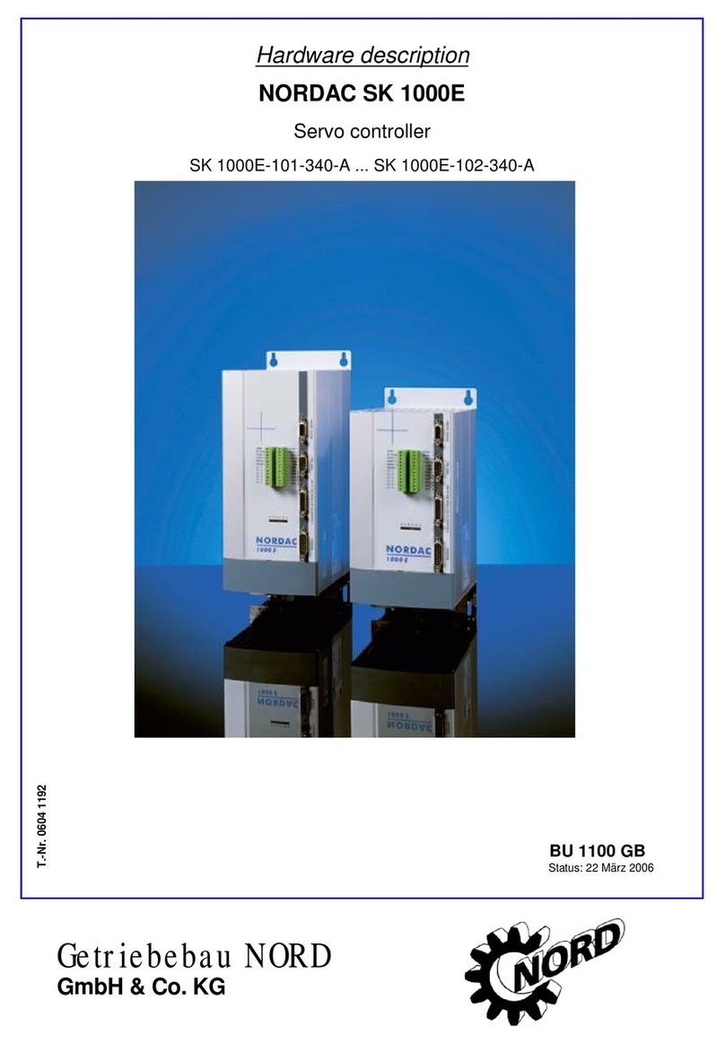
nord NORDAC SK 1 E Series User manual

Manual
NORDAC SK 1xxE Series
SK 140E ÆElectronic motor starter
SK 150E ÆElectronic soft starter
SK 160E ÆElectronic reversing starter
BU 0100 GB
GetriebebauNORD
GmbH & Co. KG

Table of content
2 BU 0100 GB
1 General description............................................................................................................................ 3
1.1 Delivery.........................................................................................................................................................4
1.2 European EMV (EMC) guideline....................................................................................................................4
2 Electronic Motor Starter SK 140E................................................................................................... 5
2.1 Principle of function......................................................................................................................................5
2.2 Device design................................................................................................................................................6
2.2.1 SK 140E-1-O
......................................................................................................................................6
2.2.2 SK 140E-1-BSG2
................................................................................................................................6
2.3 Electrical connection.....................................................................................................................................7
2.4 Display and settings......................................................................................................................................8
2.4.1 Status LEDs
.......................................................................................................................................8
2.4.2 Slide switch for automatic operation
.................................................................................................8
3 Electronic Soft Starter SK 150E....................................................................................................... 9
3.1 Principle of function......................................................................................................................................9
3.2 Device design..............................................................................................................................................10
3.2.1 SK 150E-1-O-3D-T125
.....................................................................................................................10
3.2.2 SK 150E-1-BSG2-3D-T125
...............................................................................................................10
3.3 Electrical connection...................................................................................................................................11
3.4 Display and settings....................................................................................................................................12
3.4.1 Status LEDs
.....................................................................................................................................12
3.4.2 Setting the potentiometers and dip switches
..................................................................................13
3.4.3 Slide switch for automatic operation
...............................................................................................17
4 Electronic Reversing Starter SK 160E.......................................................................................... 18
4.1 Principle of function....................................................................................................................................18
4.2 Device design..............................................................................................................................................19
4.2.1 SK 160E-1-O(-C)-3D-T125
...............................................................................................................20
4.2.2 SK 160E-1-BSG2(-C)-3D-T125
.........................................................................................................20
4.2.3 SK 160E-1-x(-C)-MS
........................................................................................................................20
4.2.4 SK 160E-AS1-x(-C)-MS
....................................................................................................................20
4.3 Electrical connection...................................................................................................................................21
4.4 Display and settings....................................................................................................................................22
4.4.1 Status LEDs
.....................................................................................................................................22
4.4.2 Rotary dip code switches for locking time
.......................................................................................23
4.4.3 Slide switch for automatic operation
...............................................................................................23
5 Options / Accessories SK 1xxE...................................................................................................... 24
5.1 SK 1xxE on motor with electromechanical brake .......................................................................................24
5.1.1 SK 1xxE with integrated brake rectifier
...........................................................................................24
5.1.2 SK 1xxE with separately installed brake rectifier
.............................................................................24
5.2 Wall-mounting kit .......................................................................................................................................25
5.3 System plug for power input or motor output............................................................................................26
5.4 Signal plug M12 for control signals..............................................................................................................27
5.5 AS interface bus connection.......................................................................................................................28
5.5.1 AS interface as additional assembly
................................................................................................29
5.5.2 AS interface as additional optional assembly
..................................................................................29
6 Technical data / Dimensions ......................................................................................................... 30
7 Maintenance and service notes..................................................................................................... 32
8 Index................................................................................................................................................... 33
9 Agencies and branch offices.......................................................................................................... 34

NORDAC SK 1xxE
BU 0100 GB Technical Modifications Reserved 3
1 General description
The product series NORDAC SK 1xxE constitutes a motor or wall-mounted electronic component that can be
used to handle simple drive or switching functions. The following types are part of this product series:
SK 140E Electronic motor starter
(Startup in one direction)
SK 150E Electronic soft starter
(Soft startup and run-down with adjustment of time and torque)
SK 160E Electronic reversing starter
(Startup possible in both directions)
The electronics of this motor starter series are integrated into the motor's terminal box. They can be directly
mounted on top of the motor (motor-integrated) or on the wall (proximity of motor). Each starter possesses an
assessment of a thermal protector (temperature probe or control) and an optional brake rectifier. A red or a
green LED visable from the outside through a transparent screw plug, indicating the devices status.
The NORDAC SK 140E enables a switching operation of a three-phase asynchronous motor in one direction.
This allows for cost-efficient switching directly at the drive.
The NORDAC SK 150E enables a soft start-up and run-down of three-phase asynchronous motors. This
allows for starting and stopping of the drive smoothly. With the soft starter, both torque and times can be set
separately for the startup and rundown of a drive.
The NORDAC SK 160E enables the switching operation of a three-phase asynchronous motor in both
directions. 2 rotary dip code switches are used to set a locking time to protect the installation against damage
caused by too quick a reversal.
The entire power range of the motor starter series is covered by one component size. The power range of the SK
140E reaches from 0.12 kW to 3.0 kW, that of the SK 150E and SK 160E cover a range from 0.12 to 4.0 kW.
Motor sizes 80 to 112 (with the SK 140E up to size 100) allow for direct mounting; sizes 63 to 71 require a simple
adapter plate (Mat. No. 11015410).
The number of poles of a motor is immaterial; the only determining variable for the motor starter are the power
consumption and the motor size.
The control electronics require 24 VDC (15 ...30 VDC, ≈50 mA) supply voltage, e.g., from a PLC or another power
supply.
Optionally, each SK 1xxE is available with an integrated fast acting rectifier (BSG2). The electromechanical brake
can then be directly connected to the device; no additional supply voltage is required for the brake.
A bus access is possible for all electronic starters of the SK 1xxE series by means of an optional AS interface
(AS1).
With the option (MS) there is the possibility of realising the power input or motor output of the starter by means of a
system plug of the Harting HAN 10E type.
All devices of the SK150E/160E series in the versions with and without integrated brake rectifiers fulfil the
requirements for explosion protection (ATEX) in Zone 22 according to the currently valid standards according
to EN 50281 (Guideline 94/9/EG). However, this only applies if no further add-on options (AS interface, plug
connectors) are included.
The most current information and documentation can be downloaded free of charge from the homepage of
Getriebebau NORD at www.nord.com.

NORDAC SK 1xxE
4 Technical modifications observed BU 0100 GB
SAFETY NOTES
Safe operation of the device requires that it is mounted and made operational by qualified personnel
according to the instructions provided in this manual.
Qualified personnel paying special attention to the safety and warning notes may only make adjustments.
Special attention must be paid to the general and regional installation and safety regulations for work on
high-voltage installations (e.g., EN, VDE) as well as to the directions for the proper use of tools and the
utilization of personal protection devices.
The motor connection terminals may carry dangerous voltage even at standstill of the motor (e.g., through
electronic lock [RUN] or blocked drive). A motor standstill is not equivalent to electrical disconnection from
system power.
ATTENTION: Touching open or exposed terminals can lead to serious injuries or death! Always use
insulated screw drivers on these terminal panels. Make sure that the input voltage source is without voltage
before you make connections to the unit or prior to altering them.
ATTENTION: The drive may start running immediately after applying system voltage.
1.1 Delivery
Inspect the device immediately after receipt/unpacking for transport damages such as deformed or loose parts.
In case of damage, contact the freight carrier without delay; initiate a careful fact-finding measure.
Important! This also applies if the packaging is not damaged.
1.2 European EMV (EMC) guideline.
If a NORDAC SK 1xxE is installed according to the recommendations of this manual, it will
meet all requirements of the EMC guideline being in conformity with the EMC product
standard EN60947-4-2 for low voltage switching devices, semiconductor control devices and
starters for alternating current..

NORDAC SK 140E
BU 0100 GB Technical Modifications Reserved 5
2 Electronic Motor Starter SK 140E
2.1 Principle of function
The SK 140E enables a simple motor startup in one
direction. The switching process takes place through 2
wear-free power switches. The activation or release of the
drive occurs through a 24 VDC control signal. The
integrated temperature monitoring can be done via a
temperature probe or control. A design with a rectifier -
integrated or separately installed in the terminal box – is
available for the control of a brake.
Features:
•The SK 140E contains an electronic power switch that switches the supply voltage to the motor
windings via a 24 VDC control signal [RUN].
•At the same time, the electromechanical brake (if present) is released through the integrated brake
rectifier (option).
•If the control signal is canceled, the supply of the motor windings is interrupted and the brake (if
present) is applied again.
•During the entire operation, the motor can be thermally monitored through temperature probes acting
as overload cutout. There are 2 monitoring modes that can be selected by means of a slide switch.
During automatic operation (slide switch set to [ON], the SK 140E switches the motor off automatically
and reports the excess temperature by removing the OK message (fault signal, signal [OK] changes to
low). If the automatic operation has not been selected (slide switch set to [OFF]), then only the OK
message is removed and the drive continues to run. The inputs must be connected with a jumper if
temperature monitoring is not desired.
•In automatic operation, the motor does not automatically start even after cooling. To restart, the
control signal [RUN] must first be switched off and then on again. Alternatively, the internal slide switch
can be switched [OFF] and [ON] again. Caution, the drive starts immediately!
•The basic direction is predetermined by the system input phases. This can be altered by exchanging
2 phases. For the correct phase sequence, [RUN] corresponds to a clockwise motor direction.
•The current status of the SK 140E is shown through 2 LEDs. These are visible from the outside
through a transparent screw plug.
SK 140E

NORDAC SK 140E
6 Technical modifications observed BU 0100 GB
2.2 Device design
2.2.1 SK 140E-1-O
The SK 140E-1-O (Mat. No. 275101400) is a motor starter without permanently integrated rectifier. However, it
is possible to install any rectifier by Getriebebau NORD. This can be utilized in case of retrofitting or at system
voltages of < 380 V. Spacer bolts are used for the assembly of the rectifiers. (ÆSee also chapter 5.1 )
2.2.2 SK 140E-1-BSG2
The design with integrated fast acting brake rectifier has the designation SK 140E-1-BSG2 (Mat. No.
275101405). With this device design, a fast acting brake rectifier has been added to the basic function to
directly control a brake mounted to the motor. Consequently, the brake voltage supplied equals supply voltage
x 0.45. The jumper [L] can be used to affect a gradual switch-off by shorting the integrated DC switch. (ÆSee
also chapter 5.1 )
System Input
[L1] [L2] [L3]
PE
Motor
Connection Brake rectifier
Bridge [L]
Brake rectifier
Coil
Control unit [GND]
[+24 VDC]
[OK]
[RUN]
Slide switch
Automatic = [ON]
see chapter 2.4.2
Motor temperature
probe
or jumper
Status LEDs
Transparent screw
plug
see chapter 2.4.1

NORDAC SK 140E
BU 0100 GB Technical Modifications Reserved 7
2.3 Electrical connection
Power cable: The system connection shall be performed with a cable of sufficient cross-section (max.
4 mm2)
Control unit: 4-pole plug with screw terminals 1.5 mm2
(electrically separated from the system potential)
PTC resistor/brake: 3 x 2-pole screw terminals with 1.5 mm2(on system potential)
Cable entry: The following are available: 1 x M25 and 1 x M12 and 1 x M16. If applicable, 1 x M12 may
already be reserved by the brake connection. Other screw connections are available, but
cannot be freely allocated.
Principle circuit diagram:
L
L
ON
1
OF F
2x
L3
L2
L1
+24V DC
OK
RUN
GND
Bremsspule Kaltleiter oder Temperaturwächter
Brücke für langsames Abschalten
Motorklemmen
Terminal Function Data
Power unit
(System potential)
L1, L2, L3 System connection 4mm2, (200) 380 ...480V, 50...60Hz
PE Housing ground 4 mm2
[L] Bridge L 1.5 mm2
[BR-] Brake coil 1,5mm2, (105) 180V DC … 205V DC, max. 0,5A
[BR+] Brake coil 1,5mm2, (105) 180V DC … 205V DC, max. 0,5A
[38] Temp1 PTC resistor 1.5 mm2
[39] Temp2 PTC resistor 1.5 mm2
Control unit
(electricallysep
arated)
[46] GND Reference potential 1.5 mm2, 0 V
[45] +24 VDC Supply voltage 24 V 1.5 mm2, 15...30 V, 50 mA
[22] RUN Release signal 1.5 mm2, 15...30 V, ca. 2 mA
[B1] OK Feedback, operational 1.5 mm2, 15...30 V, max. 50 mA
Motor terminals
Bridge for gradual switch-off
Brake coil PTC resistor or temperature control

NORDAC SK 140E
8 Technical modifications observed BU 0100 GB
2.4 Display and settings
The following controls are available for the SK 140E:
2.4.1 Status LEDs
These LEDs are visible through a lateral transparent screw plug.
red LED: OFF no fault present
green LED: Blinking briefly Long pause Operational (Standby),
System voltage and temperature are OK
Permanently on --- Electronic switch is active (ON, motor turns)
red LED: ON a fault is present
green LED: Blinking 1 x Pause [RUN] was already active before applying the 24 VDC
Blinking 2 x Pause Automatic feature is OFF and the system voltage is
absent or the motor temperature is too high
Blinking 3 x Pause Automatic feature is ON and the system voltage is absent
or the motor temperature is too high
2.4.2 Slide switch for automatic operation
The slide switch is used to switch the automatic operation on or off. This refers to the characteristics of
switching on again after the motor starter has cut off because of excess motor temperature.
[ON]
Switching off: OK message (signal OK at low) is removed in case of excess temperature. The motor is
automatically switched off by SK 140E.
Switching on again: The drive will not start automatically if excess temperature is no longer present. The
control signal [RUN] must first be switched off and then on again or, alternatively, the
slide switch is pushed to [OFF] and again to [ON]. Attention: The drive starts immediately!
[OFF]
Switching off: OK message (signal OK at low) is removed in case of excess temperature. The motor is
not switched off by SK 140E.
Switching on again: The OK message is switched high again when the excess temperature is no longer
present. The motor would start up even in case of excess temperature!
Status LEDs
(red / green)
Slide switch
(Automatic ON/OFF)
Transparent screw plug
To permit viewing of status
LEDs from outside

NORDAC SK 150E
BU 0100 GB Technical Modifications Reserved 9
3 Electronic Soft Starter SK 150E
3.1 Principle of function
The SK 150E allows a soft start-up and run-down of a
three-phase asynchronous motor by a gradual rise or
reduction of the torque to be defined. A smooth start-up is
thereby achieved, preventing damage to the drive
elements by a suddenly applied torque. A 2-phase control
process realizes the drive properties. The selection or
release of the drive occurs through a 24 VDC control
signal. Depending on the operating mode chosen, the
start-up and braking torque as well as the associated time
can be adjusted with potentiometers. 4 slide switches
define the operating mode. The integrated temperature
can be monitored via a temperature probe or control.
For the activation of a brake, a design with a
rectifier - integrated or separately installed in the terminal
box – is available.
Features:
oA 24 V voltage supplies the control electronics externally. The control logic is potential-separated
from the system voltage.
oWith the release of the drive via a 24 V control signal, the motor is supplied with voltage through a
phase control process. If an integrated brake rectifier is included, then it is connected to the system
voltage through electronic power switches and the electromechanical brake is thereby released.
oDuring the entire operation, the motor can be thermally monitored through temperature probes (PTC
resistor or temperature control) thereby acting like an overload cut-out. There are 2 monitoring
modes that can be selected by a slide switch. During automatic operation (slide switch set to [ON]),
the SK 150E switches the motor off automatically and reports the excess temperature by removing the
OK message (fault signal, signal [OK] changes to low). If the automatic operation has not been
selected (slide switch set to [OFF]), then only the OK message is removed and the drive continues to
run. The inputs must be connected with a jumper if temperature monitoring is not desired.
With automatic operation, the motor does not automatically start even after cooling. To restart, the
control signal [RUN-RIGHT] must first be switched off and then on again. Alternatively, the internal
slide switch can be switched [OFF] and [ON] again. Caution, the drive starts immediately!
oThe basic direction is predetermined by the system input phases. This can be altered by exchanging
2 phases on the motor terminal board. With the correct phase sequence (U1, V1, W1), [RUN]
corresponds to a right motor direction.
oThe current status of the SK 150E is shown through 2 LEDs. These are visible from the outside
through a transparent screw plug.
oSeries SK 150E in the versions SK 150E-1-0 and SK 150E-1-BSG2 fulfils the requirements for
explosion protection (ATEX) in Zone 22 according to the currently valid standards according to EN
50281 (guideline 94/9/EG).
SK 150E

NORDAC SK 150E
10 Technical modifications observed BU 0100 GB
3.2 Device design
3.2.1 SK 150E-1-O-3D-T125
The SK 150E-1-0 (Mat. No. 275101500) is a soft starter without permanently integrated rectifier. However, it is
possible to install a rectifier by Getriebebau NORD. This can be utilized in case of retrofitting or at system
voltages of < 380 V. Spacer bolts are used for the assembly of the rectifiers. (ÆSee also chapter 5.1 )
3.2.2 SK 150E-1-BSG2-3D-T125
The design with integrated fast acting brake rectifier has the designation SK 150E-1-BSG2 (Mat. No.
275101505). With this device design, a fast acting brake rectifier has been added to the basic function to
directly control a brake mounted to the motor. Consequently, the brake voltage supplied equals supply voltage
x 0.45. The jumper [L] can be used to affect a gradual switch off by shorting the integrated DC switch. (ÆSee
also chapter 5.1 )
Potentiometer
[P1 - P4]
see chapter 3.4.2
System input
[L1] [L2] [L3]
PE
Motor terminal
board
Brake rectifier
Bridge [L]
Brake rectifier
Coil
Motor temperature probe
or jumper
Slide switch
Automatic = [ON]
see chapter 3.4.3
Status LEDs
Transparent
screw plug
see chapter 3.4.1
Control unit
[GND]
[+24 VDC]
[OK]
[RUN-RIGHT]
Dip switch
[1 - 4]
see chapter 3.4.2

NORDAC SK 150E
BU 0100 GB Technical Modifications Reserved 11
3.3 Electrical connection
Power cable: The system connection shall be performed with a cable of sufficient cross-section (max.
4 mm2).
Control unit: 4-pole plug with screw terminals 1.5 mm2(electrically separated from the system
potential)
PTC resistor/brake: 3 x 2-pole screw terminals with 1.5 mm2(on system potential)
Cable entry: The following are available: 1 x M25 and 1 x M16 and 1 x M12. The 1 x M12 screw plug
may already be reserved by the brake connection and the M16 by the optional M12 plug.
Principle circuit diagram:
Terminal Function Data
Power unit
(System potential)
L1, L2, L3 System connection 4 mm2, (200) 380...480 V, 50...60 Hz
PE Housing ground 4 mm2
[L] Bridge L 1.5 mm2
[BR-] Brake coil 1.5mm2, (105) 180V DC … 205V DC, max. 0,5A
[BR+] Brake coil 1.5mm2, (105) 180V DC … 205V DC, max. 0,5A
[38] Temp1 Temperature probe 1.5 mm2
[39] Temp2 Temperature probe 1.5 mm2
Control unit
(electrically
separated)
[46] GND Reference potential 1.5 mm2, 0 V
[45] +24 VDC Supply voltage 24 V 1.5 mm2, 15...30 V, 50 mA
[B1] OK Feedback, operational 1.5 mm2, 15...30 V, max. 50 mA
[22] RUN-R Release signal - right 1.5 mm2, 15...30 V, ca. 2 mA
Motor terminals
Bridge for gradual
switch-off
Brake coil
PTC resistor or temperature control
PTC resistor or
temperature control

NORDAC SK 150E
12 Technical modifications observed BU 0100 GB
3.4 Display and settings
The following controls are available for the SK 150E:
3.4.1 Status LEDs
These LEDs are visible through a lateral transparent screw plug.
red LED: OFF no fault present
green LED: Blinking briefly Long pause Operational (Standby):
System voltage and temperature are OK, no [RUN-R]
release has been applied
Blinking briefly Short pause Release [RUN-R]has been applied, phase angle is active
Permanently on --- Motor turns with maximum torque
(Motor receives full voltage)
red LED: ON a fault is present
green LED: Blinking 1 x Pause [RUN-RIGHT] was already active before applying the 24
VDC.
Blinking 2 x Pause Automatic feature is OFF and the system voltage is
absent or the motor temperature is too high
Blinking 3 x Pause Automatic feature is ON and the system voltage is absent
or the motor temperature is too high
Blinking 5 x Pause One phase of the system voltage is missing.
Blinking 7 x Pause Frequency deviates from 50/60 Hz by more than +/-2 Hz.
Dip switch
(Operating
mode)
Status LEDs
(red / green)
Potentiometer
(Torques/Times)
Transparent screw plug
To permit viewing of
status LEDs from outside
Slide switch
(Automatic ON/OFF)

NORDAC SK 150E
BU 0100 GB Technical Modifications Reserved 13
3.4.2 Setting the potentiometers and dip switches
With the electronic soft starter Sk 150E, the
start-up and run-down behavior of the drive
can be adapted to the respective application.
The settings are made using 4 dip switches
and 4 potentiometers.
The dip switches 1 and 2 are used to set 4
different operating modes. The dip switches 3
and 4 determine the time base for two
potentiometers.
The potentiometers are used to set times
and torques for drive characteristics.
Depending on the operating mode set,
potentiometers P1 and P3 are for the
associated torques and potentiometers P2
and P4 for the corresponding times.
Operating modes
4 different operating modes, i.e., characteristics during start-up and run-down, can be selected with the
electronic soft starter SK 150E. If a drive with SK 150E shall be started, then the operating mode must first be
determined, followed by the setting of the associated torques and times. The principle of the phase control
must always be observed, by which the variable torque is merely determined by the voltage applied to the
motor. This does not allow ramp times and torques to be realized with the same quality as with a frequency
inverter.
The 4 operating modes are described and explained below. The pertaining dip switch positions and adjustment
ranges can be taken from the subsequent chapters. All information supplied on brake properties presuppose a
brake motor as well as the SK 150E with integrated or separate rectifier.
Operating mode "00"
With this operating mode, the
torque (voltage on motor, P1)
and the time (P2) can be set for
start-up and run-down.
When applying the release
[RUN-R], the drive starts up
with the torque (voltage at
motor) set at P1. The maximum
torque (full voltage at motor) is
reached after the time set at
P2.
When removing the release
signal [RUN-R], the torque
(voltage at motor) is lowered
immediately to the value set at P3. The torque is then reduced continuously in the time set at P4 until standstill.
The brake applies after the run-down of the time set with P4.
P 1
P 2
P 3
P 4
Dip switch
1 2 3 4
Potentiometer
P1 P2 P3 P4
System
voltage
Time
RUN-R
Brake

NORDAC SK 150E
14 Technical modifications observed BU 0100 GB
P 1
P 2
P 3
P 4
P 2
Operating mode "01"
These and the subsequent operating
modes work with an "increased initial
breakaway torque" during start-up.
That means, an increased (in some
cases, possibly also a reduced)
torque is realized during start-up at
the motor for an adjustable time. The
drive subsequently begins as starting
ramp whose initial torque and time
can again be set. For instance, an
initial breakaway torque can be
generated.
As can be seen in the graphic, a
torque (or voltage) set with P3 can be
realized at the motor immediately after release [RUN-R]. After the time set at P4, the torque (voltage at motor)
is reduced to the value set at P1. The starting ramp begins here and reaches the maximum moment (full
voltage at motor) after the time set in P2. This time also applies to the run-down ramp after removing the
release [RUN-R].
Operating mode "10"
This operating mode only differs from
the previous "01" by the switch-off
characteristics. After removing the
release [RUN-R], the voltage is
switched off at the motor causing the
drive to coast to a stop. The brake
applies only after the time set at P2
elapses.
Operating mode "11"
Again, this operating mode differs
from the previous "10" only in the
point in time when the brake becomes
active. If at "10" some time first
elapses then here the brake applies
immediately after removing the
release [RUN-R]. The drive cannot
coast to a stop.
P 1
P 2
P 3
P 4
Brake
Time
RUN-R
Brake
System
voltage
Time
RUN-R
P 1
P 2
P 3
P 4
P 2
System
voltage
System
voltage
RUN-R
Brake
Time

NORDAC SK 150E
BU 0100 GB Technical Modifications Reserved 15
The following table provides an overview of all dip switches and
potentiometers as well as the corresponding description of the
functionalities.
Switch Function Setting Description
Dip switches 1
and 2 Operating modes
00
The drive starts with a predefined
torque and start-up time. Torque and
time can also be set for the run-down.
01
An adjustable torque can generate an
increased "initial breakaway moment"
for a specified time. Start-up and run-
down times can be set with the same
values.
10
Just as "01", but with an engagement
time of the brake instead of the run-
down time.
11
Just as "01" and "10", but without run-
down time or engagement time of the
brake.
Dip switches 3
and 4
Time basis for
potentiometers P2 and P4
00 This setting is used to determine
which time range applies for the
potentiometers P2 and P4. There are
4 time ranges:
0.05 – 1 s
0.25 – 6 s
0.5 – 10 s
2 – 60 s
01
10
11
Potentiometers
P1 and P3
Torque according to
operating mode
Start-up moment Adjustable torque directly at start-up of
the drive.
Run-down
moment
Adjustable torque directly after
removal of the drive release.
Initial breakaway
moment
Increased torque for a specified time,
e.g., to generate an initial breakaway
moment.
Potentiometers
P2 and P4 Time ranges
0.05 – 1 s Time range for potentiometer P4 at
operating modes with "increased initial
breakaway moment".
0.25 – 6 s
0.5 – 10 s Time ranges for potentiometers P2
and P4 depending on the operating
modes set.
2 – 60 s

NORDAC SK 150E
16 Technical modifications observed BU 0100 GB
DIP switches
The 4 existing dip switches are used to set the operating mode
and the adjustable time range of a potentiometer. The following
table provides an overview for the setting of the operating mode
as well as the corresponding assignment of individual functions,
potentiometers and time ranges.
Switch position:
1 = ON
0 = OFF
Dip switch
1 2
Operating mode
(Binary code or switch position)
0 0
P3
Run-down moment
P4
Run-down time
P1
Start-up moment
P2
Start-up time
0 1
P3
Initial breakaway
moment
P4
Initial breakaway time
P1
Start-up/Run-down
moment
P2
Start-up/Run-down time
1 0
P3
Initial breakaway
moment
P4
Initial breakaway time
P1
Start-up moment
P2
Start-up time/
Engagement time of
brake
1 1
P3
Initial breakaway
moment
P4
Initial breakaway time
P1
Start-up moment
P2
Start-up time
Dip switch 3
Æ
Time range P2:
1 [ON] = 2 – 60 s
0 [OFF] = 0.5 – 10 s
Dip switch 4
Æ
Time range P4:
1 [ON] = 2 - 60s
(At “Increased initial breakaway moment”: 0.2 – 6 s)
0 [OFF] = 0,5 - 10s
(At “Increased initial breakaway moment”: 0,05 – 1 s)

NORDAC SK 150E
BU 0100 GB Technical Modifications Reserved 17
Potentiometers
With the 4 potentiometers, the user can adjust the different
times and torques infinitely variable, depending on the operating
mode.
After the operating mode and the time range have been set with
the dip switches, the following table can be used to set the
respective function of the potentiometer and the pertaining time
range.
Note: It must be observed that times and torques of a soft
starter can only be adjusted under the load conditions of the
application to be realized. Accordingly, the time ranges in
seconds only apply under load. The scales serve as
benchmarks and are not to be considered defined values in sec.
and Nm.
3.4.3 Slide switch for automatic operation
The slide switch is used to switch the automatic operation on or off. It refers to the characteristics of switching
on again after the motor starter has cut off because of excess temperature of the motor.
[ON]
Switching off: OK message (signal OK at low) is removed in case of excess temperature. The motor is
automatically switched off by SK 150E.
Switching on again: The drive will not start automatically if excess temperature is no longer present. The
control signal [RUN] must first be switched off and then on again or, alternatively,
the slide switch is pushed to [OFF] and again to [ON]. Attention: The drive starts
immediately!
[OFF]
Switching off: OK message (signal OK at low) is removed in case of excess temperature. The motor is
not automatically switched off by SK 150E.
Switching on again: The OK message is switched high again when the excess temperature is no longer
present. The motor would start-up even in case of excess temperature!

NORDAC SK 160E
18 Technical modifications observed BU 0100 GB
4 Electronic Reversing Starter SK 160E
4.1 Principle of function
With the SK 160E, a motor can be switched in both
directions. For protection purposes, there is a locking time
for the immediate reversal that can be set with 2 rotary
dip code switches. The selection or release of the drive
occurs through a 24 VDC control signal. The integrated
temperature can be monitored via a temperature probe or
control. A design with a rectifier - integrated or separately
installed in the terminal box – is available for the
activation of a brake.
Features:
oThe SK 160E contains power switches that are activated via a 24 VDC control signal [RUN-RIGHT]
or [RUN-LEFT] and pass the system voltage to the motor windings.
(RUN-RIGHT = Right running (clockwise), RUN-LEFT = Left running (counterclockwise))
o2 rotary dip code switches determine the locking time in case of direct direction reversal.
oAt the same time, the electromechanical brake (if available) is released through the integrated brake
rectifier (option).
oIf the control signal is removed, the voltage supply of the motor windings is interrupted and the brake
(if present) is applied again.
oDuring the entire operation, the motor can be thermally monitored through temperature probes acting
like an overload cut-out. There are 2 monitoring modes that can be selected through a slide switch.
During automatic operation (slide switch set to [ON]), the SK 160E switches the motor off
automatically and reports the excess temperature by removing the OK message (fault signal, signal
[OK] changes to low). If the automatic operation has not been selected (slide switch set to [OFF]), then
only the OK message is removed and the drive continues to run. The inputs must be connected with a
jumper if temperature monitoring is not desired.
oIn automatic operation, the motor does not automatically start even after cooling. To restart, the
control signal [RUN-RIGHT] or [RUN-LEFT] must first be switched off and then on again. Alternatively,
the internal slide switch can be switched [OFF] and [ON] again. Caution, the drive starts immediately!
oThe basic direction is predetermined by the system input phases. This can be altered by exchanging
2 phases. For the correct phase sequence, [RUN-RIGHT] corresponds to a clockwise motor direction.
oThe current status of the SK 160E is shown through 2 LEDs. These are visible from the outside
through a transparent screw plug.
oSeries SK 160E in the versions SK 160E-1-0 and SK 160E-1-BSG2 fulfil the requirements for
explosion protection (ATEX) in Zone 22 according to the currently valid standards according to EN
50281 (Guideline 94/9/EG).
SK 160E

NORDAC SK 160E
BU 0100 GB Technical Modifications Reserved 19
4.2 Device design
The reverse starter SK 160E is available in the following versions according to customers' requirements.
Name Material number Option
Brake rectifier
HAN 10E
plug connector AS interface
Protection class
IP 55
SK 160E-1-O-3D-T125 275101600 without/external without without
SK 160E-1-BSG2-3D-T125 275101605 with without without
SK 160E-1-O-MS 275101610 without/external with without
SK 160E-1-BSG2-MS 275101615 with with without
SK 160E-AS1-O-MS 275101620 without/external with* with
SK 160E-AS1-BSG2-MS 275101625 with with* with
Protection class
IP 66
SK 160E-1-O-C-3D-T125 275151600 without/external without without
SK 160E-1-BSG2-C-3D-T125 275151605 with without without
SK 160E-1-O-C-MS 275151610 without/external with without
SK 160E-1-BSG2-C-MS 275151615 with with without
SK 160E-AS1-O-C-MS 275151620 without/external with* with
SK 160E-AS1-BSG2-C-MS 275151625 with with* with
*Plug connection mounted flush left on the terminal box
Rotation switches
(P1 / P2)
see chapter 0
PE
Motor terminal
board
Slide switch
Automatic = [ON]
see chapter 3.4.3
Status LEDs
Transparent
screw plug
see chapter 4.4.1
Control unit [GND]
[+24V DC]
[OK]
[RUN-RIGHT]
[RUN-LEFT]
System input
[L1] [L2] [L3]
Brake rectifier
Bridge [L]
Brake rectifier
Coil
Motor temperature probe
or jumper

NORDAC SK 160E
20 Technical modifications observed BU 0100 GB
4.2.1 SK 160E-1-O(-C)-3D-T125
The SK 160E-1-O(-C)-3D-T125 is motor reverse starter without a fixed integrated rectifier. However, there is
the possibility of installing a rectifier from Getriebebau NORD. This can be used in case of an upgrade, or for
mains voltages < 380V. Spacer bolts are provided for installing the rectifier. (ÆSee also Section. 5.1 )
4.2.2 SK 160E-1-BSG2(-C)-3D-T125
The version with integrated rapid-switching brake rectifier has the designation SK 160E-1-BSG2(-C)-3D-T125.
With this version of the device, a rapid switching brake rectifier is fitted in addition to the basic function, in order
to directly control a brake which is mounted on the motor. The output braking voltage is then the mains voltage
x 0.45. With the jumper [L], slow braking can be switched to by bypassing the integrated DC switch. (ÆSee
also Section 5.1 )
4.2.3 SK 160E-1-x(-C)-MS
The reverse starter can be equipped with a Harting HAN 10E plug connector. The configuration in the terminal box
is described in Section 5.3). According to the version (without or with an integrated brake rectifier) the
corresponding designation is SK 160E-1-0(-C)-MS or SK 160E-1-BSG2(-C)-MS.
4.2.4 SK 160E-AS1-x(-C)-MS
In the versions described under 4.2.1 to 4.2.3, the reverse starter SK 160E can be extended by the AS
interface bus access (SK IU2-AS1) option, using an additional assembly integrated into the cover of the
housing. (ÆSee also Section 5.5.1).
In combination with a HAN 10E system plug it is also possible to integrate the AS interface bus access into the
SK 160 E by modifying the terminal box. With this version of the reverse starter the plug connector is mounted
flush left on the terminal box and not in the centre. The feed-out of the connecting sockets of the AS interface
is then carried out according to Section 5.5.2 next to the plug connector, and not via the cover of the terminal
box.
This version of the SK 160 E is available both with and without an integrated brake rectifier. The designation
for these versions is accordingly SK 160E-AS1-BSG2(-C)-MS or SK 160E-AS1-O(-C)-MS.
This manual suits for next models
3
Table of contents
Other nord Controllers manuals
Popular Controllers manuals by other brands

Dossena
Dossena RFX7 operating manual

Air Liquide
Air Liquide MEDITEC CEODEUX ALPINOX instruction manual

Resol
Resol DeltaSol BS Plus manual

FLTR
FLTR Tekleen GB6-B user manual

Bartels Mikrotechnik
Bartels Mikrotechnik mpSmart-Dosing instruction manual

SMC Networks
SMC Networks LEHF32EK2-64-XA147 Operation manual

ViM
ViM JBRB ECOWATT instruction manual

Victron energy
Victron energy BlueSolar MPPT 100/30 user manual

REV Robotics
REV Robotics SPARK user manual

Mircom
Mircom TX3 Series Installation quick reference

Niagara
Niagara JACE-3E install guide

Franklin Fueling Systems
Franklin Fueling Systems STP-SCIIIC installation guide