manuals.online logo
Brands
  1. Home
  2. •
  3. Brands
  4. •
  5. nord
  6. •
  7. Industrial Equipment
  8. •
  9. nord SK 9012.1 Operating manual

nord SK 9012.1 Operating manual

B 1040
09/2000
DE
Betriebs- und Wartungsanleitung
Operating and Maintenance Instruction
Notice de mise en service et dʼentretien
Kegelradgetriebe
Helical-Bevel Gearboxes
Réducteurs à couple cônique
GB FR
Getriebebau NORD
GmbH & Co. KG
D-22934 Bargteheide · P.O.Box 1262,
D-22941 Bargteheide · Rudolf-Diesel-Straße 1
Tel. 0-45-32-/-401-0 · Fax 0-45-32-/-401-253
·
NORD Internet: http://www.nord.com
Diese Sicherheitshinweise sind aufzubewahren
These safety instructions must be kept available
Ces instructions de sécurité doivent être observées
∆Warnung
Es wird vorausgesetzt, daß die
grundsätzlichen Planungsarbeiten der Anlage
sowie Transport, Montage, Installation,
Inbetriebnahme, Wartung und Reparaturen
von qualifiziertem Personal ausgeführt bzw.
durch verantwortliche Fachkräfte kontrolliert
werden. Bei Arbeiten am Getriebemotor muß
garantiert sein, daß keinerlei Spannung
anliegt, und dieser gegen Wiedereinschaltung
gesichert ist.
∆Warnung
Veränderungen gegenüber dem Normal-
betrieb (höhere Leistungsaufnahme,
Temperaturen, Schwingungen, Geräusche
usw. oder Ansprechen der Überwachungs-
einrichtungen) lassen vermuten, daß die
Funktion beeinträchtigt ist. Zur Vermeidung
von Störungen, die ihrerseits mittelbar oder
unmittelbar schwere Personen- oder
Sachschäden bewirken könnten, muß das
zuständige Wartungspersonal dann
umgehend verständigt werden.
∆Im Zweifelsfall die entspechenden Betriebs-
mittel sofort abschalten!
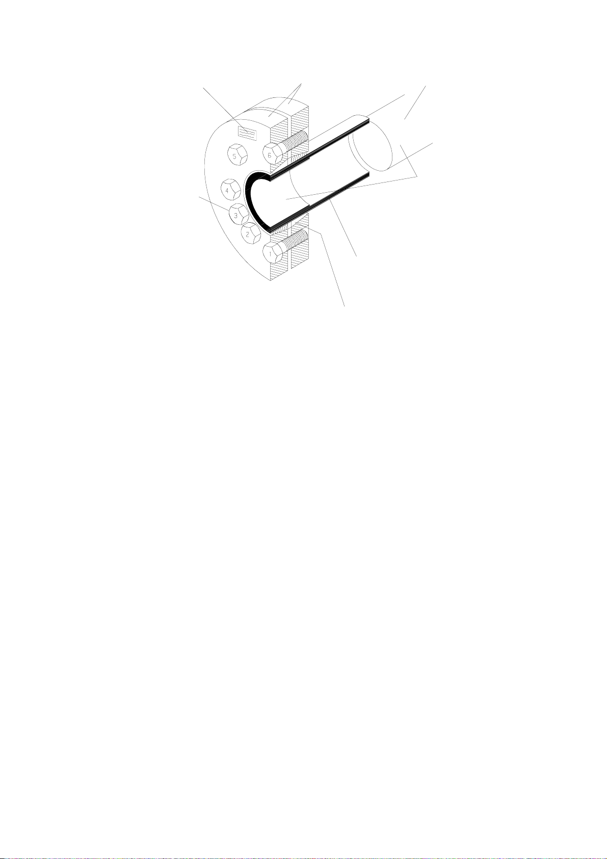
Aufstellung, Vorbereitung
−Transportösen am Getriebe sind für das
Gewicht des Antriebs ausgelegt
−Fundamente ausreichend bemessen und
schwingungsfrei ausführen
−Getriebe oder -motor fest und ohne
Verspannung montieren
−ausreichende Belüftung vorsehen
−serienmäßiges Innengewinde nach DIN 332
zum Aufziehen von Verbindungselementen
auf die Wellen benutzen
−Schläge auf die Wellen vermeiden
(Lagerbeschädigung!)
−Maschine und Getriebe möglichst mit
elastischen Kupplungen verbinden
−vor dem Einschalten Abtriebselemente
aufziehen bzw. Paßfeder sichern
−bei Aufsteckgetrieben mit Drehmoment-
stütze Gummipuffer verwenden
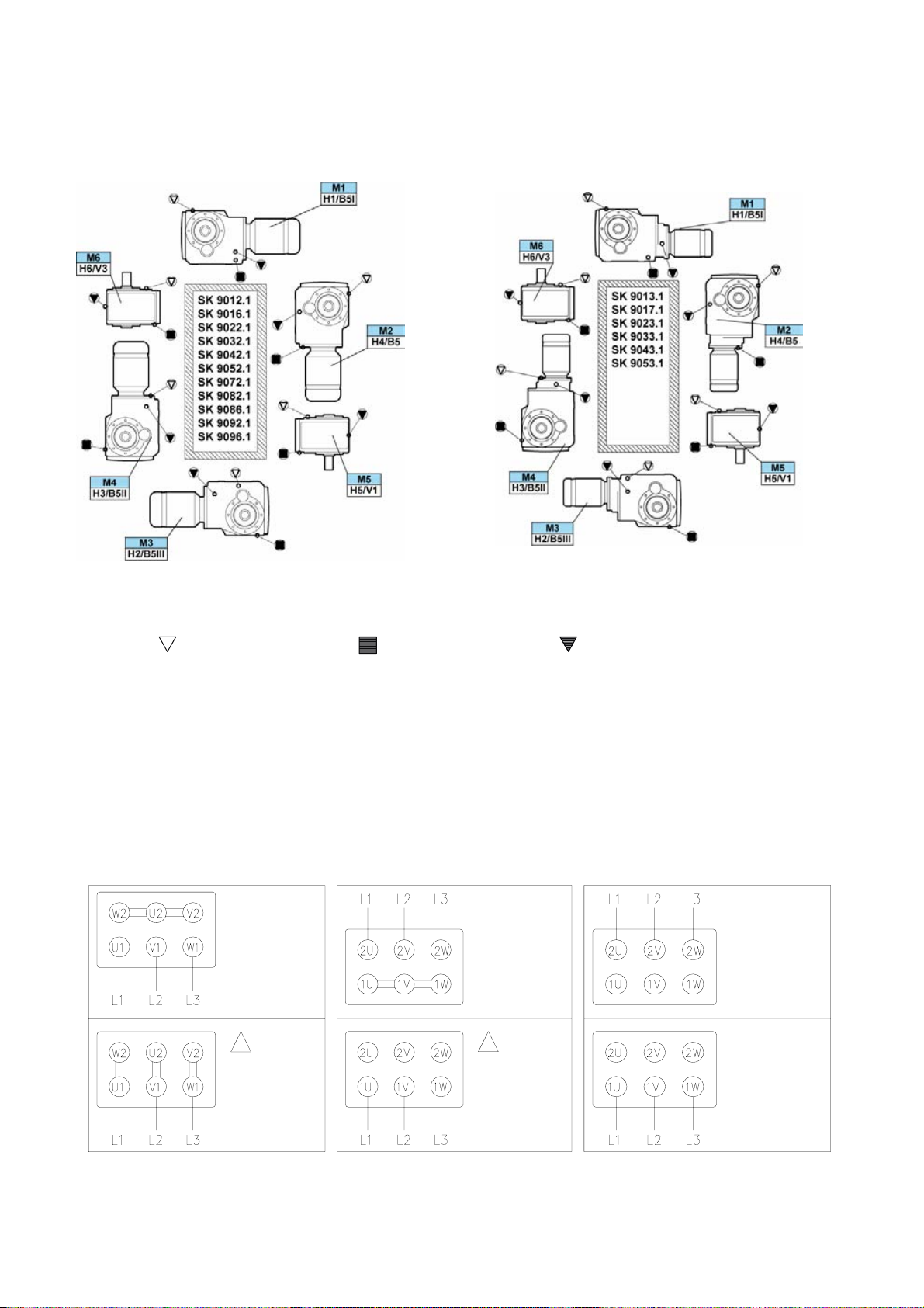
Elektrischer Anschluß
−Motoranschluß nach Schaltbild vornehmen
−Übereinstimmung von Netzspannung und
Frequenz mit den Typenschild-Daten
sicherstellen
−Sichere Schutzleiterverbindung herstellen
−evtl. falsche Drehrichtung korrigieren durch
Vertauschen von 2 Phasen
−Nicht benötigte Kabeleinführungsöffnungen
und den Kasten selbst staub- und
wasserdicht verschließen
−Überbelastung und Phasenausfall durch
Schutzschalter vorbeugen
−Einstellen des Motorschutzschalters auf
Nennstrom
−Schaltbilder auf der letzten Seite
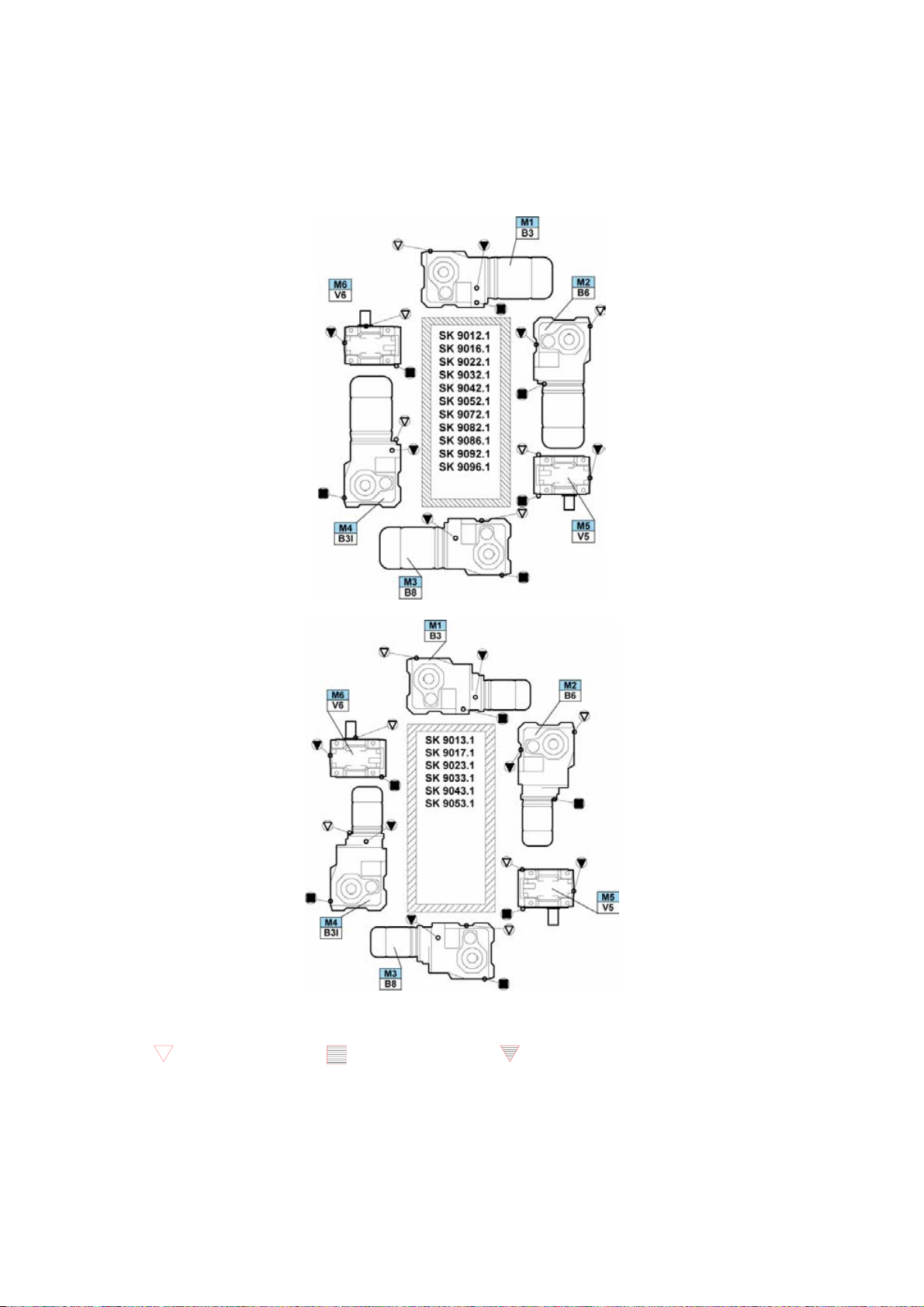
Inbetriebnahme
−bei längeren Lagerzeiten besondere
Vorkehrungen treffen (siehe Werknormblatt
"Langzeitlagerung")
−Lage der Ölstandschraube nach
Bauformtabellen des entsprechenden
Kataloges feststellen
−Prüfen des Ölstandes
−Entfernen des Verschlußstopfens vor
Inbetriebnahme (Überdruck!), ggf. Druck-
entlüftungsschraube montieren
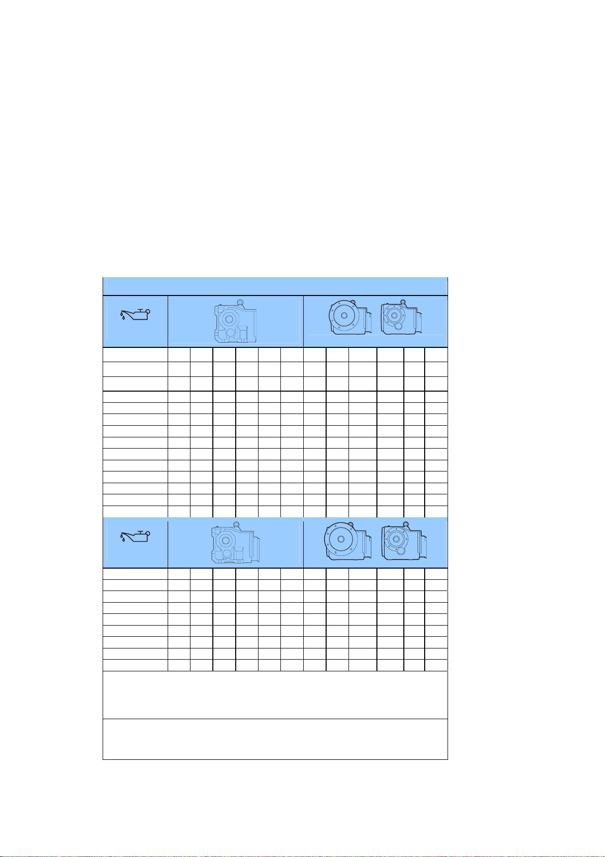
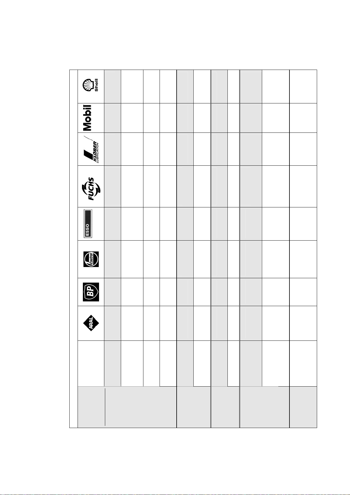
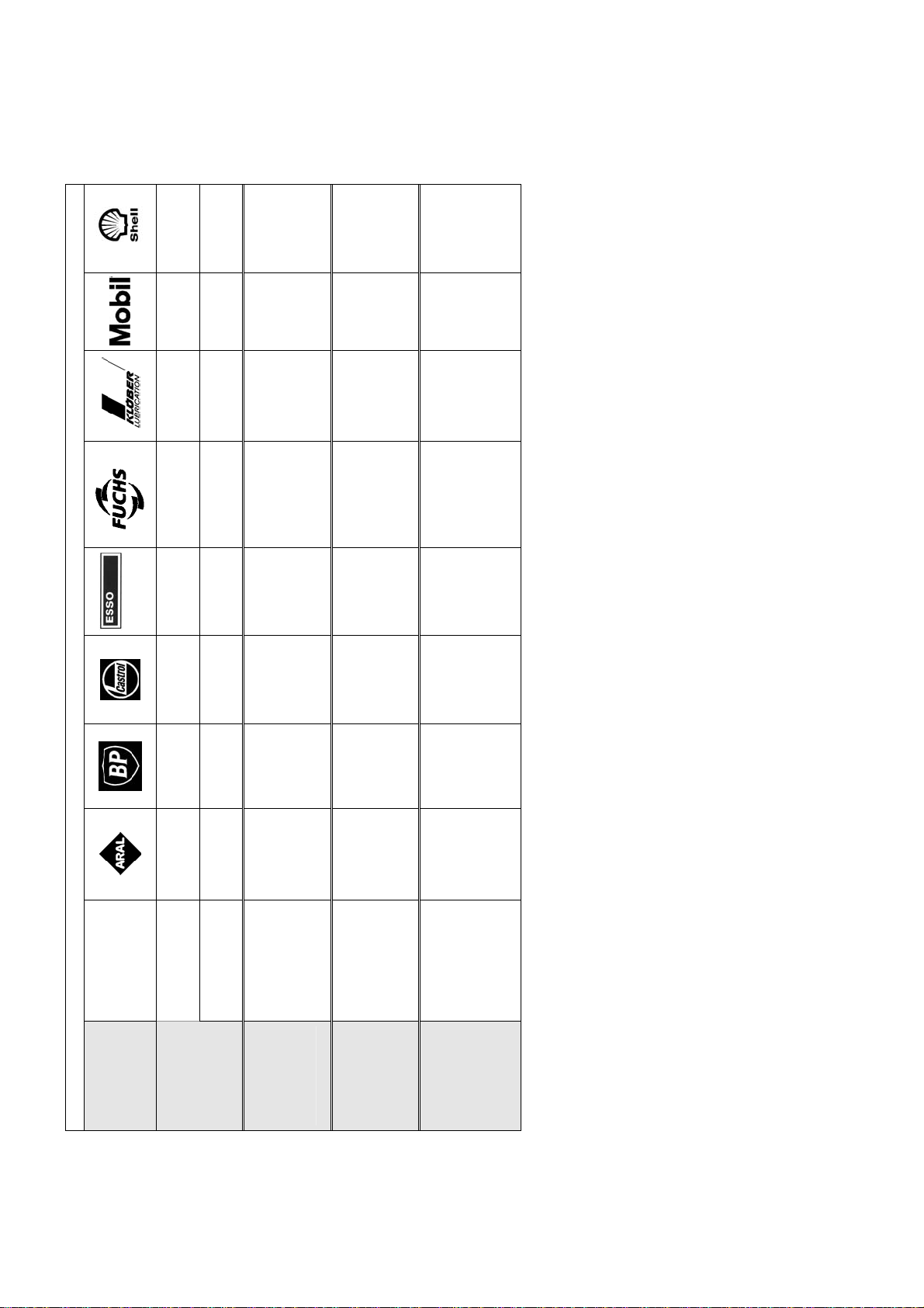
−Normale Erstbefüllung: siehe Schmier-
stofftabelle
−Luftgekühlte Motoren sind für Umgebungs-
temperaturen von - 20°C bis +40°C sowie
Aufstellungshöhen â 1.000 m über NN
ausgelegt
−Der Einsatz im Ex-Bereich ist nicht zulässig,
sofern nicht ausdrücklich hierfür vorgesehen
∆Caution
It is presumed that fundamental project work
as well as all work with regard to transport,
assembly, installation, starting-up,
maintenance and repair is performed by
qualified personnel or supervised by skilled
labour taking overall responsibility. Make
absolutely sure that no voltage is applied at all
while work is being done on the geared motor.
Drive must also be secured against switching
on.
∆Caution
Any deviation from normal operating
conditions (increased power consumption,
temperature, vibrations, noise etc.) or warning
signals by monitoring equipment suggest
malfunction. Inform the responsible
maintenance personnel at once to prevent the
trouble from getting worse and causing,
directly or indirectly, serious physical injury or
material damage.
∆In case of doubt disconnect the machine
immediately!
Preparing and performing installation
−Lifting devices on the drive are designed to
carry the drive weight
−the foundation (base) should be of adequate
size and vibration-proof
−install gear unit or geared motor rigid and
braceless
−ensure sufficient ventilation
−make use of tapped hole (DIN 332) to suit
fastening to the shaft end
−avoid shocks on shafts (bearing damage!)
−preferably use flexible coupling between
output shaft and driven machine
−fit output elements to shaft end or secure
feather key before starting the motor
−use torque arm with rubber buffer on shaft
mounting gearboxes
Connection of motor
−Connect motor according to diagram
−make sure that mains voltage/frequency are
in accordance with nameplate information
−make secure protective conductor conection
−if motor is running in reverse direction,
interchange two phases
−Close unused cable entrances holes and the
box itself in a dust- and watertight manner.
−install protective switches to prevent
overload and phase failure
−set motor protection switch to nominal
current
−wiring diagrams on the last page
Starting up
−in case of long-time storage take special
precautions (as provided in works standard
sheet "Extended Storage")
−check position of oil-level plug with help of
mounting position tables in applicable
catalogue
−check oil-level
−prior to starting-up, remove vent plug from
vent screw if necessary
−if not specified otherwise, first oil filling as is
shown in list of lubricants
−air-cooled motors are designed for ambient
temperautres between -20°C and +40°C and
for installation at altitudes â 1.000 m above
M.S.L.
−Their use in hazardous areas is prohibited
unless they are expressly intended for such
use (follow additional instructions)
∆Avertissement
Il est impératif que les travaux fondamentaux
de l'installation, ainsi que tous les travaux de
transport, montage, installation, mise en
exploitation, entretien et réparation soient
accomplis par du personnel qualifié et
contrólés par des techniciens spécialisés dans
ce domaine. Avant toute intervention sur le
motoréducteur, il faut s'assurer que celui-ci
n'est plus sous tension et que la remise sous
tension soit interdite.
∆Avertissement
Si en utilisation normale, des modifications de
fonctionnement apparaissent telles que
puissance absorbée trop élevée, température
élevée, vibrations fortes, bruit intense etc. ou
en rapport avec les contrôles techniques, cela
laisse supposer que différentes fonctions de
l'appareil peuvent être détériorées. Pour éviter
ensuite des problèmes, qui pourraient
entraîner de graves accidents corporels ou de
graves dégats matériels, le personnel
d'entretien compétent doit immédiatement être
informé.
∆Si vous êtes dans le doute, coupez i
immédiatement l'alimentation!
Mise en place, préparation
−Le matériel utilisé pour la manutention doit
tenir compte du poids de l'équipement
−prendre largement les dimensions des
embases et les réaliser exemptes de
vibrations
−monter les réducteurs et motoréducteurs
solidement et sans haubanage
−prévoir une aération suffisante
−prévoir le taraudage conforme à la norme
DIN 332 pour monter des accouplements sur
les arbres d'entrée et de sortie
−éviter de donner des coups sur les arbres
(cela pourrait détériorer le roulement!)
−lier autant que possible la machine et le
réducteur avec des accouplements
élastiques
−avant la mise en service, enlever l'élément
d'accouplement ou/et fixer la clavette
−utiliser pour l'exécution arbre creux avec
bras de réaction une butée en caoutchouc
Branchements électriques
−brancher le moteur selon le schéma
−s'assurer que la tension du réseau et la
fréquence correspondent aux données
inscrites sur la plaque signalétique
−Le cable de raccordement doit être protégé
−corriger un éventuel mauvais sens de
rotation par une inversion de deux phases
−Les entrées de câbles non utilisées doivent
être obturées, la boîte elle-même devant être
fermée de façon à être étanche à l'eau et à
la poussiére
−prévoir une protection électrique contre les
surcharges, court-circuit et défaut de phases
−régler la protection électrique suivant
l'intensité nominale du moteur
−schéma de branchement à la derniére page
Mise en fonctionnement
−si un stockage longue durée du réducteur
est prévu, il faut prendre les dispositions
nécessaires (voir spécification "Stockage
longue durée")
−vérifier que la vis de niveau d'huile
corresponde à la position de montage du
réducteur (voir catalogue)
−contrôler le niveau d'huile
−enlever la mèche de la vis d'évent avant la
mise en route (pour éviter une surpression)
ou fixer le clapet d'évent sur le réducteur
−pour le premier remplissage voir le tableau
des lubrifiants
−les moteurs autoventilés sont dimensionnés
pour des températures ambiantes comprises
entre -20°C et +40°C, ainsi que pour une
altitude â 1000 mètres au-dessus du niveau
de la mer
−Leur utilisation dans des atmosphères
explosives est interdite, à moins qu'elles ne
soient expressément prévues à cet effet
(respecter les indications supplémentaires)
Wartung
MOTOR
−Staubablagerungen entfernen (Überhitzung!)
−Wälzlager ausbauen, reinigen und einfetten
−Es ist zu beachten, daß der gesamte Freiraum
um das Lager ca. 1/3 mit Fett gefüllt ist
−Schmierstoffsorten siehe unten
GETRIEBE
−regelmäßige Ölstandskontrolle
−Wechseln des Schmierstoffes alle 10.000
Betriebsstunden oder spätestens nach 2
Jahren.
−Doppelte Fristen bei synthetischen Produkten
−Verkürzung der Schmierstoffwechselintervalle
bei extremen Betriebsbedingungen (hohe
Luftfeuchtigkeit, aggressive Umgebung und
hohe Temperaturschwankungen)
−Verbinden des Schmierstoffwechsels mit
gründlicher Reinigung des Getriebes
ΔSynthetische und mineralische Schmier-stoffe
nicht miteinander mischen! Das gilt auch für die
Entsorgung der Schmierstoffe!
Maintenance
MOTOR
−remove dust deposit (overheating)
−dismount anti-friction bearings for cleaning
and refill with grease
−ensure that the bearing cage is packed to
about 1/3 with grease, distribute evenly
−select proper type of lubricating grease from
following table
GEARBOX
−regular oil level check
−change lubricant every 10.000 working hours
or after two years at the latest.
−combine the lubricant change with thorough
cleaning of gear unit
−lubricant changing intervals will be twice as
long if synthetic products are used
−extreme working conditions (high air humidity,
aggressive media and large temperature
variations) call for reduced lubricant changing
intervals
ΔSynthetic and mineral lubricants must not be
mixed either for filling or for disposal!
Entretien
DU MOTEUR
−enlever la poussière du moteur
(échauffement)
−démonter les roulements, les nettoyer et les
regraisser
−la cage des roulements doit être remplie au
1/3 environ
−lubrifiant voir tableau ci-après
DU REDUCTEUR
−vérifier régulièrement le niveau d'huile
−vidanger le lubrifiant après 10.000 heures de
fonctionnement ou au plus tard après 2 ans
d'utilisation.
−profiter de la vidange pour effectuer un
nettoyage approfondi du réducteur
−pour des lubrifiants synthétiques, ce délai peut
être doublé
−réduire les intervalles entre les vidanges dans
des conditions d'utilisation extrêmes
(hygrométrie élevée, ambiance agressive ou
variations importantes des températures)
ΔDes lubrifiants synthétiques et minéraux ne
doivent pas étre mélangés! Ceci s'applique
également pour le retraitement des lubrifiants!
ÖLFÜLLMENGE CAPACITY QUANTITE DE LUBRIFIANT
[L]
M1 M2 M3 M4 M5 M6 M1 M2 M3 M4 M5 M6
B3 B6 B8 B3I
V
5
V
6 B5I B5 B5III B5II
V
1
V
3
H1 H4 H2 H3 H5 H6
SK 9012.1 0,70 1,60 1,90 2,40 1,20 1,70 0,70 1,90 1,90 2,40 1,20 1,70
SK 9016.1 0,70 1,60 1,90 2,40 1,20 1,70 0,70 1,90 1,90 2,40 1,20 1,70
SK 9022.1 1,30 2,60 3,50 4,20 2,00 2,80 1,30 2,60 3,50 4,20 2,00 2,80
SK 9032.1 1,70 4,80 6,40 6,70 4,10 5,10 1,90 5,20 6,40 7,30 3,30 5,10
SK 9042.1 4,40 8,70 10,0 9,80 6,80 7,50 3,60 9,70 11,4 11,5 6,50 8,20
SK 9052.1 6,50 16,0 19,0 21,5 11,0 15,5 7,50 16,5 20,0 22,5 11,5 18,0
SK 9072.1 10,0 27,5 32,0 36,0 18,0 24,0 12,0 27,5 33,0 38,5 19,0 26,0
SK 9082.1 17,0 51,5 62,5 71,5 33,0 46,5 21,0 54,0 66,0 80,0 38,0 52,0
SK 9086.1 29,0 73,0 85,0 102 48,0 62,0 36,0 78,0 91,0 101 53,0 76,0
SK 9092.1 41,0 157 170 172 80,0 90,0 40,0 130 154 175 82,0 91,0
SK 9096.1 98,0 187 194 254 109 152 98 187 193 257 113 156
[L]
M1 M2 M3 M4 M5 M6 M1 M2 M3 M4 M5 M6
B3 B6 B8 B3I
V
5
V
6 B5I B5 B5III B5II
V
1
V
3
H1 H4 H2 H3 H5 H6
SK 9013.1 1,20 2,00 2,20 3,00 1,40 1,90 1,20 2,30 2,20 3,00 1,40 1,90
SK 9017.1 1,20 2,00 2,20 3,00 1,40 1,90 1,20 2,30 2,20 3,00 1,40 1,90
SK 9023.1 2,40 3,00 3,80 5,30 2,20 3,10 2,40 3,00 3,80 5,30 2,20 3,10
SK 9033.1 3,30 6,60 7,00 7,80 4,30 5,10 3,80 5,70 6,90 8,50 3,60 5,60
SK 9043.1 4,60 10,2 10,7 12,8 5,20 6,70 5,70 10,2 14,7 14,7 6,60 9,60
SK 9053.1 10,0 17,0 20,0 24,2 11,5 16,5 12,5 18,0 26,5 21,5 13,0 17,0
Die Normalbefüllung der Getriebe ist Mineralöl. Synthetisches Öl ist gegen Mehrpreis lieferbar.
Standard lubricant for the gearboxes is mineral-oil. Synthetic oil is available at a surcharge.
Les réducteurs sont remplis d’huile minérale. Ils peuvent être remplis d’huile synthétique contre supplément
de prix.
HINWEIS / REMARK / REMARQUE:
Ölfüllmengen sind ca.Angaben. Ölniveau anhand der Ölkontrollschraube prüfen.
Filling quantities are approx. figures. Oil level must be checked according to oil-level plugs.
Les quantités d`huile sont données à titre indicatif. Vérifier la quantité d’huile grâce à la vis de
niveau d’huile.

Hinweis:
Diese Tabelle stellt vergleichbare Schmierstoffe unter-
schiedlicher Hersteller dar. Innerhalb einer Viskosität und
Schmierstoffsorte kann der Ölhersteller gewechselt werden.
Beim Wechsel der Viskosität bzw. der Schmierstoffsorte muß
Rücksprache mit uns gehalten werden, da sonst keine
Gewährleistung für die Funktionstüchtigkeit unserer Getriebe
übernommen werden kann.
Note:
This table lists compatible lubricants of different suppliers.
Within the same viscosity class and type of lubricant the
supplier can be chosen freely. In case you change the
viscosity class resp. the type of lubricant you should contact
us in advance as otherwise we cannot assure the proper
function of our drive and the warranty becomes void.
Indication:
Ce tableau présente les lubrifiants comparables des
différents fabricants. Si l'on respecte les critères de viscosité
et le type de lubrifiant, on peut uiliser n'importe quelle marque
d'huile après ne vidange. Afin de pouvoir garantir un bon
fonctionnement de nos réducteurs, veuillez nous consulter
avant de remplacer un lubrifiant par un autre possédant des
caractéristiques différentes de viscosité et de type.
Schmierstoffarten / Type of lubricant / Type de lubrifiant
Umgebungstemp.
Ambient temp.
Temp. ambiante
Schneckengetriebe
0 ... 40°C
ISO VG 680
Degol BG 680
Degol BG 680
plus
-- Alpha SP 680 Spartan
EP 680 Renolin
CLP 680
CLP 680 Plus
Klüberoil
GEM 1-680N Mobilgear:
- 636
- XMP 680
Shell
Omala 680
ISO VG 220
- 5 ... 40°C (normal)
Degol
BG 220
BG 220 plus
Energol
GR-XP
220
Alpha SP 220
Alpha MW220
Alpha MAX 220
Spartan
EP 220 Renolin CLP 220
Renolin CLP 220
Plus
Klüberoil
GEM 1-220N Mobilgear
630
Mobilgear
XMP 220
Shell
Omala 220
ISO VG 100
- 15 ... 25°C
Degol
BG 100
BG 100 plus
Energol
GR-XP
100
Alpha SP 100
Alpha MW 100
Alpha MAX 100
Spartan
EP 100 Renolin CLP 100
Renolin CLP 100
Plus
Klüberoil
GEM 1-100N Mobilgear:
- 627
- XMP 110
Shell
Omala 100
Schmierstoffart
Type of
lubricant
Type de
lubrifiant
Mineralöl
Mineral oil
Huile minérale
ISO VG 15
- 45 ... - 15°C *
Vitamol
1010 Bartran
HV 15 Hyspin AWS 15
Hyspin SP 15
Hyspin ZZ 15
Univis J13 Renolin B 15 HVI ISOFLEX MT
30 ROT Mobil DTE
11 M Shell Tellus
T 15
Schneckengetriebe
-5 ... 60°C
ISO VG 680
Degol
GS 680 Energol
SG-XP 680 -- -- Renolin PG 680 Klübersynth
GH 6-680 Glygoyle
HE 680 Shell Tivela
S 680
Synthetisches Öl
Synthetic oil
Huile synthétique ISO VG 220
-25 ... 80°C *
Degol
GS 220 Enersyn
SG-XP 220 Alphasyn
PG 220 Glycolube
220 Renolin PG 220 Klübersynth
GH 6-220 Glygoyle
HE 220 Shell
Tivela S 220
Schneckengetriebe
ISO VG 680
-5 ... 40°C
-- -- -- -- Plantogear 680 S -- --Biologisch
abbaubares Öl
Biodegradable oil
Huiles
biodégradables ISO VG 220
-5 ... 40°C Degol
BAB 220 Biogear
SE 220 Carelub
GES 220 -- Plantogear 220 S Klübersynth
GEM 2-220 -- Shell Omala
EPB220
Schneckengetriebe
-5 ... 40°C
ISO VG 680
-- -- -- -- Geralyn
SF 680 Klüberoil
4 UH1-680N
Klübersynth
UH1 6-680
Mobil
DTE-FM
680
Shell Cassida
Fluid GL680
Shell Cassida
Fluid WG680
Eural
Gear 220 -- Vitalube
GS 220 Gear Oil
FM 220 Geralyn
AW 220 Klüberoil
4 UH1-220N Mobil DTE
FM 220 Shell Cassida
Fluid GL220
Shell Cassida
Lebensmittel-
verträgliches Öl 1)
Food-grad oil 1)
Huiles pour
environnement
alimentaire 1)
ISO VG 220
-25 ... 40°C
Geralyn
SF 220 Klübersynth
UH1 6-220 Fluid WG220
Synth. Fließfett
Synth. fluid
grease
Graisse fluide
synthétique
- 25 ... 60°C Aralub
BAB EP0 -- Alpha Gel 00 Fließfett
S 420 Renolit
LST 00 Klübersynth
GE 46-1200
Klübersynth
UH1 14-
16001)
Glygoyle
Grease 00 Tivela GL 00
Schmierstoffarten für Wälzlager / Type of lubricant for anti friction bearings / Type de librifiant pour roulements à rouleaux
Schmierstoffart
Type of
lubricant
Type de
lubrifiant
Umgebungstemp.
Ambient temp.
Temp. ambiante
- 30 ... 60°C
(normal)
Aralub
HL 2 Energrease
LS 2 Spheerol AP
2 LZV-EP Mehr-
zweckfett
Beacon2
Renolit FWA 160 Klüberplex
BEM 41-132 Mobilux 2Fett
(Mineralölbasis)
Grease (mineral
oil basis)
Graisse (base
huile minérale)
* - 50 ... 40°C Aralub
SEL 2 -- Spheerol
EPL2 -- Renolit JP 1619 -- -- Shell Alvania
RL 2
Synthetisches
Fett
Synthetic grease
Graisse
synthétique
* - 25 ... 80°C Aralub
SKL 2 -- Product
783/46 Beacon
325 Renolit S 2
Renolit HLT 2 ISOFLEX
TOPAS
NCA 52
PETAMO
GHY 133 N
Mobiltemp
SHC 32 Aero Shell
Grease
16 oder 7
Biologisch
abbaubares Fett
Biodegradable
Grease
Graisse
biodégradables
- 25 ... 40°C Aralub
BAB EP 2 BP Bio-
grease EP 2 Biotec -- Plantogel 2 S
Klüberbio
M 72-82 Schmierfett
UE 100 B Shell
Alvania
RLB 2
Lebensmittelver-
trägliches Fett 1)
Food-grade
grease1)
Graisse pour
environnement
alimentaire 1)
- 25 ... 40°C Eural
Grease EP 2 BP
Energrease
FM 2
Vitalube HT
Grease 2 Carum
330 Renolit
G 7 FG 1 Klübersynth
UH1 14-151 Mobil-
grease
FM 102
Shell Cassida
RLS 2
*Bei Umgebungstemperaturen unterhalb -30°C und oberhalb 60°C sind Wellendichtringe in besonderer Werkstoffqualität einzusetzen
* With ambient temperatures below -30°C and above approx. 60°C shaft sealing rings of a special material quality must be used
*Lors d’une température ambiante inférieure à -30°C ou supérieure à environ 60°C, il y a lieu d’utiliser des joints d’étanchéité spéciaux
1) Lebensmittelverträgliche Öle + Fette nach Vorschrift H1 / FDA 178.3570
1) Food grade lubricants with USDA-H1 approval FDA 178.3570
1) Huiles pour environnement alimentaire + graisses suivant prescription H1 / FDA 178.3570
Hohlwelle mit Schrumpfscheibe - Montage - Demontage und Wartungshinweise
Hollow shaft with shrink-discs - Assembly - Dismantling suggestions and maintenance
Exécution des arbres creux avec frette de serrage - Montage - Démontage et entretien
Montageablauf:
1. Entfernen der Transportsicherung zwischen den
Flanschen, falls vorhanden.
2. Anziehen der Spannschrauben (leicht von Hand) bis
das Spiel zwischen den Flanschen und dem Innenring
beseitigt ist. Der Innenring muß noch leicht drehbar
sein.
3. Einfetten der Bohrung des Innenringes, dadurch
leichte Montage der Schrumpfscheibe auf die
Getriebehohlwelle.
4. Aufsetzen der Getriebehohlwelle auf die
Maschinenwelle.
Maschinenwellenschaft und Hohlwellenbohrung
müssen im Bereich der Schrumpfverbindung
a b s o l u t f e t t f r e i sein.
Die Maschinenwelle vor der Montage im Bereich,
welche später Kontakt mit der Bronzebuchse der
Hohlwelle hat, einfetten. Die Bronzebuchse nicht
einfetten, um bei der Montage eine Befettung des
Schrumpfsitzes zu vermeiden.
5. Durch leichtes Anziehen der Spannschrauben
positionieren sich die Spannflansche automatisch.
6. Festziehen der Spannschrauben der Reihe nach im
Uhrzeigersinn über mehrere Umläufe - nicht
überkreuz - 1/4 bis 1/2 Schraubenumdrehung pro
Umlauf.Die Spannschrauben mit einem Drehmoment-
schlüssel bis zu dem auf der Schrumpfscheibe oder in
der Maßtabelle angegebenen Anzugsdrehmoment
anziehen.
Demontageablauf:
1. Spannschrauben der Reihe nach über mehrere
Umläufe lösen, pro Umlauf ca. 1/4 Umdrehung.
Spannschrauben nicht aus ihrem Gewinde entfernen -
Unfallgefahr!!
2. Die Spannflansche sind vom Konus des Innenringes
zu lösen.
3. Abnehmen des Getriebes von der Maschinen-
vollwelle.
Wartung der Schrumpfscheiben:
Eine montierte Schrumpfscheibe ist wartungsfrei. War
eine Schrumpfscheibe längere Zeit im Einsatz und
wurde demontiert, dann ist sie vor der erneuten Montage
zu zerlegen und zu reinigen. Nach der Reinigung sind
die Kegelflächen (Konus) der Spannflansche und des
Innenringes mit Molykote G-Rapid Plus oder
vergleichbarem Schmierstoff einzustreichen. Die
Schrauben sind im Gewinde und Kopfauflage mit
normalem Fett zu behandeln.
Installation instructions:
1. Remove transportation spacers (if provided) located
between outer collars.
2. Lightly handtighten locking screws to eliminate play
between outer collars and inner ring. You should still
be able to easily turn inner ring.
3. Lightly lubricate the bore of the shrink-disc to facilitate
easy mounting onto hollow-shaft of reducer.
4. Fit shrink-disc onto hollow-shaft and mount hollow-
shaft reducer onto solid shaft.
Hollow- and solid shaft must be clean and
f r e e f r o m a n y l u b r i c a n t .
Exception: Grease solid shaft at end where it will
make contact with bronze bushing of the hollow-
shaft when it is mounted. N e v e r g r e a s e the
front of the solid shaft which makes contact under
the shrink-disc. Tighten locking screws only after
mounting the hollowshaft onto the solid shaft.
5. Now tighten locking screws only lightly to position
outer collars.
6. Use torque wrench and equally tighten all screws one
after another (never cross wise) in a clockwise or
counter clockwise sequence by approximately 1/4 to
1/2 turn until specified tightening torque (per table) is
reached.
Removal:
1. Loosen locking screws in sequence in several steps
by using approximately 1/4 turns. Danger - Do not
remove locking screws completely.
2. Loosen the outer collars from the double tapered inner
ring.
3. Remove hollow-shaft reducer from solid shaft.
Maintenance:
An installed shrink-disc is maintenance free. Before
reinstalling (after prolonged use) it should be taken apart
and thorougly cleaned. Relubricate the taper of the outer
collars and of the inner ring with Molycote G-Rapid plus
or equivalent. Regrease screw threads and head contact
area with mulitpurpose grease.
Procédure de Montage:
1. Les éventuelles protections de transport placées entre
les surfaces de serrage doivent être retirées.
2. Les vis de serrage doivent être légèrement serrées à
la main, jusqu'à ce qu'il n'y ait plus de jeu entre les
surfaces de serrage. L'anneau intérieur doit toutefois
pouvoir encore être tourné aisément.
3. L'alésage (D1) de la bague intérieure de la frette doit
être légèrement graissé. De la sorte, le montage de la
frette sur l'arbre creux est facilité.
4. Positionner l'arbre creux réducteur sur l'arbre
machine.
L'arbre machine et l'arbre creux doivent absolument
être e x e m p t - de - g r a i s s e - au niveau de la
liaison par frette.
Préalablement au montage, l'arbre machine doit être
graissé à l'endroit du position-nement prévu de la
bague bronze de l'arbre creux. N e p a s g r a i s s
e r la bague bronze, pour éviter un graissage du
siège de la frette lors du montage.
5. Serrer légèrement les vis de serrage de la frette, afin
que les surfaces de serrage se positionnent
automatiquement.
6. Serrer les vis dans le sens des aiguilles d'une montre
les unes après les autres, en plusieurs fois, en faisant
à chague fois d' 1/4 à 1/2 tour de vis. Ne pas serrer en
diagonale! Utiliser une clef dynamométrique pour le
serrage. Les couples de serrage sont indiqués sur les
frettes, ou doivent être relevés sur les plans.
Procédure de démontage:
1. Les vis de serrage doivent être desserrées dans
l’ordre, les unes après les autres, en plusieures fois,
avec environ 1/4 de tour par vis à chaque fois. Ne pas
sortir les vis du filetage. Risque d’accident!!
2. Le plan de serrage doit être écarté du cône de la
bague intérieure.
3. Retirer le réducteur de l’arbre machine.
Entretien des frettes de serrage:
Une frette de serrage montée ne nécessite aucun
entretien. Si une frette utilisée depuis un certain temps
est demontée, un nettoyage préalable à toute nouvelle
utilisation est nécessaire. Après nettoyage, les surfaces
coniques de serrage et la bague intérieure doivent être
enduites de Molykote G-Rapid Plus ou d’un type de
graisse analogue. Les filetages et têtes de vis doivent
être graissés normalement.
Schrumpfscheibentyp, Sach-Nr. und Drehmomentangabe für Spannschrauben
Shrink-disc type, part-no. and torque of locking screws
Indication du type de frette et du couple de serrage et no. ident.
Spannflansche
Locking hub
disques de serrage Vollwelle der Maschine
Customers solid shaft
arbre plein machine
Wellenschaft und Hohlwellenbohrung
Solid shaft and bore of hollow shaft
arbre et alésage arbre creux
FETTFREI
GREASE-FREE
SANS GRAISSE
Hohlwelle des Getriebes
Hollow-shaft (Gearbox)
arbre creux du réducteur
Zweimal halbgeschlitzter Innenring
Dual half-split Inner ring
deux bagues intérieures fendues
Spannschrauben DIN 931 (933) -10.9
Locking screws DIN 931 (933) -10.9
Vis de serrage DIN 931 (933) -10.9
Die Schrumpfscheiben werden vom Hersteller einbaufertig
geliefert. Sie sollen vor der Montage nicht mehr auseinander-
genommen werden.
Shrink-discs are supplied ready for installation and should not be
taken apart before mounting.
Les frettes de serrage sont livrées prêtes à monter par le
fabricant et ne doivent donc pas être démontées avant le
montage.
BAUFORMEN
MOUNTING POSITIONS
POSITIONS DE MONTAGE
Symbole:
Symboles:
Symboles:
Entlüftung
Vent plug
Event
Ölablaß
Drain plug
Vidange
Ölstand
Oil level
Niveau d’huile
Mat.-Nr. 605 07 99 / 0208
Drehstrommotor
Three phase motor
Moteur triphasé
Drehstrommotor, polumschaltbar
Dahlanderschaltung
Three phase motor, polechanging,
Dahlander connection
Moteur triphasé à commutation de
pôles, couplage Dahlander
Drehstrommotor, polumschaltbar
getrennte Wicklungen
Three phase motor, polechanging,
separate windings
Moteur triphasé à commutation de pôles,
bobinages séparés
Entlüftung
Vent plug
Event
Ölablaß
Drain plug
Vidange
Ölstand
Oil level
Niveau d’huile
Symbole:
Symboles:
Symboles:
BAUFORMEN
MOUNTING POSITIONS
POSITIONS DE MONTAGE
hohe
Spannung
high voltage
tension
supérieure
Y
niedrige
Spannung
low voltage
tension
inférieure
hohe
Drehzahl
high speed
grande
vitesse
niedrige
Drehzahl
low speed
petite
vitesse
Y
hohe
Drehzahl
high speed
grande
vitesse
niedrige
Drehzahl
low speed
petite
vitesse
Schaltbilder / Wirin
g
dia
g
ram / Schémas de branchement

This manual suits for next models

16

Other nord Industrial Equipment manuals

nord B 1050 Product guide

nord

nord B 1050 Product guide

nord SK CI5-230/006-C User manual

nord

nord SK CI5-230/006-C User manual

nord NORDAC FLEX SK 2x5E User manual

nord

nord NORDAC FLEX SK 2x5E User manual

nord SK 7207 Manual

nord

nord SK 7207 Manual

nord MAXXDRIVE Product guide

nord

nord MAXXDRIVE Product guide

nord Power Genius 3000 User manual

nord

nord Power Genius 3000 User manual

nord B 1040 Manual

nord

nord B 1040 Manual

Popular Industrial Equipment manuals by other brands

Grizzly G0526A40 owner's manual

Grizzly

Grizzly G0526A40 owner's manual

ITT Industries FLYGT 4610 Workshop manual

ITT Industries

ITT Industries FLYGT 4610 Workshop manual

PCB Piezotronics IMI SENSORS 080M470 Installation and operating manual

PCB Piezotronics

PCB Piezotronics IMI SENSORS 080M470 Installation and operating manual

WEDGELOCK TenX Coupler owner's manual

WEDGELOCK

WEDGELOCK TenX Coupler owner's manual

Pepperl+Fuchs LS684 Series manual

Pepperl+Fuchs

Pepperl+Fuchs LS684 Series manual

irritec Rotodisk IU4304 Operating and maintenance instructions

irritec

irritec Rotodisk IU4304 Operating and maintenance instructions

Pepperl+Fuchs MLV11 Series manual

Pepperl+Fuchs

Pepperl+Fuchs MLV11 Series manual

handtmann 09513 operating manual

handtmann

handtmann 09513 operating manual

Toku TMH Series instruction manual

Toku

Toku TMH Series instruction manual

Allen-Bradley 1492-P installation instructions

Allen-Bradley

Allen-Bradley 1492-P installation instructions

Eaton PowerPass 9PXTFMR5 user guide

Eaton

Eaton PowerPass 9PXTFMR5 user guide

TRAK VMC12si Site preparation guide

TRAK

TRAK VMC12si Site preparation guide

Adp UHRS-030A installation instructions

Adp

Adp UHRS-030A installation instructions

Vega POINTRAC 31 operating instructions

Vega

Vega POINTRAC 31 operating instructions

WPG N Series instructions

WPG

WPG N Series instructions

COREMO OCMEA ID 2500N User and maintenance manual

COREMO OCMEA

COREMO OCMEA ID 2500N User and maintenance manual

Siemens 8UD1 1 A Series operating instructions

Siemens

Siemens 8UD1 1 A Series operating instructions

DMC SuperSigma2 Quick reference manual

DMC

DMC SuperSigma2 Quick reference manual

manuals.online logo
manuals.online logoBrands
  • About & Mission
  • Contact us
  • Privacy Policy
  • Terms and Conditions

Copyright 2025 Manuals.Online. All Rights Reserved.