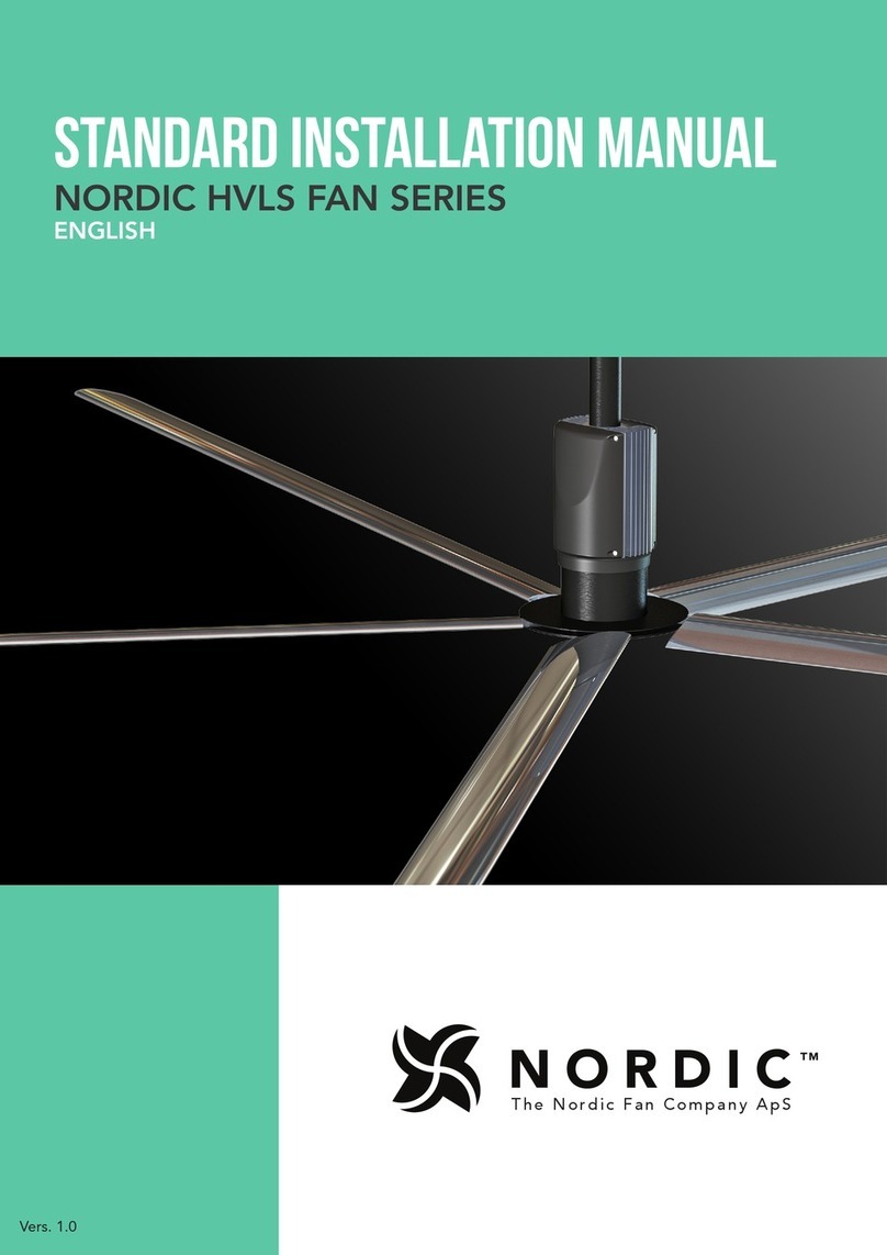
Nordic HVLS Series User manual

1
The Nordic Fan Company ApS
INSTALLATION MANUAL
EXTRA MOUNTING OPTIONS
NORDIC HVLS FAN SERIES
ENGLISH
Vers. 1.0

2
The Nordic Fan Company ApS
Contents
General Safety Information, Pre-installation checks ....................................................................... 3
Required Tools & Accessories ........................................................................................................ 4
Extra Mounting option for Wood & Concrete Beams ................................................................... 5
Mounting Brackets for Steel-beam ................................................................................................. 6
Continue Installing the Fan ............................................................................................................. 7
The NORDICTM HVLS Fan Series is a
230V/50Hz ‘Plug & Play’ solution. It is
the ideal choice for providing year-round
comfort in air circulation and de-strat-
ification applications. Featuring an
aerodynamic air blade design and a high
efficiency direct drive motor, the
NORDIC HVLS Fan Series delivers
maximum airflow at a fraction of the
operating cost of other HVLS fans. With
its universally designed ceiling mount it is
optimised for simple plug-and-play instal-
lations, making it the easiest HVLS fan to
install on the market.
NORDIC HVLS Series
INSTALLATION INFO:
If you cannot install the NORDICTM Fan using only the Standard Swivel mount, then you
can utilize one of the additional mounting options, as described in this manual.

3
The Nordic Fan Company ApS
1. Verify that the fan is to be installed in a location where the airblades will be a minimum of 3,0 meters above the finished floor with
a minimum of 1,2 meter of clearance to any obstructions.
2. If the building has a mezzanine or other elevated spaces that may be occupied by people, verify that no component of the fan can
be reached from the highest level or deck. The fan must be positioned so that the tips of the airblades are a minimum of 1,2 meter
away from the furthest point that a person could extend an appendage outward.
3. Check that the fan will not be mounted in a location near overhead doors or other building openings where gusts of wind may
occur. Fans should not be installed or operated in locations where wind is present.
4. If the building is equipped with a fire sprinkler system, verify that the placement of the fan will not interfere with correct sprinkler
operation and that the fan installation complies with all building codes.
5. Check to see if the intended placement of the fan is directly below any building lights or skylights. If possible, avoid installing fans
directly below a light source to prevent a strobing effect that can be caused by fan rotation.
6. For best performance, the fan must be installed with a two-fan diameter minimum clearance to radiant heaters and HVAC system
discharges or intakes.
7. BEFORE INSTALLATION, IT IS IMPORTANT TO VERIFY THE MOUNTING SURFACE WILL BEAR THE OPERATING WEIGHT
AND MAXIMUM TORQUE (TWISTING FORCE) OF THE TO-BE-INSTALLED NORDIC™ SYSTEM. IT IS THE SOLE RESPON-
SIBILITY OF THE INSTALLER TO ENSURE THAT THE MOUNTING STRUCTURE AND FAN INSTALLATION METHOD ARE
ADEQUATE FOR SAFE OPERATION OF THE NORDIC™ FAN.
MAX TORQUE PER NORDIC™ FAN SIZE
Fan size (meter) 1,8 2,4 3,1 3,7 4,3
Max. torque (Nm) 8,4 13,0 28,2 43,1 54,8
8. THE FIXING MEANS FOR THE ATTACHMENT TO THE CEILING SHALL BE FIXED WITH A SUFFICIENT STRENGTH TO WITH-
STAND FOUR (4) TIMES THE WEIGHT OF THE SPECIFIC NORDIC™ CEILING FAN (SEE ALSO TABLE BELOW).
NORDIC™ SYSTEM F13-1,8M F13-2,4M F13-3,1M F13-3,7M F13-4,3M
HANGING WEIGHT 31kg 34kg 37kg 39kg 41kg
9. INSTALLATION AND MAINTENANCE ARE TO BE PERFORMED BY QUALIFIED PERSONNEL ONLY, FAMILIAR WITH
LOCAL REGULATIONS AND EXPERIENCED WITH THIS TYPE OF EQUIPMENT.
Pre-installation checks
To reduce the risk of fire, electric shock, or injury to persons, observe the following:
1. Use this unit only in the manner intended by the manufacturer. If you have questions, contact the Nordic Fan Company or its
representative.
2. Before servicing or cleaning the unit, switch power off at service panel and lock the service disconnecting means to prevent
power from being switched on accidentally.
3. Installation work and electrical wiring must be done by qualified person(s) in accordance with all applicable codes and stan-
dards.
4. DO NOT ALLOW WATER OR SOLVENTS TO ENTER THE MOTOR OR THE DRIVE. UNDER NO CIRCUMSTANCES SHOULD
MOTORS OR DRIVES BE SPRAYED WITH STEAM, WATER OR SOLVENTS.
5. It is highly recommended that an emergency disconnect switch is installed between each NORDIC™ fan and the electrical mains.
Ensure that such a switch is NOT located directly above air blades, so that it can be accessed at all times - even when fan is operating.
General Safety Information
WARNING
IMPORTANT: Consult all applicable rule and codes to ensure that all necessary requirements are met. It is the sole responsibil-
ity of the installer to ensure compliance with applicable codes.

4
The Nordic Fan Company ApS
required Tools & accessories
10,13 & 17 MM
WRENCH
LEVEL DRILL
SOCKET
WRENCH
LIFT OR
SCAFFOLDING
4 MM
ALLEN KEY
10,13 & 17 MM
WRENCH SOCKET
PREPARING UPPER MOUNT PLATE
First, attach the swivel mount to the
upper mount plate using countersunk
screws. The countersunk side is placed
in the designated hole on the upper
mount plate, facing downwards, to
maintain a flat surface of the upper
mount plate.
On the other side of the mount plate,
place the swivel mount, followed by
washers and finally locknuts on each
bolt.
Tighten the bolts, so the swivel mount
is locked tight to the upper mount
plate.
Now you can install the upper mount
plate on wood, concrete or steel
beams.
REQUIRED SCREWS AND BOLTS
COUNTERSUNK SCREWS
FOR SWIVEL MOUNT
4 pcs. 6x20 mm.
4 washers, 4 locknuts
NO DRILL BIT NEEDED

5
The Nordic Fan Company ApS
EXTRA MOunting options
For concrete mounting:
Using L-shaped shim plates as a tem-
plate, predrill 5mm holes in concrete
beam.
Bolt the L-shaped shim plates into pla-
ce using specified screws for concrete
mounting.
For wood mounting:
Attach L-shaped shim plates to wood
beam using specified screws for wood
mounting.
Note
Be sure bottom of shim plates are
flush or slightly below bottom of
beam to effectively connect to the
upper mount plate.
The upper mount plate can accom-
modate beam widths between 80 -
225 mm
When L-shaped shim plates are instal-
led, line up the upper mount plate and
bolt into L-shaped shim plates using
specified bolts, washers and locknuts
as seen on Figure A.
Tighten thoroughly and continue fan
installation as described in the Stan-
dard Installation Manual.
MOUNTING OPTION FOR WOOD & CONCRETE BEAMS
REQUIRED SCREWS AND BOLTS
1
Upper mount plate (1x)
L-shaped shim plate (2x)
1
2
2
Figure A
SCREWS FOR CONCRETE
MOUNTING
8 pcs. HUS3-H 6x80 mm.
SCREWS FOR WOOD
MOUNTING
8 pcs. 6,5x60 mm.
SCREWS FOR MOUNT
PLATE
4 pcs. 10x40 mm.
8 washers, 4 locknuts
DRILL BIT 6MM HSS NO DRILL BIT NEEDED NO DRILL BIT NEEDED

6
The Nordic Fan Company ApS
Placing the upper mount plate below
the I-beam. On each side of the
I-beam, place 1 shim plate and hook
1 clamp plate above I-beam flange, as
shown above and illustrated on Figure B.
Center the upper mount plate under
the steel beam. Tighten using bolts as
specified until upper mount plate and
clamp plates are snug against I-beam.
Ensure the clamp plates have maxi-
mum engagement on both sides and
tighten evenly.
Continue fan installation as described
in the Standard Installation Manual.
MOUNTING BRACKETS FOR STEEL-BEAM
Upper mount plate (1x)
The Upper mount plate can
accommodate I-beams with a
flange width of up to 250mm
Clamp plate (2x)
Shim plate (2x)
1
1
2
2
3
3
Figure B
REQUIRED SCREWS AND BOLTS
SCREWS FOR MOUNT
PLATE
4 pcs. 10x40 mm.
8 washers, 4 locknuts
Other manuals for HVLS Series
3
Table of contents
Other Nordic Fan manuals
Popular Fan manuals by other brands

Maico
Maico DZQ B Series Installation and operating instructions

Kendal Lighting
Kendal Lighting Triax AC-22352 Installation and operation manual

Bionaire
Bionaire BAOF25M instruction manual

Rasonic
Rasonic RLF-9KIT user manual

Ventair
Ventair GYRO 200 Installation, Use and Care Instructions

Hunter
Hunter Stile installation manual

Euromate
Euromate 482235 manual

Monte Carlo Fan Company
Monte Carlo Fan Company 5DIC44XXXD-V1 Series Owner's guide and installation manual

Vornado
Vornado 160 owner's guide

ViM
ViM KUBAIR F400 instruction manual

Panasonic
Panasonic FV-10VEC2RH Service manual

Hunter
Hunter Sea Air Owner's guide and installation manual