Nordmann Engineering MultiPipe User manual

INSTALLATION AND OPERATING INSTRUCTIONS
NORDMANN
ENGINEERING
NORDMANN
ENGINEERING
Dampfluftbefeuchter econoVap
MultiPipe
2557005 EN 1406
Steam distribution system


3
Contents
1 Notes on steam distribution system MultiPipe 4
1.1 MultiPipe – Steam distribution system for very short humidication distance 4
1.2 Positioning of the steam distribution system 4
1.3 Determination of steam absorption distance 5
1.4 Notes on installation 5
2 Notes for the planning engineer 6
2.1 Layout 6
2.2 Dimension diagrams 6
2.3 Power selection diagram MultiPipe Systems 1...4 7
2.4 Type key 7
2.5 Determination of the humidication distance “BN” 8
2.6 Planning data MultiPipe steam distribution system (for faxing!) 8
3 Mounting 9
3.1 Safety 9
3.2 Delivery 9
3.3 Mounting positions 9
3.4 Mounting the premounted MultiPipe system 10
3.5 Mounting the different parts of the MultiPipe system 11
3.6 MultiPipe Support (accessory) 12
4 Putting into operation and operation 13
4.1 Putting into operation 13
4.2 Operation 13
5 Spare parts list 14

4
1.1 MultiPipe – Steam distribution system for very short humidication distance
The MultiPipe is made from stainless steel and high-grade plastic compo-
nents. It is designed for con nection to the Nordmann steam humidi ers.
The MultiPipe steam distribution system is installed directly in the air duct
or in an air-handling unit. It comprises horizontal collector pipes and several
vertical pipes provided with steam nozzles. The MultiPipe separates the
condensate from the inlet steam and feeds this uniformly and drip-free to
the air ow. In particular the steam ab sorption distance is considerably less
compared with conventional steam distribution pipes.
Note: To ensure a safe support of the collector pipes we recommend the
use of the specially designed support for the steam distribution system
MultiPipe. The entire support is made from stainless steel and available in
four different mounting sets for duct heights ranging from 450 to 3200 mm
(see table in chapter 3.6). The mounting sets comprise all necessary parts
for the correct support of a MultiPipe system.
1.2 Positioning of the steam distribution system
The positioning of the steam distribution system should be determined when
laying out the air-con-ditioning system. The following points should be ob-
served to en-sure correct humidication of the air. The conditions must be
main tained exactly to ensure that the MultiPipe system satises the high
demands made of it. A layout based on incorrect data, an unfavourable
installation position or wrong installation can result in excessive humidity
with separation of condensate and therefore to damage from water. The air
duct must therefore be sealed in the area of the absorption distance and
provided with a water drainage tray with outlet. The system is preferably t-
ted immediately following the air heater (and before the cooling coils). Other
installation situations require additional care. A viewing port immediately
following the system is highly recommended for installation and inspection
of operation of the installation. Installation of the system is always made
laterally to the air ow. With vertical air ow the nozzle tubes are tted at an
angle of 20° to 30° to enable the condensate to ow away easily.
With exception of determination of the steam absorption distance, the
same basic rules apply to the MultiPipe steam distribution system as to the
standard steam distributor pipes (see installation and operating instructions
of the humidier).
1 Notes on steam distribution system MultiPipe

5
1.3 Determination of steam absorption distance
Determination of the absorption distance “BN” depends on various factors.
For simple determination of the absorption distance “BN” the table can be
used. The nominal values obtained from the table refer to an air inlet tem-
perature of 10 °C to 30 °C. The result must be compared with the actual
steam absorption distance or with the minimum spacings to be observed.
1.4 Notes on installation
Before installation check that the correct MultiPipe system is used and
that the system is in accordance with the type and steam output on the
specication label.
The MultiPipe is suitable for installation in air ducts or air-conditioning units.
For this purpose the templates supplied are attached to the ventilation duct
spaced according to the collectors. The duct plate is cut out round. The con-
nection side of the pre-tted system is inserted from inside through these
holes. The connector pieces are then t ted on the pipes from outside and
screwed to the duct wall. The collector pipes should be aligned horizontally
and secured at the end on the duct wall.
For large systems or in special cases, where this type of installation is not
possible, the collector pipes can be tted individually from out side. The noz-
zle tubes are then inserted in the collectors in the air duct and secured with
the pipe clamps and O-rings. Suitable pliers are required for the installation.
All parts are supplied loose for this case if required.
Then install the steam and condensate hoses according to the instructions
in the installation and operating instructions of the humidier. It is advisable
to drain the con densate separately and not return it to the humidier owing
to the increased volume.

6
2 Notes for the planning engineer
2.1 Layout
The choice of the MultiPipe steam distribution system can be made from
the layout tables. The system is determined by the number of steam con-
nections of the steam humidier. This also determines the maximum steam
output. The maximum possible collector lengths and collector spacing is
selected depending on the duct width and height.
2.2 Dimension diagrams
90 A L
D1
Ø 30
Ø 60.3
D2
H H
Ø 35.0
D1 D1 D1 D1 60
B
90 A L
D1
Ø 30
Ø 60.3
D2D2 120
H
Ø 35.0
D1 D1 D1 D1 60
B
MultiPipe System 1&2
System 4
MultiPipe System 4
Systems 1 and 2

7
2.3 Power selection diagram MultiPipe Systems 1...4
L mm 350 500 650 800 1000 1200 1500 1800 2000 2300 2500
B min. mm 450 600 750 900 1100 1300 1600 1900 2200 2500 2700
System 1 **
mD max. kg/h 23 32
D2 mm 350 500 650 800 1000 1200 1500
H min. mm 450 600 800 950 1150 1350 1650
System 2 **
mD max. kg/h 45 65
D2 mm 350 500 650 800 1000 1200 1500 1800 2000
H min. mm 450 600 800 950 1150 1350 1650 1950 2200
System 4 ***
mD max. kg/h 90 130
D2 mm 300 375 475 575 725 875 1050 1200 1350 1500
H min. mm 800 950 1150 1350 1650 1950 2300 2600 2900 3200
** Systems 1 and 2 for single units only
*** System 4 for double units only
2.4 Type key
X / XXX / XXX / XXX
No. MultiPipe system
Collector length “L” in [mm]
Collector distance “D2” in [mm]
Steam capacity “mD” in [kg/h]
H
B

8
2.5 Determination of the humidication distance “BN”
Entering humidity
φ 1 in % r.H.
Leaving humidity
φ 2 in % r.H.
40 50 60 70 80 90
50.22 m 0.28 m 0.36 m 0.48 m 0.66 m 1.08 m
10 0.20 m 0.26 m 0.34 m 0.45 m 0.64 m 1.04 m
20 0.16 m 0.22 m 0.30 m 0.41 m 0.58 m 0.96 m
30 0.10 m 0.17 m 0.25 m 0.36 m 0.52 m 0.88 m
40 0.11 m 0.20 m 0.30 m 0.45 m 0.79 m
50 0.13 m 0.24 m 0.38 m 0.69 m
60 0.16 m 0.30 m 0.58 m
70 0.20 m 0.45 m
The length of the absorption distance BNin m
is for ducts with <600 mm about 50% longer
2.6 Planning data MultiPipe steam distribution system (for faxing!)
Layout data required Installation 1 Installation 2 Installation 3 Installation 4
1. Clear height of air duct “B”
(without insulation) mm
2. Clear width of air duct “H”
(without insulation) mm
3. Wall thickness of air duct “A”
(without insulation) mm
4. Air volume per hour or m3/h
5. Air speed m/s
6. Air duct static pressure Pa
7. Temperature after humidication °C
8. Abs. humidity before humidication g/kg
9. Humidity increase (∆x) or g/kg
10. Rel. humidity after humidication %
11. Humidier capacity kg/h
12. Steam humidier selected type
13. Number of steam connections pcs.
14. Following air-cond. components type
15. Existing humidication distance m
MultiPipe System selected type
– Collector length (L) mm
– Collector spacing (D2) mm
– Steam output at 500 Pa (mD) kg/h
Order No.

9
3 Mounting
3.1 Safety
The MultiPipe steam distribution system must only be installed by adequately
qualied personnel.
Observe and comply with all safety instructions in the installation and
operating instructions of the steam humidier.
3.2 Delivery
The MultiPipe steam distribution system will be delivered either premounted or
as single components. Observe the corresponding mounting instructions.
3.3 Mounting positions
The MultiPipe steam distribution system can be installed in horizontal or
vertical ducts. When mounting in a vertical duct the nozzle pipes must
have a minimum declination of 20° and the end pieces of the collector pipes
must be turned, so that the vertical condensate connection directs straight
downwards (see gure below).
Note: Before mounting the MultiPipe system check the type designation
and steam capacity on the data plate to ensure that the correct MultiPipe
system is installed in the right place.
In addition to this installation and operating instructions please observe and
comply with the instructions regarding the steam installation (positioning,
max. length of steam pipe, etc.) in the installation and operating instructions
of the steam humidier.
20°
1x
+70°
–70°

10
3.4 Mounting the premounted MultiPipe system
1. Remove the protection covers.
2. Measure the distance of the collector pipes and afx the installation
template on the duct wall at the designed place with this distance (per-
missible variation ±3 mm) and cut out the openings.
3. From inside of duct, insert the collector pipes through the prepared open-
ings.
4. Slip from the outside ange, O-ring and steam hose connections onto the
tube and x them by the four screws. Pay attention that the condensate
drains are below the steam hose connection.
5. Starting with the lowest collector pipe x the steam hose connections
with the 4 screws at the duct wall.
6. Align the collector pipes with a down-slope of 2° against the steam con-
nector. Then, fasten the pipe ends on the duct using M8 threaded rod
or the specially designed support available as accessory (see mounting
drawing in chapter 3.6).
7. Connect the steam hose and the condensate hose to each collector pipe
according to the instructions in the installation and operating instructions
of the humidier.
Note: with the system 1 connect the steam hose ø35/46 mm to the lower
steam connector DV71 and close the upper steam connector with the
sealing cap supplied.
1
56M8
M8
7
42 3
ø64 mm
ø3.6 mm
2°
2°

11
3.5 Mounting the different parts of the MultiPipe system
1. Remove the protection covers.
2. Afx the installation templates on the duct wall at the designed place with
the correct distance of the collector pipes (permissible variation ±3 mm).
Cut out the openings.
3. Slip the ange, O-ring and steam hose connections onto the tube and x
them by the four screws. From outside of the duct, insert the premounted
collector pipes through the prepared openings.
4. Put one half tube clip with O-ring onto both ends of the nozzle pipes.
Slide the nozzle pipes into the holes of the collectors to the limit stop and
so that the nozzles are situated one against the others. With a suitable
clamp press both halves of the clips together until they will be xed by
a “click”.
5. Starting with the lowest collector pipe x the steam hose connections
with the 4 screws at the duct wall.
6. Align the collector pipes with a down-slope of 2° against the steam con-
nector. Then, fasten the pipe ends on the duct using M8 threaded rod
or the specially designed support available as accessory (see mounting
drawing in chapter 3.6).
7. Connect the steam hose and the condensate hose to each collector pipe
according to the instructions in the installation and operating instructions
of the humidier.
Note: with the system 1 connect the steam hose ø35/46 mm to the lower
steam connector DV71 and close the upper steam connector with the
sealing cap supplied.
4
5 6 M8
M8
7
2 31
ø64 mm
ø3.6 mm
2°
2°
12
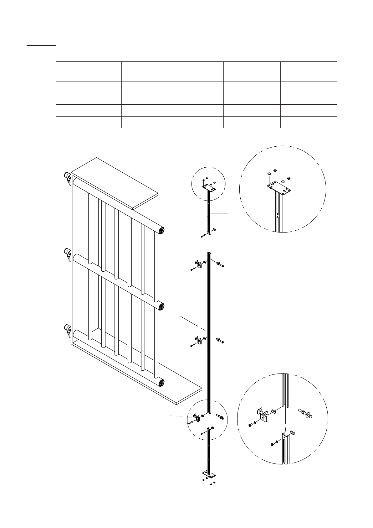
3.6 MultiPipe Support (accessory)
Range duct height
[mm]
Art.-No. Foothold (Pos. 1)
No. x Length [mm]
Rail (Pos. 2)
[mm]
Bracket (Pos. 3)
450...950 1117477 1 x 450 mm 500 4
950...1350 1117478 2 x 450 mm 500 4
1350...2300 1117479 2 x 450 mm 1400 4
2300...3200 1117480 2 x 450 mm 2300 4
1
1
2
3

13
4.1 Putting into operation
When connected to several basic units these should be operated in parallel.
Otherwise condensate runs into the units switched off and lls these until
overow occurs. Problems can then arise when switching on again.
The following should be ensured when putting into operation:
1. that the system pressure don’t increase over 1500 Pa. The system
pressure is componed of the airduct static pressure, the pressure drop
over the MultiPipe system (typical 500 Pa) and the back pressure in the
steam hose (typical 100 Pa/m)
2. that no water splashes from the steam distribution system and the con-
densate runs out of the system satisfactorily. Condensating formation
may be caused by:
• Steam supply pipe not properly drained
• Metallic steam pipe inadequately insulated
• Overstressed steam generator feeds water through steam pipe
• System condensate drain is block ed
• Extreme back-pressure in condensate hose
• Incorrect installation of conden sate hose
4.2 Operation
• Carry out visual checks periodically
• Further details according to the installation and operating instructions of
the humidier
4 Putting into operation and operation

14
Pos. Article Art.-/SAP-No.
1 Flange connection cpl. DV71 2546102
2 O-ring ø59.69 x ø5.34 (3 pcs) 2556745
3Sealing cap with xation 2556746
4 Sealing cap ø10 (3 pcs) 2559240
5 Hose clamp DS35 (2 pcs) 2539583
6 Internal sealing 2556747
7 Pipe clamp with O-ring 2556748
8 O-ring for pipe clamp (5 pcs) 2556749
--- Sealing cap ø41 2567040
5 Spare parts list
1
4
5
2
6
3
7
8

© Nordmann Engineering Ltd., Printed in Switzerland
Technical modifications reserved

NORDMANN
ENGINEERING
NORDMANN
ENGINEERING
Dampfluftbefeuchter econoVap
Reg.No. 40002-2
Manufacturer:
Nordmann Engineering Ltd.
www.nordmann-engineering.com, [email protected]
Table of contents


 operating instructions")


