IBC SL 26-260 G3 User manual

120-271F R2 |1
Note
IfconvertingfromPropanetoNaturalGas,ordertheNaturalGasConversionPartsKit(IBCPart#P-
301)fromyourauthorizedIBCDistributor.
UsethePropaneGasconversionpartskitifthefuelsourceatthesiteusesPropaneandthemodulatingboilerhas
beensetup(factoryfire-tested)tooperatewithNaturalGas.Checktheratingplateontheboilertoseewhichfuel
sourcetheparticularboilerhasbeensetupwith.
Usingthisconversionkit,aqualifiedtechnicianwillneedto:
1. Performafuelconversion.
2. Performacombustiontest.
3. Fillintheinformationrequiredonthefuelconversionlabels,andaffixthemtotheboileraftertheconversion
iscompleted.
Warning
Thisconversionkitshallbeinstalledbyaqualifiedserviceagencyinaccordancewiththe
manufacturer’sinstructionsandallapplicablecodesandrequirementsoftheauthorityhaving
jurisdiction.Iftheinformationintheseinstructionsisnotfollowedexactly,afire,anexplosionor
productionofcarbonmonoxidemayresultcausingpropertydamage,personalinjuryorlossoflife.
Thequalifiedserviceagencyisresponsiblefortheproperinstallationofthiskit.Theinstallationisnot
properandcompleteuntiltheoperationoftheconvertedapplianceischeckedasspecifiedinthe
manufacturer’sinstructionssuppliedwiththekit.
Theboilerwillautomaticallyde-ratethemaximuminputatarateofapproximately2%per1,000’above4,500’.The
gasvalveszerogovernorwillensurethatthegas:airmixtureisnotaffectedataltitude.
Includedwiththeconversionkit:
1xLPMixer,260G3-IBCPart#180-162 1xInstallerIdentifierLabel-IBCPart#080-244A
1xO-ring-IBCPart#150-073 3xScrewM4x12IBCPart#150-164
1xRatingPlateFuelOverlay-IBCPart#080-240 3xWasher,FlatIBCPart#150-099
1xGasValveConversionLabel-IBCPart#080-107 1xGasket,GasValveCouplerIBCPart#250-742C1
SL 26-260 G3 - Fuel Conversion to
Propane (NG-LP) P-300

Combustion Test Target Ranges
Figure1Gas valve and fan
TheLowFire(Zero-offset)valveadjustmentcaponthegasvalvehasbeenfactoryset.Donottamperwithoradjust
thisscrewinthefield.ContactthefactoryforwritteninstructionsifconsideringfieldadjustmentoftheLowFire(zero
offset)adjustment.
TheHighFire(Gas:Air)ratioadjustmentscrewisaslottedbrassscrewtotheleftofthelongbrassprotrusiononthe
frontofthegasvalve.Itwillhavetobeadjustedtoattainoptimumcombustionresultswheneverfuelconversionis
undertaken;however,nomixtureadjustmentshallbeperformedunlessdonebyaqualifiedtechnicianusingproperly
functioningandcalibratedcombustionanalyzingequipment.
Fuel High Fire Low Fire Co Max PPM
Range Target
Range Target
NaturalGas
9.0–10.0 9.5
8.2–9.2 8.7
<150
Propane
10.3–11.3 10.8
9.3–10.3 9.8
<250
Table 1 Combustion test target ranges - CO2 / Maximum CO
Note:LowFireCO2shouldbeatleast0.5%lowerthanHighFireCO2.
2|

SL 26-260 G3 - Conversion to propane (NG-LP) - P-Kit 300 |3
Fuel Conversion Instructions
Thefollowingproceduremustbecarriedoutbyaqualifiedtechnician.
Caution
Beforeyoudisconnecttheelectricalpower,youmustshutoffthegassupply.
To perform a fuel conversion:
1. Ensurethatthegassupplyisturnedoffatthegasshut-offvalve.
2. Undothebrasscouplingnutbetweenthegasvalveandtheventurimixingdevice.
3. Movethegasvalvetotheside.
4. Notetheorientationandthescrewpositionsoftheventurimixingdevice.
5. RemovetheventurimixingdevicefromthebaseofthefanbyunscrewingthePhillipsHeadscrews.
6. Installthenewfuel-appropriateventurimixingdeviceusingthePhillipsHeadscrews.
7. Checkthatthegasketisinplacebetweenthegasvalveandtheventurimixingdevice.
8. Connectthegasvalvetotheventurimixingdeviceusingthebrasscouplernutattachedtothegasvalve.
Now,carefullyfollowtheproceduresoncombustiontestingandthecorrectadjustment.
Combustion testing and adjustment
Danger
Acombustiontestchecksthatthegasvalveisoperatingproperlyinthefield.Toperforma
combustiontest,youmustbeaqualified,trainedandlicensedgasfitter.
MakingadjustmentstotheIBCgasvalvewithoutaproperlycalibratedgascombustionanalyzerand
bypeoplewhoarenottrainedandexperiencedinitsuseisforbidden.Failuretouseananalyzercan
resultinanimmediatehazard.
Model Number High Fire Input
SL26-260G3 260MBH
Table 2 Rated input of a converted boiler
Normalignitionsystemsequenceofoperation:
Theboilercontrol,uponacallforheatorDHW,turnsonthecombustionfanfora20-secondpre-purge,then
energizesthesparkelectrodeandgasvalvefora4-secondtrialforignition.

Iftheburnerdoesnotlight,theprocessisrepeateduntiltheburnerlightsandflameisdetected.After3trialsfor
ignition,theboilerlocksoutandwillneedtobemanuallyresetbyclearingtheerroronthetouchscreencontroller
(Diagnostics>AdvancedDiagnostics>ClearErrors).Theboilerautomaticallyresetsafter60minutes,ifnoaction
istaken.
To perform a combustion test and adjustment:
1. Turnofftheboiler’sgasshut-offvalve.
2. Withasmall(1/8"or3mm)flatscrewdriver,opentheinletgassupplypressuretestportbyturningitscenter-
screw1fullturncounterclockwise.
3. Attachamanometertotheinletpressuretestportandturnongastoappliance.
Staticmanometerreadingshouldbeideally7"w.c.forNaturalGasand11"w.c.forPropane.
Minimumandmaximumstaticpressureshouldbebetween5"and14"w.c.Monitorpressure
throughoutthecommissioning(start-up)procedure.Pressuremaydropupto1"to2"w.c.athighfire.
4. Beforeyouchangetheloadtomanualcontrol,notetheloadsetting.
5. Settheloadtomanualcontrol,andsettheheat-outvaluetothemaximumMBHfortheboiler.Thisload
shouldbelargeenoughtoallowtheboilertooperateathighfireforover10minutes.
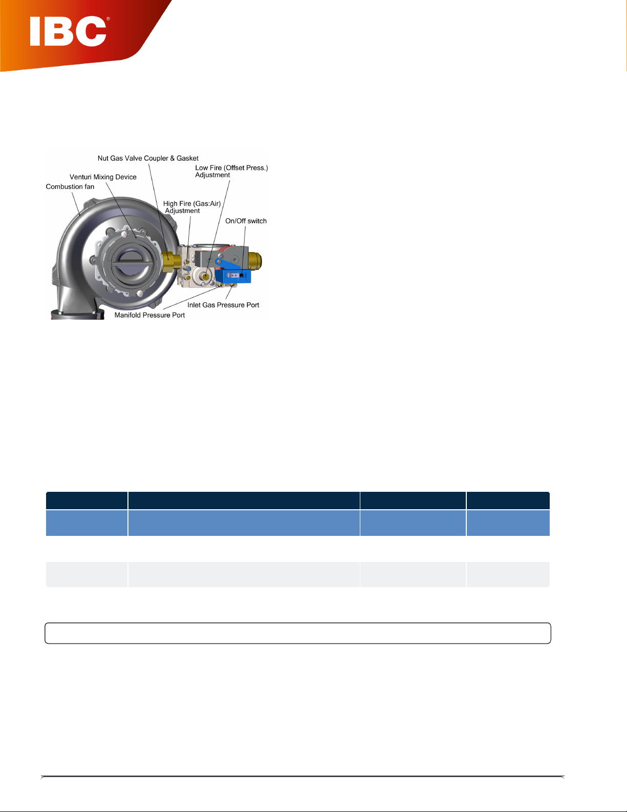
6. Withacombustionanalyzerprobeinthefluegastestport,checkthefluegasreadingandadjustthegas:air
ratioscrewtobringthefluegastowithintheparametersindicatedinTable 1 .
7. Adjustslowly(clockwise)theHighFire(Gas:AirRatioAdjustment)screwtoobtainthecorrectCO2value
(seeTable 1 ).Maketinyadjustments(mayrequireseveralturns).TurningtheHighFire(Gas:AirRatio
Adjustment)screwclockwisewillleanouttheflame.
Note
Clockthegasmeter(seeinstructionsonPage6)toconfirmfullmaximumratingplateinput.
CheckthemeasuredresultswithTable2.
8. Settheheat-outvalueinmanualmodetotheminimumMBHfortheboiler(seeTable 1 ).
9. WhiletheboilerisatLowFire,comparethecombustionreadingagainstthereadinginTable2.Thereading
shouldbewithintherangelisted.
10. Restoretheloadtothepreviousloadtype.Alltheprogrammedsettingswillberestoredandtheloadwill
operateasbefore.Confirmasmoothignitionsequence.
11. Turnoffthegassupplyatthegasshut-offvalve.
12. Disconnectthepowertotheboiler.
13. Disconnectthemanometer.
14. Closethegassupplytestportscrewbyturningclockwise.
15. Turnonthegassupplyshutoffvalveandtestforgasleaks.
16. Restorepowertotheboiler.
Nextyoumustfillintheinformationandaffixtheincludedfuelconversionlabelstotheboilerasindicatedafterthe
conversioniscompleted.
4|

SL 26-260 G3 - Conversion to propane (NG-LP) - P-Kit 300 |5
Completing and Affixing the Conversion Labels
1. Fillintheconversionlabels(includedinthekit)associatedwiththenewfueltype.
2. Placetheconversionlabelsontotheboileratthepositionsindicatedonthelastpage.
Clocking the Meter (Natural Gas)
1. Turnoffallotherappliancesandpilots.
2. Turnontheboilerandsettheboilertohighfire.
3. Ensuretheboilerhasalargeloadtoheat,sothattheboilerwillnotshutoff.
4. WithaStop-Watch,recordthenumberofsecondsforthesmallestdialtomake1fullrevolution.
5. CFH=(3600xDialSize)/Seconds.
6. CFHx1000(checklocalBtucontent)=InputBtu’s.
Note
For2PSImetersmultiplyCFHx1.097
ForMetricmetersmultiplyCFHx35.3
For2PSImetricmetersmultiplyCFHx1.097x35.3
ForAltitudeabove4,500’deduct2%per1,000’ofaltitudefromtheInputBtu’s.

Where to Place Conversion Labels on the Boiler
6|
Table of contents
Other IBC Industrial Equipment manuals