Nordson ASYMTEK Spectrum Series User manual

Spectrum
®
Series
Single-Axis Automatic
Tilt Mechanism
Owner’s Manual

P/N 7254855, Revision A Original Instructions ©2014
Notice
This is a Nordson ASYMTEK publication which is protected by copyright. Original copyright date 2014.
No part of this document may be photocopied, reproduced, or translated to another language without the
prior written consent of Nordson ASYMTEK. The information contained in this publication is subject to
change without notice.
Manuals on the Internet
For the convenience of Nordson ASYMTEK customers and field service representatives, copies of
Nordson ASYMTEK manuals can be downloaded from:
http://www.nordsonasymtek.com
Contact Us
Nordson ASYMTEK welcomes requests for information, comments, and inquiries about its products.
Please contact us using the information below:
Headquarters 2762 Loker Avenue West
Carlsbad, CA 92010-6603
USA
Toll Free:
1-800-ASYMTEK (1-800-279-6835)
Tel:
+1-760-431-1919
Fax:
+1-760-431-2678
E-mail:
info@nordsonasymtek.com
Website:
www.nordsonasymtek.com
Technical Support
USA:
1-800-ASYMTEK (1-800-279-6835)
Other regions: www.nordsonasymtek.com Tech Support
Trademarks
Asymtek®, DispenseJet®, NexJet® and Fluidmove®are registered trademarks of Nordson Corporation.
Spectrumis a trademark of Nordson Corporation.

Introduction i
Table of Contents
1Introduction ......................................................................................................................................... 1
1.1 Overview .................................................................................................................................. 1
1.2 System Requirements.............................................................................................................. 1
1.3 System Components................................................................................................................ 1
1.4 Supported Dispensing Valves .................................................................................................. 2
1.5 Theory of Operation ................................................................................................................. 3
2Safety ............................................................................................................................................... 5
2.1 Overview .................................................................................................................................. 5
2.2 Safety Warning Symbols.......................................................................................................... 5
2.1 Equipment Use......................................................................................................................... 5
2.1.1 Intended Use ............................................................................................................... 5
2.1.2 Misuse ......................................................................................................................... 5
2.2 Safety of Personnel.................................................................................................................. 6
2.3 Preventing Equipment and Workpiece Damage ...................................................................... 6
2.3 Material Safety ......................................................................................................................... 6
2.4 Disposal.................................................................................................................................... 6
3Installation and Setup......................................................................................................................... 7
3.1 Overview .................................................................................................................................. 7
3.2 Tilt Bracket Set Up ................................................................................................................... 7
3.2.1 Tilt Right and Left ........................................................................................................ 7
3.2.2 Tilt Front and Back ...................................................................................................... 8
3.3 Valve Connections ................................................................................................................... 9
3.4 Software Setup....................................................................................................................... 10
4Operation ........................................................................................................................................... 11
4.1 Overview ................................................................................................................................ 11
4.2 Safety First ............................................................................................................................. 11
4.3 Dot and Line Parameters for Tilt ............................................................................................ 12
4.3.1 Dot Parameters ......................................................................................................... 12
4.3.2 Line Parameters........................................................................................................ 13
4.4 Valve Offsets .......................................................................................................................... 14
4.4.1 Machine Offset Parameters ...................................................................................... 14
4.4.2 Running the Valve Offsets Procedure....................................................................... 16
4.5 Creating a Program with Tilt................................................................................................... 24
4.6 Running a Program ................................................................................................................ 25

ii Introduction
5Troubleshooting ................................................................................................................................ 27
5.1 Overview ................................................................................................................................ 27
5.2 Safety First ............................................................................................................................. 27
5.3 Record Keeping...................................................................................................................... 27
6Functional System Check ................................................................................................................ 29
6.1 Initialization Test..................................................................................................................... 29
6.2 I/O Test................................................................................................................................... 29

Introduction iii
Table of Figures
Figure 1-1 Two-Position Tilt Bracket (Front/Rear) .................................................................................. 1
Figure 1-2 Two-Position Tilt Bracket (Right/Left) .................................................................................... 1
Figure 1-3 Tilt Bulkhead .......................................................................................................................... 2
Figure 1-4 Mini Service Station Mounted on Rear Conveyor Rail .......................................................... 2
Figure 1-5 Tilt Angles .............................................................................................................................. 3
Figure 3-1 Tilt Bracket Mount (Right/Left)............................................................................................... 7
Figure 3-2 Tilt Bracket (Right/Left).......................................................................................................... 7
Figure 3-3 Home Position Adjustment (Right/Left) ................................................................................. 8
Figure 3-4 Travel Limit Adjustment (Right/Left) ...................................................................................... 8
Figure 3-5 Tilt Bracket Mount (Front/Back)............................................................................................. 8
Figure 3-6 Tilt Bracket (Front/Back)........................................................................................................ 8
Figure 3-7 Valve Connections (Right/Left Bracket)................................................................................. 9
Figure 3-8 Setup Valves........................................................................................................................ 10
Figure 4-1 Dot Parameters.................................................................................................................... 12
Figure 4-2 Line Parameters .................................................................................................................. 13
Figure 4-3 Machine Offset Parameters Setup ...................................................................................... 14
Figure 4-4 Fiducial Assisted Setup Windows........................................................................................ 15
Figure 4-5 Machine Setup Window....................................................................................................... 16
Figure 4-6 Valve Offsets: Safe Z Height ............................................................................................... 17
Figure 4-7 Teaching Needle-to-Camera XY Offset............................................................................... 18
Figure 4-8 Camera to Height Sense Probe or Laser XY Offset............................................................ 19
Figure 4-9 Needle to Height Sensor Z Offset........................................................................................ 20
Figure 4-10 Needle to Height Sensor Z Offset Summary ....................................................................... 20
Figure 4-11 Valve 1 Purge Location ....................................................................................................... 21
Figure 4-12 Valve 1 Scale Location ........................................................................................................ 22
Figure 4-13 Alignment Dot 1 Dispensing Valve 1 ................................................................................... 23
Figure 4-14 Programming Window ......................................................................................................... 24
Figure 4-15 Create Workpiece ................................................................................................................ 24
Figure 4-16 Set Tilt Instruction ................................................................................................................ 25
Figure 4-17 Run Production .................................................................................................................... 26
Figure 6-1 I/O Test Dialog..................................................................................................................... 29
Table of Tables
Table 2-1 Safety Warning Symbols ....................................................................................................... 5
Table 4-1 Manual Run Commands...................................................................................................... 26
Table 5-1 Troubleshooting ................................................................................................................... 27
Table 6-1 Tilt Direction I/O ................................................................................................................... 29


Introduction 1
1 Introduction
1.1 Overview
The Single-Axis Automatic Tilt Mechanism is designed for use with Nordson ASYMTEK’s S-9XX or
S2-9XX Series Dispensing Systems configured with DJ or DV Series Valves. This feature tilts the valve to
allow for easier dispensing on the side of components.
This manual describes the software setup, hardware setup, and operation of the tilt mechanism. Refer to
the applicable valve manual for detailed instructions on valve operation.
1.2 System Requirements
Dispensing System:
Spectrum S-9XX or S2-9XX Series Dispensing Systems
Dispensing Valve: Any DispenseJet (DJ-series) or DV-series valves. For other valve
types, contact Nordson ASYMTEK.
Software:
Fluidmove
Fluidmove Version:
Version 6.0 or higher
WARNING! CAUTION!
DO NOT operate the dispensing system unless you have been trained to do so.
Operating the dispensing system without proper training may result in personal
injury or dispensing system damage.
1.3 System Components
The Single-Axis Automatic Tilt Mechanism consists of the following components:
•Tilt Bracket
•Tilt Bulkhead
•Mini Service Station Mounted on Front Conveyor Rail
Figure 1-1 Two-Position Tilt Bracket
(Front/Rear)
Figure 1-2 Two-Position Tilt Bracket
(Right/Left)

2 Introduction
Figure 1-3 Tilt Bulkhead
Figure 1-4 Mini Service Station Mounted on Rear Conveyor Rail
1.4 Supported Dispensing Valves
The following Nordson ASYMTEK valves are supported for use with the tilt feature:
•DJ-9500
•DJ-2100 (with 90 degree dovetail adapter bracket)
•DV-7000 and DV-8000
•Legacy DV valves
The following Nordson ASYMTEK valves are not supported:
•DP-3000
•NexJet
•DJ-100
•SV-100

Introduction 3
1.5 Theory of Operation
The Single-Axis Automatic Tilt Mechanism can tilt the dispensing valve in one of the following positions:
•Vertical
•Counterclockwise (CCW)
•Clockwise (CW)
The tilt angle can be adjusted 10, 20 or 30 degrees.
The tilt bracket can be mounted in two ways:
•Front and rear tilt
•Right and left tilt
The tilt bracket is driven by a three position air cylinder, where the top port controls whether a center stop
is enabled or not. In order for the cylinder to reach the center position, the top and bottom ports must be
energized at the same time. To create the proper center holding force, the air pressure on the top port
must be about twice as much as the pressure on the bottom port. To create this pressure difference,
there is a small regulator mounted on the left side of the bulkhead. This regulator should be set to 40 psi.
The angle of tilt is determined by where the stops are located. After the tilt system has been set up, the
user is able to select a tilt direction in the Fluidmove software. After setting a tilt angle instruction in
Fluidmove, all subsequent instructions are performed at the specified tilt until a new tilt instruction is
added. See 4.5 Creating a Program with Tilt.
Figure 1-5 Tilt Angles


Safety 5
2 Safety
2.1 Overview
Dispensing system operation involves heat, air pressure, fluid pressure, mechanical and pneumatic
devices, electrical power, and the use of hazardous materials. Refer to the safety section of your
particular dispensing system and valve manuals prior to installing and operating the Single-Axis Tilt
Mechanism.
Safety is considered a joint responsibility between the original equipment manufacturer (Nordson
ASYMTEK) and the end-user (owner). All safety precautions and practices should be in accordance with
local regulations and facility practice.
2.2 Safety Warning Symbols
The following warning symbols are located throughout the manual to warn of personal or property
damage.
Table 2-1 Safety Warning Symbols
Symbol Description
Personnel Safety Warning. This symbol appears in a
shaded text block to warn you about actions that could cause
personal injury or death.
Property Damage Caution. This symbol appears in a shaded
text block to warn you about actions that could cause serious
damage to the machinery, software, parts being processed,
and facilities.
2.3 Equipment Use
2.3.1 Intended Use
Use of Nordson ASYMTEK equipment in ways other than those described in the documentation supplied
with the equipment may result in injury to persons or damage to property.
2.3.2 Misuse
Some examples of unintended use of equipment include:
Using incompatible materials
Making unauthorized modifications
Removing or bypassing safety guards or interlocks
Using incompatible or damaged parts
Using unapproved auxiliary equipment
Operating equipment in excess of maximum ratings
WARNING! Unsafe equipment conditions can result in personal injury or property damage.
Failure to adhere to safety warnings and precautions can result in serious bodily
harm to the user.

6 Safety
2.4 Safety of Personnel
•Only trained personnel should be permitted to perform installation, operation, maintenance,
and troubleshooting procedures.
•Immediately push the red Emergency Machine Off (EMO) button on your dispensing system
if personnel are in danger.
•Do not touch the moving parts while the dispensing system is operating.
•Follow Material Safety Data Sheet (MSDS) recommendations for the proper handling of
hazardous materials.
•Make sure all facility power sources are safely grounded.
•Routinely inspect all air hoses and electrical cables for damage.
•Relieve pneumatic pressure before adjusting or servicing pressurized components.
2.5 Preventing Equipment and Workpiece Damage
•Immediately push the EMO button on the dispensing system if the dispensing system,
valve, or a workpiece is in danger of being damaged.
•Use standard Electrostatic Discharge (ESD) precautions when working near sensitive
components. Always wear a grounding strap and connect it to the ESD ground before
handling workpieces and equipment.
•Perform all recommended maintenance procedures at the suggested intervals.
•Immediately contain and clean up any caustic or conductive fluid spills as recommended in
the material manufacturer’s MSDS.
•Use only replacement parts that are designed for use with the original equipment.
2.6 Material Safety
•Follow Material Safety Data Sheet (MSDS) recommendations for the proper handling,
cleanup, and disposal of all materials and fluids and their containers (i.e., syringes, cups,
reservoirs, etc.) used with the dispensing system.
•Know the MSDS recommendations for treatment of injury resulting from exposure to
hazardous materials.
•Always wear appropriate personal protective equipment (PPE) as recommended by facility
safety practices and the material manufacturer’s MSDS.
•When working with multiple fluids, refer to the MSDS to ensure the materials are
compatible.
•If possible, save or recycle unused materials. Refer to the MSDS before saving or recycling
unused materials.
2.7 Disposal
Dispose of equipment and materials used in operation and servicing in accordance with local
regulations.

Installation and Setup 7
3 Installation and Setup
3.1 Overview
In order to use the tilt feature, the tilt bracket must be setup properly.
This section covers the following topics:
•Tilt Bracket Set Up
•Valve Connections
•Software Setup
3.2 Tilt Bracket Set Up
The tilt bracket can be set up in two ways and may be configured with or without sensors on the air
cylinder.
3.2.1 Tilt Right and Left
To set up the right and left tilt bracket:
1. If using a DV 7/8000 valve, install a mount spacer (P/N 7257077) on the Z-plate with four
(4) M4 socket head screws (P/N 49-4312) and a 3mm hex wrench (not shown). The spacer
would be installed in the same place as the mount shown in Figure 3-1.
2. Install the mount 7256201 with four (4) M4 socket head screws (P/N 49-4312) and a 3mm
hex wrench. See Figure 3-1.
3. Install the tilt mechanism using a 4 mm Hex wrench. See Figure 3-2.
4. Connect pneumatic lines as shown in Figure 3-2.
Figure 3-1 Tilt Bracket Mount (Right/Left)
Figure 3-2 Tilt Bracket (Right/Left)

8 Installation and Setup
Figure 3-3 Home Position Adjustment (Right/Left)
Figure 3-4 Travel Limit Adjustment (Right/Left)
5. Adjust the horizontal position of the tilt bracket using a 4 mm hex wrench to allow the
machine to home when the valve is tilted CCW as shown in Figure 3-3.
6. Adjust the X travel limit to avoid collision when the valve is tilted CW as shown in Figure 3-4.
3.2.2 Tilt Front and Back
To set up the front and back tilt bracket:
1. Install the mount with four (4) M4 socket head screws (P/N 49-4312) and a 3mm hex
wrench. See Figure 3-5.
2. If using a DV valve, install the mount in the right set of holes so that the DV does not collide
with the machine during rotation.
3. Install the tilt mechanism using a 4 mm hex wrench. See Figure 3-6.
4. Connect pneumatic lines as shown in Figure 3-6.
Figure 3-5 Tilt Bracket Mount (Front/Back)
Figure 3-6 Tilt Bracket (Front/Back)

Installation and Setup 9
3.3 Valve Connections
To connect the valve hoses:
Connect the valve hoses for each valve to the dispensing system bulkhead as follows:
•Black Hose – Valve Off
•Clear Hose – Fluid Pressure
•Green Hose – Cool 1 (Active Air)
Figure 3-7 Valve Connections (Right/Left Bracket)

10 Installation and Setup
3.4 Software Setup
The Single-Axis Automatic Tilt Mechanism works in conjunction with the Fluidmove software, version 6.0
or higher. If necessary, install Fluidmove 6.0 according to the Readme file instructions included with the
software.
WARNING! CAUTION!
Refer to the safety section in the applicable dispensing system manual prior to
operating the dispensing system. Failure to comply with any of the safety
recommendations could cause serious injury to the user or damage to the
dispensing system.
To configure the Fluidmove software:
1. Power on the dispensing system.
Refer to the applicable dispensing system manual if necessary.
2. Start Fluidmove.
Refer to the Fluidmove User Guide if necessary.
3. In the Fluidmove Main Window, select Configuration > Setup Valves.
The Setup Valves window (Figure 3-8) opens.
Figure 3-8 Setup Valves
4. Make sure the following options are enabled. A check mark indicates they are enabled. See
Figure 3-8.
•Tilt Bracket Installed
•Enable Valve Tilt
•Bracket Type (Left/Right or Front/Rear)
•Tilt Sensors, if applicable
5. Select the appropriate valve type and click on OK.

Operation 11
4 Operation
4.1 Overview
Before operating the valve tilt feature, you must define the Dot and Line Parameters in Fluidmove, run a
Valve Offsets procedure, and create a program with tilt commands.
NOTE Refer to the Fluidmove User Guide for detailed information on Fluidmove programming
and fluid setup.
This section covers the following topics:
•Dot and Line Parameters for Tilt
•Valve Offsets
•Creating a Program with Tilt
4.2 Safety First
Operation of your dispensing system involves heat, air pressure, electrical power, heat, mechanical
devices, and the use of hazardous materials. It is essential that every person servicing or operating the
dispensing system fully understands all hazards, risks, and safety precautions. Refer to the safety section
in the applicable dispensing system manual for important safety information.

12 Operation
4.3 Dot and Line Parameters for Tilt
Prior to running valve offsets and creating a program, you must define dot and line parameters. Dot and
line parameters control the size and accuracy of dot or line dispensing.
4.3.1 Dot Parameters
To edit dot parameters:
1. In the Fluidmove Main Window, select Teach a Program.
The Programming Window opens.
2. Select Edit > Dot Parameters from the drop-down menu.
The Dot Parameters window opens.
3. Select the Valve Tilt tab (Figure 4-1).
4. Select the tilt direction for each dot that will be used in the program.
The dispense gaps for lines and dots are set in the Dot Parameters. See 4.3.2 Line
Parameters.
5. Select None in the Use Offset to Disp Gaps pull down window.
None will force the user to run an offset for each dispense gap.
If Dot Type 1 is selected, the offsets created by Dot Type 1 will be used for all dot types.
This can result in dispense inaccuracies due to the different dispense gaps. If Dot Type 2
is selected, the offsets created by Dot Type 2 will be used for all dot types, etc.
6. Click on Apply and then on OK to close the window.
7. Click on to return to the Fluidmove Main Menu.
Figure 4-1 Dot Parameters

Operation 13
4.3.2 Line Parameters
NOTE The dispense gaps for both lines and dots are set in the Dot Parameters window. The
line dispense gaps are the same as the dot dispense gaps of the same number. The
Valve Tilt tab is only available in the Dot Parameters window (Figure 4-1).
To edit line parameters:
1. In the Fluidmove Main Window, select Teach a Program.
The Programming Window opens.
2. Select Edit > Line Parameters from the drop-down menu.
The Line Parameters window opens (Figure 4-2).
Figure 4-2 Line Parameters
3. Notice that the Dispense Gap column is grayed out. The values correspond with those set
in the Dot Parameters window.
The Dispense Gap for Line Type 1 equals the Dispense Gap for Dot Type 1; the
Dispense Gap for Line Type 2 equals the Dispense Gap for Dot Type 2, etc.
4. Click on OK to close the window.

14 Operation
4.4 Valve Offsets
Because the dispensing valves can be set to different tilt directions and dispense gaps, a valve offset
routine must be performed. Valve offsets must be run in full to properly set up valves.
4.4.1 Machine Offset Parameters
To configure machine offset parameters:
1. In the Main Window, click on Configuration > Machine Offsets > Machine Offsets
Parameters.
The Machine Offset Parameters window (Figure 4-3) opens.
2. Make sure Scripted Valve Offsets is selected.
Figure 4-3 Machine Offset Parameters Setup
3. In the Machine Offsets Parameters section, make sure “_MachineOffsets.pss” is the
selected script file.
If not, click on Select Script File and select it from the list.
4. Select camera assisted script and click on Setup Fiducials.
The Machine Fiducial Setup Screen opens (Figure 4-4).
5. Click on the check box next to the device(s) to be located by fiducials during the setup
procedure.
The Setup button(s) for the selected device(s) becomes active.
This manual suits for next models
2
Table of contents
Other Nordson ASYMTEK Dispenser manuals
Popular Dispenser manuals by other brands
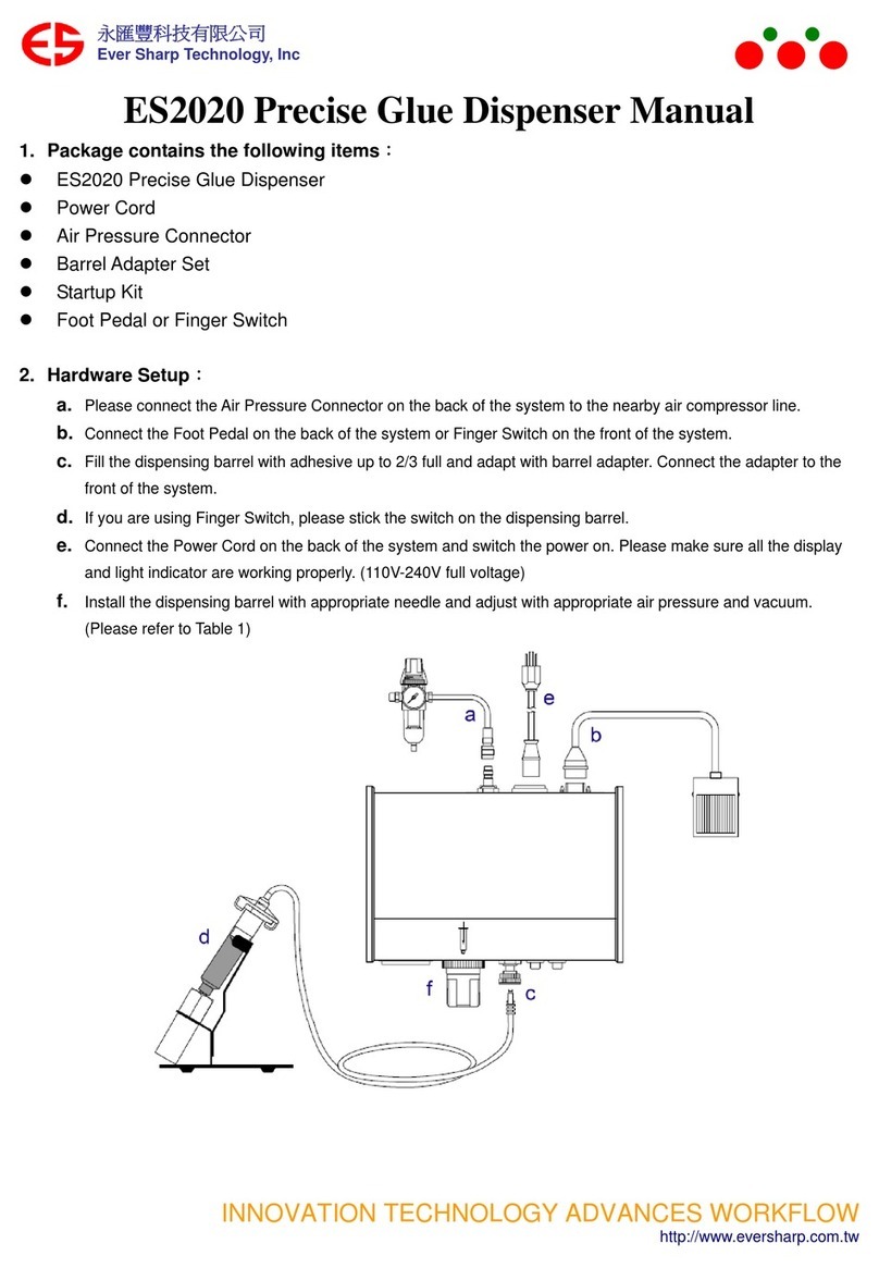
Ever Sharp Technology
Ever Sharp Technology ES2020 manual

Server
Server SlimLine DFD quick start guide

Cornelius
Cornelius NITROPRO MINI Service and Preventative Maintenance Manual
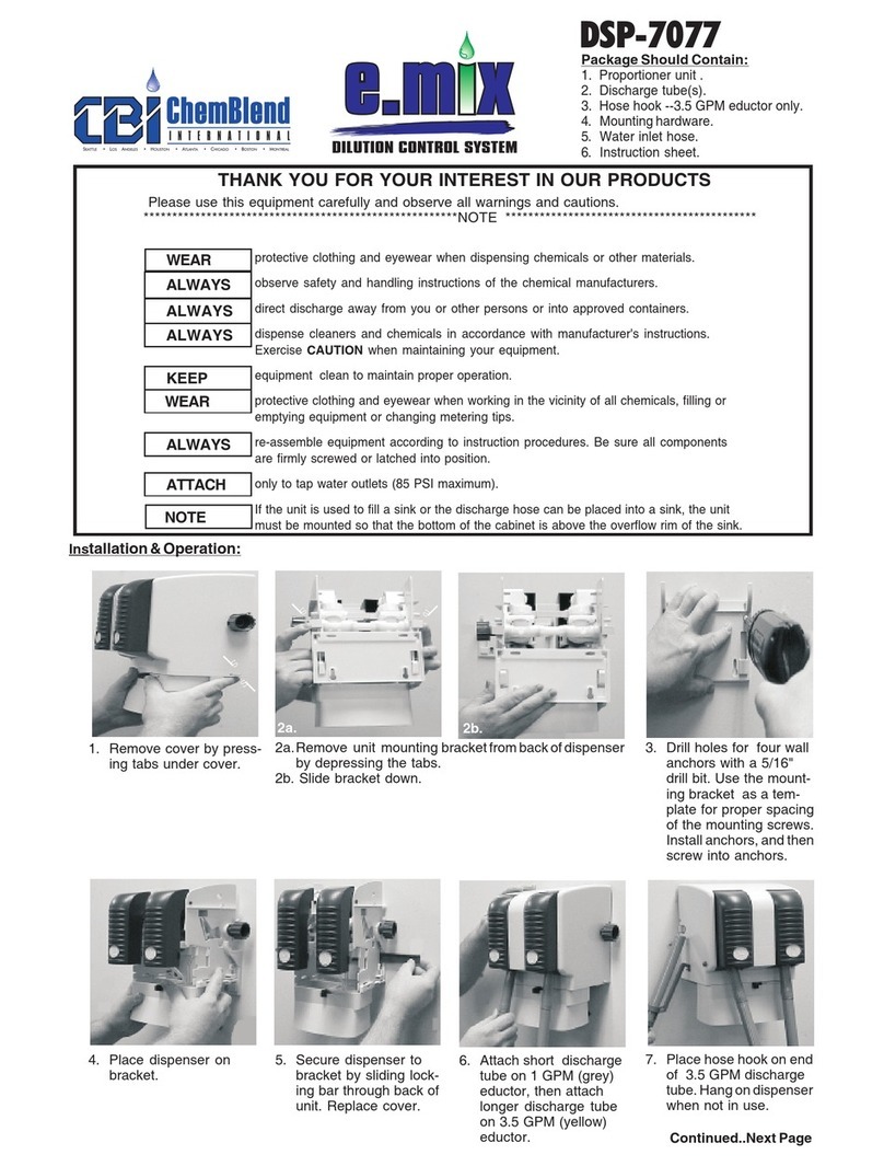
Nyco
Nyco e.Mix DSP-7077 Installation & operation
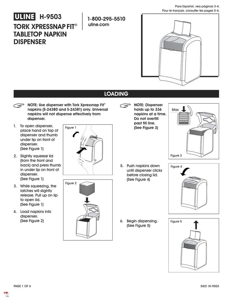
U-Line
U-Line TORK XPRESSNAP FIT H-9503 quick start guide

BOWMAN
BOWMAN BD211-0012 manual
