Nordson ASYMTEK DispenseJet Series User manual

DispenseJet
Series
DJ-9500
Owner’s Manual

P/N 7218010, Revision D ©2010
NOTICE
This is an Asymtek publication, which is protected by copyright. Original copyright date 2008. No part of this
document may be photocopied, reproduced, or translated to another language without the prior written consent of
Asymtek. The information contained in this publication is subject to change without notice.
Manuals on the Internet
For the convenience of Asymtek customers and field service representatives, copies of Asymtek manuals can be
downloaded from:
http://www.asymtek.com/support/tech_manuals.htm
Contact Us
Asymtek welcomes requests for information, comments, and inquiries about its products. Please contact us using the
information below:
Headquarters 2762 Loker Avenue West
Carlsbad, CA 92010-6603
USA
Toll Free: 1-800-ASYMTEK (1-800-279-6835)
Tel: +1-760-431-1919
Fax: +1-760-431-2678
Website: www.asymtek.com
Technical Support
USA: 1-800-ASYMTEK (1-800-279-6835)
Other regions:
www.asymtek.com Tech Support
Trademarks
Asymtek®, DispenseJet®, Millennium®, Century®, and Fluidmove®are registered trademarks of Asymtek.
Axiomis a trademark of Asymtek.
Microsoft®, Windows®, and Windows NT ®are registered trademarks of Microsoft Corporation.
All other brand or product names are trademarks or registered trademarks of their respective organizations.

Table of Contents i
Table of Contents
1Introduction ......................................................................................................................................... 1
Overview................................................................................................................................................ 1
Specifications ........................................................................................................................................ 4
2Safety.................................................................................................................................................... 5
Overview................................................................................................................................................ 5
Safety Warning Symbols ....................................................................................................................... 5
Safety of Personnel ............................................................................................................................... 5
Preventing Equipment and Workpiece Damage ................................................................................... 6
Material Safety ...................................................................................................................................... 6
3Theory of Operation ............................................................................................................................ 7
Overview................................................................................................................................................ 7
Adjustable Features .............................................................................................................................. 7
Fluid Pressure .......................................................................................................................... 7
Stroke Adjustment .................................................................................................................... 7
Solenoid Valve ......................................................................................................................... 7
Seat, Nozzle and Needle Assembly......................................................................................... 7
Active Nozzle............................................................................................................................ 7
Thermal Control Assembly....................................................................................................... 7
Dot and Line Parameters ......................................................................................................... 7
Body Heater ............................................................................................................................. 8
4Installation ........................................................................................................................................... 9
Overview................................................................................................................................................ 9
Safety First ............................................................................................................................................ 9
Unpacking the DJ-9500......................................................................................................................... 9
Installing the DJ-9500 Valve.................................................................................................................. 9
5Setup................................................................................................................................................... 13
Overview.............................................................................................................................................. 13
Setting Up the DJ-9500 ....................................................................................................................... 13
6Maintenance and Service ................................................................................................................. 17
Overview.............................................................................................................................................. 17
Disassembling the DJ-9500 – Wetted Parts ....................................................................................... 17
Cleaning and Inspecting the DJ-9500 – Wetted Parts ........................................................................ 19
Removing the Cup Seal ......................................................................................................... 19
Cleaning the Cup Seal ........................................................................................................... 19
Cleaning the Static Seal ......................................................................................................... 20
Removing the Static Seal ....................................................................................................... 20
Cleaning the Nozzle ............................................................................................................... 21
Assembling the DJ-9500 – Wetted Parts ............................................................................................ 23
Removing and Replacing the Needle Assembly................................................................................. 27
Lubricating the Retainer Assembly and Stroke Adjustment Assembly ............................................... 29
Removing and Replacing the Solenoid Valve or Thermal Control Assembly (TCA) .......................... 30

ii Table of Contents
7Troubleshooting ................................................................................................................................ 35
Overview.............................................................................................................................................. 35
Troubleshooting the DJ-9500 .............................................................................................................. 35
8Additional Information ...................................................................................................................... 39
Recommended Facility Items.............................................................................................................. 39
Return Material Authorization.............................................................................................................. 39
Input/Output Connection ..................................................................................................................... 40
Needle Assembly, Nozzle, and Seat Configuration ............................................................................ 41
Spares and Accessories...................................................................................................................... 44
Sample Application Settings ............................................................................................................... 46
9Illustrated Parts List.......................................................................................................................... 49

Table of Contents iii
Table of Figures
Figure 1-1 DispenseJet Series DJ-9500 (30cc Fluid Tube w/o Heat Exchanger)................................ 1
Figure 1-2 DispenseJet Series DJ-9520 (30cc Fluid Reservoir w/ Heat Exchanger) .......................... 2
Figure 1-3 DispenseJet Series DJ-9520 (6oz Fluid Tube w/ Heat Exchanger) ................................... 3
Figure 3-1 DJ-9500 Exploded View...................................................................................................... 8
Figure 4-1 Connection Diagram – Axiom X-1000............................................................................... 11
Figure 4-2 Connection Diagram – Spectrum S-900 Series................................................................ 12
Figure 5-1 Connecting the Fluid Reservoir (30cc Fluid Tube w/o Heat Exchanger).......................... 14
Figure 5-2 Connecting the Fluid Reservoir (30cc Fluid Reservoir w/ Heat Exchanger)..................... 15
Figure 5-3 Connecting the Fluid Reservoir (6oz Fluid Reservoir w/ Heat Exchanger) ...................... 16
Figure 6-1 Disassembling Wetted Parts (DJ9520 w/Cup Seal and Unitized Nozzle shown)............ 18
Figure 6-2 Removing the Seat............................................................................................................ 19
Figure 6-3 Removing the Fluid Seal ................................................................................................... 19
Figure 6-4 Cleaning the Static Seal.................................................................................................... 20
Figure 6-5 Removing the Static Seal.................................................................................................. 20
Figure 6-6 Nozzle, Seat, and O-ring Removal (Active Nozzle Pictured)............................................ 21
Figure 6-7 Inserting the Cup Seal ...................................................................................................... 23
Figure 6-8 Seal Fully Inserted ............................................................................................................ 23
Figure 6-9 Assemble the Static Seal .................................................................................................. 23
Figure 6-10 Place Static Seal on Needle ............................................................................................. 23
Figure 6-11 Seating the Static Seal...................................................................................................... 23
Figure 6-12 Stroke Adjustment Assembly Fully Opened ..................................................................... 24
Figure 6-13 Inserting the Seat .............................................................................................................. 24
Figure 6-14 Nozzle In Cavity Recess ................................................................................................... 24
Figure 6-15 TCA Placed Over Nozzle .................................................................................................. 24
Figure 6-16 Unitized Nozzle In Fluid Chamber Cavity Recess ............................................................ 25
Figure 6-17 Fluid Chamber/Unitized Nozzle Placed over Needle Assembly ....................................... 25
Figure 6-18 TCA Placed Over Unitized Nozzle .................................................................................... 25
Figure 6-19 Tightening the Collar ......................................................................................................... 25
Figure 6-20 Stroke Adjustment............................................................................................................. 26
Figure 6-21 Unscrewing the Needle Assembly .................................................................................... 27
Figure 6-22 Inserting the Needle Flange.............................................................................................. 27
Figure 6-23 Inserting the Needle .......................................................................................................... 28
Figure 6-24 Detaching the Needle from the Insertion Tool Base ......................................................... 28
Figure 6-25 Needle and Flange Fully Seated....................................................................................... 29
Figure 6-26 Loosening the Four Socket Head Screws (DJ-9500) ....................................................... 30
Figure 6-27 Loosening the Four Socket Head Screws (DJ-9520) ....................................................... 31
Figure 6-28 Pushing the Coolant Line through the Junction Box......................................................... 32
Figure 6-29 Removing the TCA Assembly ........................................................................................... 32
Figure 6-30 Attaching the TCA Assembly ............................................................................................ 32
Figure 6-31 Pulling the Coolant Line Back through the Junction Box .................................................. 32
Figure 6-32 Pressing the TCA into the Junction Box .......................................................................... 33
Figure 6-33 TCA Electrical Connectors ................................................................................................ 33
Figure 6-34 Connecting the Solenoid ................................................................................................... 33
Figure 6-35 Junction Box to Valve Body Alignment ............................................................................. 34
Figure 9-1 DJ-9500 Illustrated Parts List (Cup Seal, Standard Nozzle, and 30cc Mount) ................ 51
Figure 9-2 DJ-9520 Illustrated Parts List (Cup Seal, Unitized Nozzle, and 30cc Mount).................. 52
Figure 9-3 DJ-9520 Illustrated Parts List (Static Seal, Active Nozzle, and 6oz Mount) .................... 53

iv Table of Contents
Table of Tables
Table 6-1 Nozzle Cleaning Tools ...................................................................................................... 22
Table 7-1 DJ-9500 Troubleshooting – Symptom Based ................................................................... 35
Table 7-2 DJ-9500 Troubleshooting – Set-up Based........................................................................ 37
Table 7-3 DJ-9500 Troubleshooting – Component Based................................................................ 38
Table 8-1 Available Needle/Nozzle and Seat Sizes.......................................................................... 41
Table 8-2 DJ-9500 Spares and Accessories..................................................................................... 44
Table 8-3 DJ-9520 Spares and Accessories..................................................................................... 45
Table 8-4 Hardware Settings............................................................................................................. 46
Table 8-5 Software Settings .............................................................................................................. 46
Table 9-1 Illustrated Parts List........................................................................................................... 49

Introduction 1
1 Introduction
Overview
The DispenseJet Series DJ-9500 (Figure 1-1) is a non-contact dispenser providing high-speed delivery
and exceptional volumetric control for various fluids, including silicones, underfill, encapsulants, UV
adhesives, and silver epoxy. The DJ-9500 jets in tight spaces as small as 175 micrometers and creates
fillet wet-out widths as small as 300 micrometers on the dispensed side of the die. It dispenses fluid either
as discrete dots or as a rapid succession of dots to form a 100-micrometer diameter stream of fluid from
the nozzle. It is fully compatible with Asymtek DispenseMate, Axiom X-1000, Spectrum S-820, and
Spectrum S-900 Series Dispensing Systems.
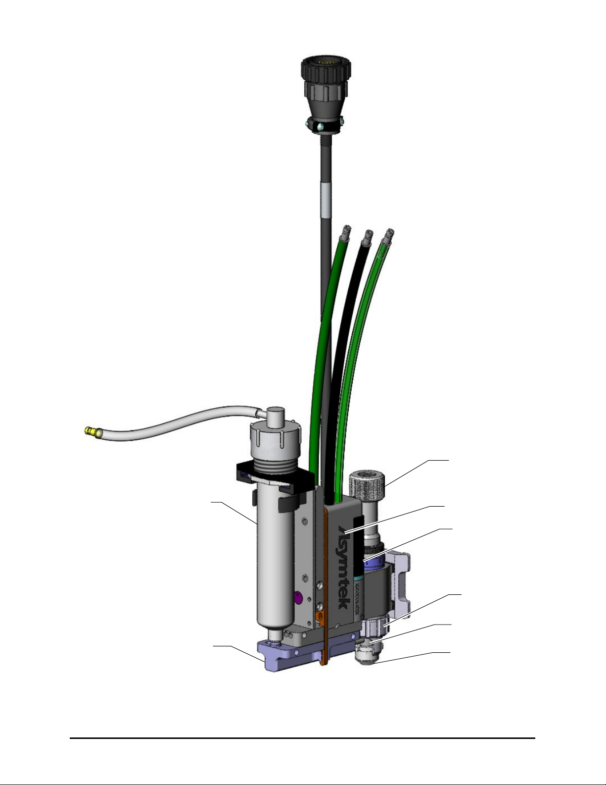
Figure 1-1 DispenseJet Series DJ-9500 (30cc Fluid Tube w/o Heat Exchanger)
Thermal Control
Assembly
Feed Tube
Assembly
Fluid Reservoir
Fluid Chamber
Stroke Adjustment
Knob
Collar (Retainer
Assembly)
Junction Box
Solenoid
2 Introduction
Figure 1-2 DispenseJet Series DJ-9520 (30cc Fluid Reservoir w/ Heat Exchanger)
Thermal Control
Assembly
Heat Exchanger
Fluid Reservoir
Fluid Chamber
Stroke Adjustment
Knob
Collar (Retainer
Assembly)
Junction Box
Solenoid

Introduction 3
Figure 1-3 DispenseJet Series DJ-9520 (6oz Fluid Tube w/ Heat Exchanger)
Thermal Control
Assembly
Fluid Reservoir
Fluid Chamber
Stroke Adjustment
Knob
Collar (Retainer
Assembly)
Junction Box
Heat Exchanger
Solenoid

4 Introduction
Specifications
Characteristic Specification
Size Width: 33 mm
Height: 142 mm
Depth: 100 mm (135mm w/ Body Heater)
Seat and Nozzle Carbide / Stainless Steel
Needle Assembly Carbide
Fluid Seal PEEK or Flouroloy
Fluid Chamber O-Ring Ethylene Propylene or Viton
Jet Body 6061-T6 Aluminum/Nickel Plated
NPE 303 Stainless Steel
Needle Assembly Bearings PEEK
Thermal Control Body 6061-T6 Aluminum
Nickel Plated
Feed Tube Assembly Fitting Female Luer per ANSI/HIMA MD70.1-1983
Maximum Cycle Frequency 200 Hz.
Minimum Valve Air Pressure 5.5 bar (80 psi)
Solenoid 24 VDC, 5 watts
Nozzle Heater (TCA) 24 VDC, 14.7 Watts, 40 ohms
Thermal Control RTD 100 ohm, platinum
Maximum Heater Set Point 100 °C
Body Heater Ch2 24 VDC, 50 Watts, 11.5 ohms
Body Heater Rtd 100 ohm, platinum
Max Heater Set Point 100 °C
*At Maximum Cycle Rate
NOTE Asymtek manufactures each DJ-9500 under strict manufacturing quality control
standards to ensure precise and reliable performance. To obtain maximum performance,
please read instructions carefully. Please contact Asymtek for the suitability of the
DJ-9500 technology for other applications.
Safety 5
2 Safety
Overview
Dispensing system operation involves heat, air pressure, fluid pressure, mechanical and pneumatic
devices, electrical power, and the use of hazardous materials. Refer to the safety section of your particular
dispensing system Operations Manual prior to installing and operating your DispenseJet Series DJ-9500.
Safety is considered a joint responsibility between the original equipment manufacturer (Asymtek) and
the end-user (owner). All safety precautions and practices should be in accordance with local regulations
and facility practice.
Safety Warning Symbols
Symbol Description
Personnel Safety Warning. This symbol appears in a
shaded text block to warn you about actions that could cause
personal injury or death.
Property Damage Caution. This symbol appears in a shaded
text block to warn you about actions that could cause serious
damage to the machinery, software, parts being processed,
and facilities.
Safety of Personnel
WARNING! Unsafe equipment conditions can result in personal injury or property damage.
Failure to adhere to safety warnings and precautions could result in serious bodily
harm to the user.
•Only trained personnel should be permitted to perform installation, operation, maintenance, and
troubleshooting procedures on the DispenseJet Series DJ-9500.
•Before performing maintenance or service on the DJ-9500, position it at the front of the
dispensing chamber. This will provide easy access to components and limit exposure to
hazardous areas.
•Immediately push the red Emergency Machine Off (EMO) button on your dispensing system if
personnel are in danger.
•Do not touch the moving parts while the dispensing system is operating.
•Follow Material Safety Data Sheet (MSDS) recommendations for the proper handling of
hazardous materials.
•Remove the DJ-9500 completely from the dispensing system and allow the heated parts to cool
before cleaning or performing maintenance.
•Relieve pneumatic pressure before adjusting or servicing pressurized components.

6 Safety
Preventing Equipment and Workpiece Damage
•Immediately push the EMO button on the dispensing system if the dispensing system, DJ-9500,
or a workpiece is in danger of being damaged.
•Use standard Electrostatic Discharge (ESD) precautions when working near sensitive
components. Always wear a grounding strap and connect it to the ESD ground before handling
workpieces and equipment.
•Perform all recommended DJ-9500 maintenance procedures at the suggested intervals.
•Immediately contain and clean up any caustic or conductive fluid spills as recommended in the
material manufacturer’s MSDS.
•If fluid gets into internal portions of the DJ-9500, immediately contact Asymtek Technical
Support.
•Use only replacement parts that are designed for use with the original equipment. Table 9-1
contains an illustrated parts list.
CAUTION! The DispenseJet Series DJ-9500 is a precision instrument of inherently safe
design. The use of any dispensing fluid and the related choice of solvent for
cleaning, as well as all associated safety precautions is the responsibility of the
end-user. Consult with your fluid supplier for recommendations on Personal
Protective Equipment and safety practices.
Material Safety
•Follow Material Safety Data Sheet (MSDS) recommendations for the proper handling, cleanup,
and disposal of hazardous materials.
•Know the MSDS recommendations for treatment of injury resulting from exposure to hazardous
materials.
•When working with multiple fluids, refer to the MSDS to ensure the materials are compatible.
•Always wear appropriate Personal Protective Equipment (PPE) as recommended by facility
safety practices and the material manufacturer’s MSDS.

Theory of Operation 7
3 Theory of Operation
Overview
The DJ-9500 is a normally closed, air-actuated, spring-return mechanism, which uses momentum transfer
principles to expel precise volumes of material. Pressurized air is regulated by a high-speed solenoid to
retract the Needle Assembly from the seat. Fluid, fed into the fluid chamber, flows over the seat. When
the air is exhausted, the needle travels rapidly to the closed position, displacing fluid through the seat and
nozzle in the form of a droplet. Multiple droplets fired in succession can be used to form larger dispense
volumes and lines when combined with the motion of a dispenser robot.
Adjustable Features
The following features affect performance of the DJ-9500 and are typically adjusted to fit your application.
Fluid Pressure
Fluid Pressure should be set so that fluid fills to the seat, but should not be influential in pushing the fluid
through the seat and nozzle. In general, higher fluid pressure results in a larger volume of material jetted.
Stroke Adjustment
The Stroke Adjustment controls the travel distance of the Needle Assembly. Turn counterclockwise to
increase Needle Assembly travel, turn clockwise to decrease travel. An increase of travel distance will
often result in a larger volume of material jetted.
Solenoid Valve
The Solenoid Valve controls the valve operation. When energized, it allows air in the jet air chamber to
compress a spring and thereby raise the Needle Assembly. When de-energized, the air is released and the
spring forces the piston down so that the needle tip contacts the seat. The valve ON/OFF times can be
adjusted in the Fluidmove software.
Seat, Nozzle and Needle Assembly
Seat, Nozzle and Needle Assembly geometries are typically the main factors controlling volume. Size is
determined based on the application and fluid properties. Other parameters are adjusted in accordance
with seat, nozzle and needle assembly choices. Sizes are listed in Table 8-1.
Active Nozzle
The Active Nozzle controls fluid break-off and minimizes accumulation at the nozzle tip.
Thermal Control Assembly
Fluid temperature often influences fluid viscosity and flow characteristics. The DJ-9500 is equipped with
a Thermal Control Assembly that assures a constant fluid temperature.
Dot and Line Parameters
In addition to the DJ-9500 hardware configuration and settings, Dot and Line Parameters are set in the
Fluidmove software program to control the size and quality of dots and lines dispensed. For information
on dispense parameters, refer to the Fluidmove User Guide or Online Help.

8 Theory of Operation
Body Heater
The Body Heater helps hold the DJ-9500 series assembly at constant temperature to protect it against
transient temperature fluctuation in the machine. The Heat Exchanger version will supply a fluid at a
constant temperature.
Figure 3-1 DJ-9500 Exploded View
Jet Body
Nozzle
Stroke Adjustment
Knob Assembly
Needle Assembly
Reservoir Holder
Collar
Seal
Thermal Control
Assembly (TCA)
Seat
Feed Tube
Assembly
Retainer
Fluid Chamber
O-Ring
Solenoid Valve
Fluid Reservoir

Installation 9
4 Installation
Overview
The DJ-9500 is designed for use on Asymtek DispenseMate, Axiom X 1000, Spectrum S-820, and
Spectrum S-900 Series Dispensing Systems. This section includes installation instructions applicable for
each of these systems.
This section includes the following installation instructions:
•Unpacking the DJ-9500
•Installing the DJ-9500
Safety First
Dispensing system operation involves heat, air pressure, fluid pressure, mechanical and pneumatic
devices, electrical power, and the use of hazardous materials. Refer to the Safety section of your particular
dispensing system manual prior to installing and operating your DJ-9500 Valve.
Unpacking the DJ-9500
Every care has been taken when packaging your DJ-9500. However, we recommend that you look for
obvious damage and verify contents against the packing slip.
Retain the case for storage of the DJ-9500 and accessories. Retain shipping cartons for future use.
If an item needs to be returned to Asymtek, obtain a Return Material Authorization (RMA) number
from Asymtek.
Installing the DJ-9500 Valve
If your DJ-9500 valve was factory installed, you do not need to perform this procedure.
WARNING! The procedures in this section should be performed by trained personnel only.
Tools and Materials Needed:
•4 mm hex wrench
NOTE Prior to installation, use the software or dispensing system position controls to move the
dispensing head to the front center of the dispensing area. Remove any valve currently
installed on the dispensing head. If the valve bracket installed is incompatible with the
DJ-9500, remove it and the Height Sensor (if present). Refer to the installation/removal
procedures in the applicable valve manual if necessary.

10 Installation
To install the DJ-9500:
1. Mount the DJ-9500 on the dovetail bracket and tighten with the 4-mm hex wrench.
2. Make the electrical connections according to the appropriate machine configuration shown in
Figure 4-1 and Figure 4-2.
3. Connect the pneumatic hoses as shown in Figure 4-1 and Figure 4-2. You should hear a click
when the hose is inserted properly.
The black hose connects to valve air.
The transparent green hose is used for nozzle cooling in elevated temperature
environments. Refer to the Fluidmove User Guide for software control setup of the
nozzle cooler. You can download the manual from:
http://www.asymtek.com/support/tech_manuals.htm
The green hose (if installed) is used for valve body cooling in elevated temperature
environments.
NOTE Verify that the cables and connections are secured adequately to account for the motion
of the robot.

Installation 11
Figure 4-1 Connection Diagram – Axiom X-1000


Setup 13
5 Setup
Overview
This section describes the procedures required to setup the DJ-9500 for dispensing.
NOTE Refer to the Fluidmove User Guide for detailed instructions on software configuration.
Setting Up the DJ-9500
To setup the DJ-9500:
1. Make sure the DJ-9500 is completely assembled. See Section 6 - Maintenance and Service
for complete assembly and disassembly instructions.
NOTE An optional Magnetic Low Fluid Sensor Kit is available. The DJ-9500 uses P/N
7201410 and it attaches to the syringe holder (P/N 7201394) using the two
screws provided. The DJ-9520 uses P/N MLFS and attaches directly to the
syringe.
2. Connect the Fluid Reservoir to the jet (Figure 5-1 through Figure 5-3).
3. Install the DJ-9500 as detailed in Section 4 - Installation.
4. Verify the fluid pressure is set correctly for your particular application. Adjust the Fluid
Pressure to 0-2 bar (0-40 psi), depending on the fluid viscosity.
5. Verify that “DJ-Series” is selected as the active valve configuration in the Fluidmove Setup
Valves Screen.
6. When using an Active Nozzle, verify that the Active Nozzle checkbox is selected in the
Fluidmove Valve Settings Screen.
7. If your valve has a body heater, verify the appropriate temperature control settings in the
Fluidmove Heater Control Window (Body Heater is run on the Valve 2 Heater Channel).
Allow 15 minutes for the temperature to stabilize.
WARNING! CAUTION!
Caution should be used if valve offsets are uncertain as the next step causes
automatic motion of the jet nozzle to pre-determined locations. A Valve Offsets
routine should be performed after a valve change and after a hardware change or
location adjustment.
8. Perform the appropriate Fluidmove setup routine. The setup routine purges the valve,
calibrates the nozzle to the camera offset, and verifies jet operation.
14 Setup
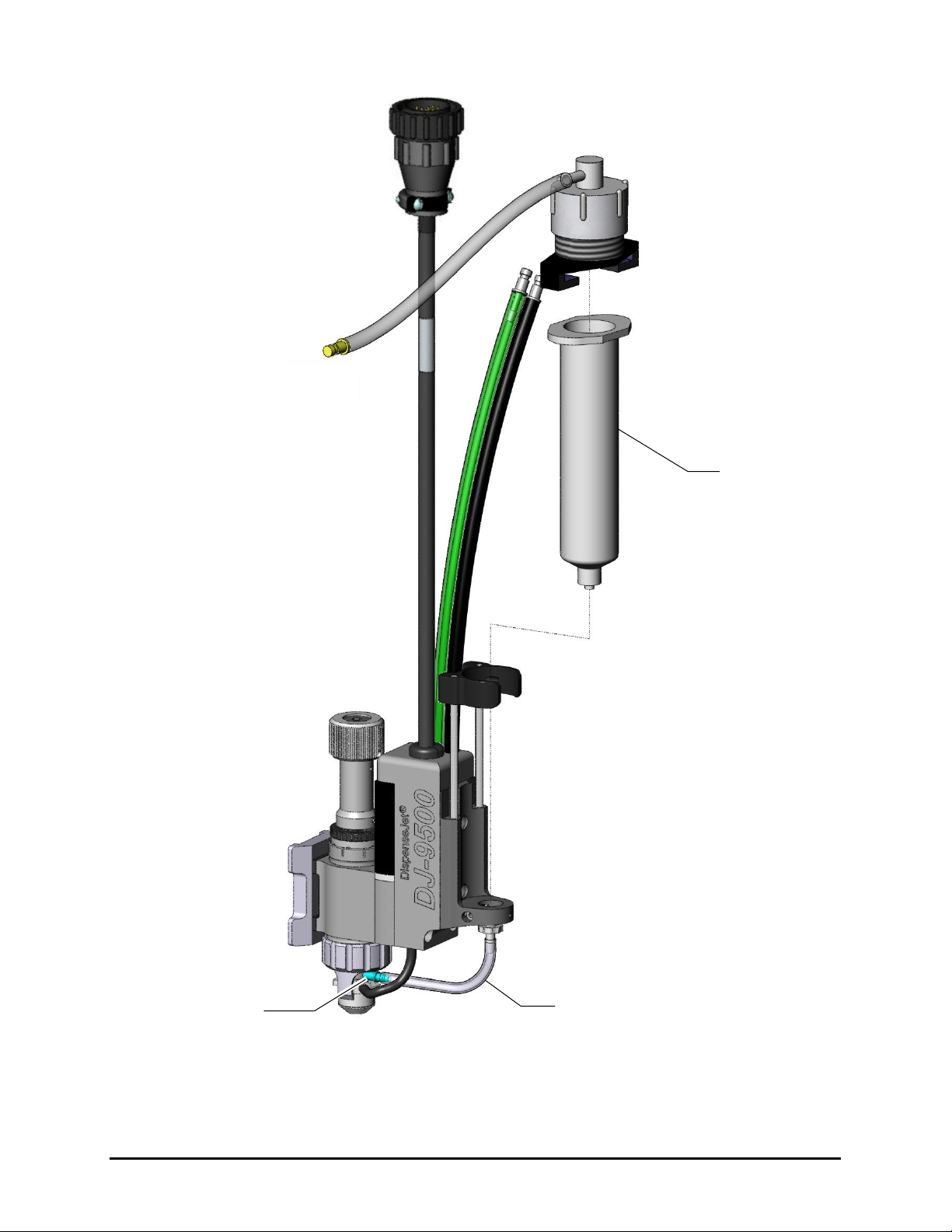
Figure 5-1 Connecting the Fluid Reservoir (30cc Fluid Tube w/o Heat Exchanger)
Feed Tube Assembly
Fluid Reservoir
Fluid Chamber
This manual suits for next models
2
Table of contents
Other Nordson ASYMTEK Dispenser manuals

Popular Dispenser manuals by other brands

Teal
Teal TEALwash Installation and operating instructions

BETCO
BETCO COMPASS Instructional guide

Parker
Parker SciLog LabTec Series Installation, Operation & Maintenance Instruction Manual

Nordson
Nordson freedom product manual

Cornelius
Cornelius NITROPRO MINI Quick reference guide

Animo
Animo CN5e user manual

U-Line
U-Line Rubbermaid H-3542 quick start guide

Cornelius
Cornelius Enduro-200 installation manual

Star Manufacturing
Star Manufacturing Peristaltic Heated Condiment Dispenser HPDE1 Brochure & specs

U-Line
U-Line EZ Pull Senior H-2534 quick start guide

ITALTINTO
ITALTINTO i253C user manual

U-Line
U-Line H-2895 manual


