Nordson Sealant Equipment Micro-Meter Series Reference guide

0LFUR0HWHU6HULHV'LVSHQVHU
&86720(5352'8&70$18$/
&20321(170$18$/31
,668('
For parts and technical support, cŽŶƚĂĐƚ 'ůŽďĂůƵƐŝŶĞƐƐ^ĞƌǀŝĐĞƐ;'^Ϳ at
(ϴϬϬ) 4ϯϯ-ϵϯϭϵ, or contact your local Nordson Sealant Equipment Representative.
7KLVGRFXPHQWLVVXEMHFWWRFKDQJHZLWKRXWQRWLFH
3OHDVHFKHFNZLWKFXVWRPHUVHUYLFHIRUWKHODWHVWYHUVLRQ
1RUGVRQ6HDODQW(TXLSPHQW٠:L[RP0LFKLJDQ٠86$

3DUW 1RUGVRQ&RUSRUDWLRQ
1RUGVRQ&RUSRUDWLRQZHOFRPHVUHTXHVWVIRULQIRUPDWLRQFRPPHQWVDQG
LQTXLULHVDERXWLWVSURGXFWV*HQHUDOLQIRUPDWLRQDERXW1RUGVRQFDQEH
IRXQGRQWKH,QWHUQHWXVLQJWKHIROORZLQJDGGUHVV
KWWSZZZQRUGVRQFRP
Notice
7KLVLVD1RUGVRQ&RUSRUDWLRQSXEOLFDWLRQZKLFKLVSURWHFWHGE\FRS\ULJKW
2ULJLQDOFRS\ULJKWGDWH1R SDUW RI WKLV GRFXPHQWPD\EH
SKRWRFRSLHGUHSURGXFHGRUWUDQVODWHGWRDQRWKHUODQJXDJHZLWKRXWWKH
SULRUZULWWHQFRQVHQWRI1RUGVRQ &RUSRUDWLRQ7KH LQIRUPDWLRQ FRQWDLQHG
LQWKLVSXEOLFDWLRQLVVXEMHFWWRFKDQJHZLWKRXWQRWLFH
Trademarks
0LFUR0HWHU1RUGVRQDQGWKH1RUGVRQORJRDUHUHJLVWHUHGWUDGHPDUNVRI1RUGVRQ
&RUSRUDWLRQ
$OORWKHUWUDGHPDUNVDUHWKHSURSHUW\RIWKHLUUHVSHFWLYHRZQHUV

7DEOHRI&RQWHQWV i
3DUW
E1RUGVRQ&RUSRUDWLRQ
Table of Contents
6DIHW\
4XDOLILHG3HUVRQQHO
,QWHQGHG8VH
5HJXODWLRQVDQG$SSURYDOV
3HUVRQDO6DIHW\
+LJKí3UHVVXUH)OXLGV
)LUH6DIHW\
+DORJHQDWHG+\GURFDUERQ6ROYHQW+D]DUGV
$FWLRQLQWKH(YHQWRID0DOIXQFWLRQ
'LVSRVDO
2SHUDWLRQ
'HVFULSWLRQ
&RQVXPDEOH,WHPV$QG&RPSRQHQW&OHDQLQJ
&RQVXPDEOH,WHPV
&RPSRQHQW&OHDQLQJ
(OHFWULFDO&RQQHFWLRQV
(OHFWULFDO:LULQJ
3UHVVXUH7UDQVGXFHU&DOLEUDWLRQ
0DLQWHQDQFH$QG&OHDQLQJ
0HWHULQJ&\OLQGHU2LOLQJ
2SHUDWLRQ
7URXEOHVKRRWLQJ
5HSDLU
%OHHG9DOYH5HSODFHPHQW$QG)OXVK3OXJ5HSODFHPHQW
'LVSHQVH9DOYH5HSODFHPHQW
'ULYH&RPSRQHQW5HSODFHPHQW
$FWXDWRU5HSODFHPHQW0LFURí0HWHU.$.DQG'.
$LU&\OLQGHU5HSODFHPHQW0LFURí0HWHU3.
$LU&\OLQGHU&DOLEUDWLRQ0LFURí0HWHU3.
)ORZ7XEH5HSODFHPHQW
'LVSHQVH)ORZ7XEHV
,QOHW)ORZ7XEHV
,QOHW9DOYH5HSODFHPHQW
0HWHULQJ&\OLQGHU5HSODFHPHQW
0HWHULQJ5RG5HSODFHPHQW
0LFURí0HWHU.DQG'.
0LFURí0HWHU$.3.
3UHVVXUH7UDQVGXFHU5HSODFHPHQW
9DOYH0DQLIROG5HSODFHPHQW
'LVDVVHPEO\DQG$VVHPEO\
0HWHULQJ&\OLQGHU
3DUWV
8VLQJWKH,OOXVWUDWHG3DUWV/LVW
&ROXPQ3DUWV/LVW
&XVWRPHU3URGXFW0DQXDO
0LFURí0HWHU.3DUWV,OOXVWUDWLRQ
0LFURí0HWHU.3DUWV/LVW
0LFURí0HWHU$.3DUWV,OOXVWUDWLRQ
0LFURí0HWHU$.3DUWV/LVW
0LFURí0HWHU'.3DUWV,OOXVWUDWLRQ
0LFURí0HWHU'.3DUWV/LVW
0LFURí0HWHU3.3DUWV,OOXVWUDWLRQ
0LFURí0HWHU3.3DUWV/LVW

7DEOHRI&RQWHQWV
ii
3DUW E1RUGVRQ&RUSRUDWLRQ
.LWV
0HWHULQJ&\OLQGHU6RIW*RRGV$QG5HEXLOG.LWV
,QFKPP6WURNH.LWV
,QFKPP6WURNH.LWV
6HQVRU.LWV
7RROV
6SHFLILFDWLRQV

Micro−Meter Series Dispenser 1
Part 7444756
E2019 Nordson Corporation
Micro−Meter Series Dispenser
Safety
Read and follow these safety instructions. Task- and equipment-specific
warnings, cautions, and instructions are included in equipment
documentation where appropriate.
Make sure all equipment documentation, including these instructions, is
accessible to all persons operating or servicing equipment.
Qualified Personnel
SEquipment owners are responsible for making sure that NordsonR
equipment is installed, operated, and serviced by qualified personnel.
Qualified personnel are those employees or contractors who are trained
to safely perform their assigned tasks. They are familiar with all relevant
safety rules and regulations and are physically capable of performing
their assigned tasks.
SAllow only qualified personnel to perform the tasks outlined in this
manual.
Intended Use
Use of Nordson equipment in ways other than those described in the
documentation supplied with the equipment may result in injury to persons
or damage to property.
Some examples of unintended use of equipment include:
SUsing incompatible materials
SMaking unauthorized modifications
SRemoving or bypassing safety guards or interlocks
SUsing incompatible or damaged parts
SUsing unapproved auxiliary equipment
SOperating equipment in excess of maximum ratings
SOnly for use in automated work cells with appropriate safety guarding
and lockout devices.

Micro−Meter Series Dispenser
2
Part 7444756 E2019 Nordson Corporation
Regulations and Approvals
Make sure all equipment is rated and approved for the environment in which
it is used. Nordson equipment warranties may be voided if instructions for
installation, operation, and service are not followed.
All phases of equipment installation must comply with all federal, state, and
local codes.
Personal Safety
To prevent injury, follow these instructions.
SSafety glasses are to be worn at all times while installing, servicing,
operating, or observing equipment. The sudden release of air or fluid
can cause damage to eyes.
SRelieve system and material pressure before disconnecting hoses.
SDo not operate equipment unless safety guards, doors, or covers are
intact and automatic interlocks are operating properly. Do not bypass or
disarm any safety devices.
SKeep clear of moving equipment. Before adjusting or servicing any
moving equipment, shut off the power supply and wait until the
equipment comes to a complete stop. Lock out power and secure the
equipment to prevent unexpected movement.
SRelieve (bleed off) hydraulic and pneumatic pressure before adjusting or
servicing pressurized systems or components. Disconnect, lock out, and
tag switches before servicing electrical equipment.
SOperating faulty electrostatic equipment is hazardous and can cause
electrocution, fire, or explosion. Make resistance checks part of your
periodic maintenance program.
SIf you receive even a slight electrical shock, shut down all electrical and
electrostatic equipment immediately. Do not restart the equipment until
the problem has been identified and corrected.
SObtain and read Safety Data Sheets (SDS) for all materials used. Follow
the manufacturer’s instructions regarding the safe handling and use of
materials. Use recommended personal protection devices.
SMake sure the dispensing area is adequately ventilated.
STo prevent injury, be aware of less-obvious dangers in the workplace
that often cannot be completely eliminated, such as hot surfaces, sharp
edges, energized electrical circuits, and moving parts that cannot be
enclosed or otherwise guarded for practical reasons.

Micro−Meter Series Dispenser 3
Part 7444756
E2019 Nordson Corporation
High−Pressure Fluids
High pressure fluids, unless they are safely contained, are extremely
hazardous. Always relieve fluid pressure before adjusting or servicing high
pressure equipment. A jet of high−pressure fluid can cut like a knife and
cause serious bodily injury, amputation, or death. Fluids penetrating the skin
can also cause toxic poisoning. If you suffer a fluid injection injury, seek
medical care immediately.
WARNING: Any injury caused by high pressure liquid can be serious. If you
are injured or even suspect an injury:
SGo to an emergency room immediately.
STell the doctor that you suspect an injection injury.
SInform medical staff regarding the type of material dispensed.
MEDICAL ALERT −AIRLESS SPRAY WOUNDS: NOTE TO A PHYSICIAN
Injection into the skin is a serious traumatic injury. It is important to treat the
injury surgically as soon as possible. Do not delay treatment to research
toxicity. Toxicity is a concern with some exotic coatings injected directly into
the bloodstream. Consultation with a plastic surgeon or a reconstructive
hand surgeon may be advisable. The seriousness of the wound depends on
where the injury is on the body, whether the substance hit something on its
way in and deflected causing more damage, and many other variables
including skin micro−flora residing in the plant or gun which are blasted into
the wound. If the injected material contains acrylic latex and titanium dioxide
which damages the tissue’s resistance to infection, bacterial growth will
flourish. The treatment that doctors recommend for an injection injury to the
hand includes immediate decompression of the closed vascular
compartments of the hand to release the underlying tissue distended by the
injection material, judicious wound debridement, and immediate antibiotic
treatment.

Micro−Meter Series Dispenser
4
Part 7444756 E2019 Nordson Corporation
Fire Safety
To avoid a fire or explosion, follow these instructions:
SShut down all equipment immediately if you notice static sparking or
arcing. Do not restart the equipment until the cause has been identified
and corrected.
SDo not smoke, weld, grind, or use open flames where flammable
materials are being used or stored.
SDo not heat materials to temperatures above those recommended by
the manufacturer. Make sure heat monitoring and limiting devices are
working properly.
SProvide adequate ventilation to prevent dangerous concentrations of
volatile materials or vapors. Refer to local codes or your SDS for
guidance.
SDo not disconnect live electrical circuits while working with flammable
materials. Shut off power at a disconnect switch first to prevent sparking.
SKnow where emergency stop buttons, shutoff valves, and fire
extinguishers are located. If a fire starts in a spray booth, immediately
shut off the spray system and exhaust fans.
SShutoff electrostatic power and ground the charging system before
adjusting, cleaning, or repairing electrostatic equipment.
SClean, maintain, test, and repair equipment according to the instructions
in your equipment documentation.
SUse only replacement parts that are designed for use with original
equipment. Contact your Nordson Representative for parts information
and advice.
SBe sure to have a fire extinguisher on hand. Ensure ventilation is
adequate and follow all other safety guidelines as recommended by the
chemical manufacturer.
Halogenated Hydrocarbon Solvent Hazards
Do not use halogenated hydrocarbon solvents in a pressurized system that
contains aluminum components. Under pressure, these solvents can react
with aluminum and explode, causing injury, death, or property damage.
Halogenated hydrocarbon solvents contain one or more of the following
elements:
Element Symbol Prefix
Fluorine F“Fluoro−”
Chlorine Cl “Chloro−”
Bromine Br “Bromo−”
Iodine I“Iodo−”
Check your material SDS or contact your material supplier for more
information. If you must use halogenated hydrocarbon solvents, contact
your Nordson Sealant representative for information about compatible
Nordson Sealant Equipment components.

Micro−Meter Series Dispenser 5
Part 7444756
E2019 Nordson Corporation
Action in the Event of a Malfunction
If a system or any equipment in a system malfunctions, shut off the system
immediately and perform the following steps:
SDisconnect and lock out electrical power. Close pneumatic shutoff
valves and relieve pressure.
SIdentify the reason for the malfunction and correct it before restarting the
equipment.
Disposal
Dispose of equipment and material used in operation and servicing
according to federal, state, and local codes.
Operation
CAUTION:
SPrime/purge system prior to commencing system operation.
SRelieve air and material pressure when equipment is not in use for
prolonged periods of time. Do not allow pressure to remain static when
equipment is idle as this may cause material to pack and harden.
Description
The Micro−Meter Series Dispenser (Micro−Meter) from Nordson Sealant Equipment advances robot
mounted dispensing by providing a smaller, lighter, and easier to mount component meter without sacrificing
volumetric accuracy or control in the dispense process. The Micro−Meter employs a linear servo actuator(s)
or an air cylinder to drive metering rods through a metering cylinder, controlling ratio, flow rate, and volume
dispensed per shot.
The benefits of the Micro−Meter are as follows:
SPositive rod metering technique provides unparalleled volumetric
displacement.
SAdvanced seal cartridge design with a flushable grease area, along with
hardened metering rods provide the most durable solution for abrasive
materials.
SDirect mounting of Nordson 2−component valves allows for flexibility in
application use.
SAvailable linear drive motor provides accurate dispensing with a high
degree of responsiveness.
SElectronic pressure monitoring and electric monitoring (servo models)
creates high visibility regarding fluid behavior, ensuring that anomalies
are recognized and data logged.
SThe wetted out section is comprised of stainless steel and inert
materials to ensure compatibility with all dispensing fluids.
Micro−Meter Series Dispenser
6
Part 7444756 E2019 Nordson Corporation
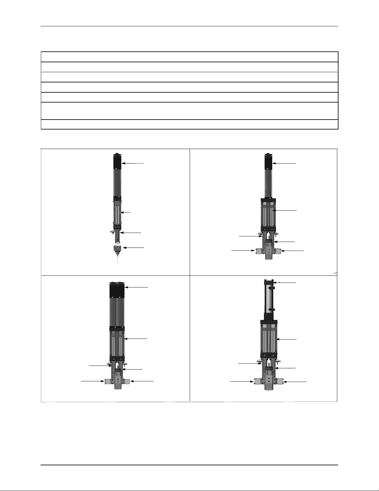
Table 1 Micro−Meter Major Components
Description
Actuator −Electric servo which facilitates metering rod movement.
Air cylinder −Pneumatically driven and generates movement of metering rods.
Dispense valve −Provides complete cut−off control over the application of metered material.
Inlet valve −Accommodates the intake of material from system supply.
Metering cylinder −Houses seal cartridge and cylinder sleeve. Displaces material allowing for the metering
of extremely small beads and dispense volumes.
Pressure transducer −Measures the force of material moving through the dispenser.
1K A2K
D2K P2K
Actuator
Single metering rod
Dispense valve
Actuator
Dual metering
rods
Inlet valve Inlet valve
Dispense valve
Dual actuators
Dual metering
rods
Inlet valve Inlet valve
Dispense valve
Air cylinder
Dual metering
rods
Inlet valve Inlet valve
Dispense valve
Metering cylinder Metering cylinder
Metering cylinder Metering cylinder
Figure 1 Micro−Meter Variations

Micro−Meter Series Dispenser 7
Part 7444756
E2019 Nordson Corporation
*Example−Refer to Parts, Metering Cylinder Soft Goods And Rebuild Kits for additional information.
Pressure transducer
Dispense valve*
Inlet valve*
Valve can be rotated
90 degrees
Dispense flow tube*
Outlet manifold*
Inlet flow tube*
Figure 2 Micro−Meter 1K Major Components Exploded View
*Example−Refer to Parts, Metering Cylinder Soft Goods And Rebuild Kits for additional information.
Valve can be rotated
90 degrees
Pressure transducer
Outlet manifold*
Dispense valve*
Dispense flow tube*
Inlet flow tube*
Plug
Figure 3 Micro−Meter A2K, D2K. P2K Major Components Exploded View

Micro−Meter Series Dispenser
8
Part 7444756 E2019 Nordson Corporation
Section B−B
5 inch stroke Section B−B
2.5 inch stroke
Bleed valve located
in upper port
Bleed valve located
in lower port
Plug located in lower port
Plug located in upper port
option option
The Micro−Meter can be set up to accommodate small and large shot sizes. By reducing the overall volume in the
cylinder, a more accurate micro−shot can be maintained and repeated. To accomplish this, a seal cartridge is used
that places the seals at the halfway point in the metering cylinder.
Figure 4 Micro−Meter Stroke Options

Micro−Meter Series Dispenser 9
Part 7444756
E2019 Nordson Corporation
Consumable Items And Component Cleaning
Consumable Items
Table 2 Consumable Items
Item Part Application
*Donnelly Bros. Inc. −All Purpose Grease [(APG#2)
(optional) (except Europe and U.K.)]
*Sonneborn White Petroleum Jelly SnowwhiteRN
[(optional) (Europe and U.K)]
*Seal Sav’r Oil
7426965
N/A
7428656
Applied to flow tube O−rings and me-
tering cylinder wearable parts such as
O−rings, and seals. Applied to pressure
transducer port.
Loctiter242/248 N/A Apply when assembly drawing re-
quires. Used for locking fasteners.
Loctite 577 N/A Used for pressure transducer and pipe
plugs.
*Caution: Check your MSDS or contact your material
supplier for grease/oil compatibility.
Component Cleaning
The tools shown in Table 3 are utilized to clean and service various system
components.
WARNING:
SAllow only qualified personnel to perform the following tasks. Follow the
safety instructions in this document and all other related documentation.
SRelieve material pressure prior to servicing system components.
SRelieve system air pressure prior to servicing system components.
SDisconnect and lock out power to the Micro−Meter prior to servicing
system components.
CAUTION:
SDo not allow any lubricants to enter fluid passageways during repair.
SRelieve air and material pressure when equipment is not in use for
prolonged periods of time. Do not allow pressure to remain static when
equipment is idle as this may cause material to pack and harden.
Micro−Meter Series Dispenser
10
Part 7444756 E2019 Nordson Corporation
Table 3 Cleaning Tools and Chemicals
Tool Name Type Part Number
Nylon and / or soft plastic bristle brushes Cleaning tools −
Plastic pick Metering cylinder and valve cleaning / re-
build tool
7439868
Electrical Connections
Electrical Wiring
Refer to System Manual wiring schematic for Micro−Meter wiring
information.
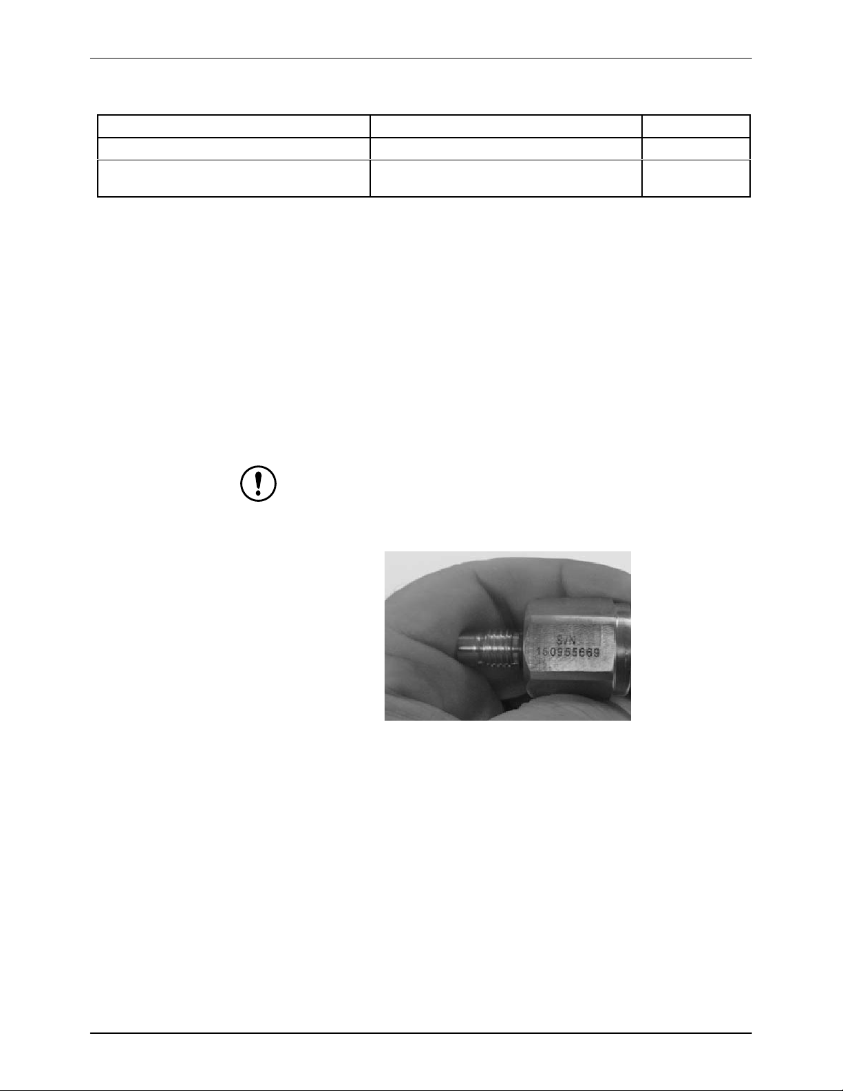
Pressure Transducer Calibration
Pressure transducers are individually calibrated and serial numbered at the
factory.
CAUTION: If an individual pressure transducer requires replacement,
calibration information has to be entered into the control panel.
1. Obtain factory serial number from pressure transducer. See Figure 5.
Figure 5 Pressure Transducer Serial Number
2. Utilize calibration record as a basis to enter control panel calibration
data.
3. Turn control panel OFF.
4. Install new pressure transducers(s).

Micro−Meter Series Dispenser 11
Part 7444756
E2019 Nordson Corporation
5. Connect pressure transducers to the control panel.
CAUTION: Ensure the high volume and low volume pressure transducers
are connected to the correct control panel leads.
6. Turn ON the control panel.
7. From the main menu of the control panel, proceed to:
SMain Menu
SSetup Login
SLevel 2 Setup (password required)
SPressure Sensor Calibration
8. Refer to the HMI screen display.
9. Ensure internal meter pressure is at or near zero psi.
10. For each pressure transducer, enter the ’0 psi Cal’ value and the ’Full
Scale psi’ value (250 psi) from the calibration sheet.
11. Adjust the ’Zero Offset’ until the ’Scaled Pressure’ at the top of the
screen reads zero.
Maintenance And Cleaning
WARNING:
SAllow only qualified personnel to perform the following tasks. Follow the
safety instructions in this document and all other related documentation.
SRelieve material pressure prior to servicing system components.
SRelieve system air pressure prior to servicing system components.
SDisconnect and lock out power to the Micro−Meter prior to servicing
system components.
CAUTION:
SDo not allow any lubricants to enter fluid passageways during repair.
SRelieve air and material pressure when equipment is not in use for
prolonged periods of time. Do not allow pressure to remain static when
equipment is idle as this may cause material to pack and harden.
Refer to the Quick Start Guide for additional operating instructions.
NOTE:
SThe frequencies listed are only guidelines. It’s recommended to inspect
components weekly. It may be necessary to adjust frequencies due to
the facility environment, process parameters, material being applied, or
experience.
SAlways listen for air leaks, keep your work area clean of material, and
check with the material supplier for specific cleaning procedures for the
material being utilized.

Micro−Meter Series Dispenser
12
Part 7444756 E2019 Nordson Corporation
Table 4 Preventative Maintenance Schedule
Component Task Completion Time Frequency
Actuator
Inspect for loose connections. In-
spect linear servo actuator rod for
damage.
Inspect: 10 Min.
Replace: 15−30 Min. Weekly
Air cylinder Inspect for air leaks. Inspect air cylin-
der rod for damage.
Inspect: 10 Min.
Replace: 15−30 Min. Weekly
Air fittings and
tubing Inspect for air leaks. Inspect: 5 Min.
Replace: 10−15 Min. Weekly
Inlet/dispense
valves
Inspect for air and material leaks. Inspect: 5 Min.
Replace: 15−30 Min. Weekly
Material fittings
and hoses Inspect for material leaks. Inspect: 10 Min.
Replace: Up to 1 hour Weekly
Metering
cylinder
Add appropriate oil or grease as
specified in Consumable Items And
Component Cleaning, Consumable
Items to metering cylinder fill port.
Refer to Maintenance And Cleaning,
Metering, Metering Cylinder Oiling for
additional information.
Inspect: 5 Min.
Replace: 10 Min. Weekly
Metering rod Inspect for damage to surface of rod. Inspect: 10 Min.
Replace: 30 Min. Weekly
Pressure trans-
ducer Inspect for material leaks. Inspect: 5 Min.
Replace: Up to 30 Min. Weekly

Micro−Meter Series Dispenser 13
Part 7444756
E2019 Nordson Corporation
Metering Cylinder Oiling
Front View Rear View
Add oil or grease to
fill port Weep hole
Caution: Check your MSDS or contact your material supplier for grease/oil compatibility. Add appropriate oil or
grease to metering cylinder O−rings and seals as specified in Consumable Items And Component Cleaning, Con-
sumable Items to metering cylinder fill port. Add zerk fittings to metering cylinder fill port to add grease. Add grease
or oil until it exits the weep holes located on the rear of the Micro−Meter. Connect a tube to the rear of the weep
hole (if necessary) to route oil or grease away from the meter.
*D2K meter shown; other meters similar.
Figure 6 Metering Cylinder Oiling
Operation
WARNING:
SAllow only qualified personnel to perform the following tasks. Follow the
safety instructions in this document and all other related documentation.
SRelieve material pressure prior to servicing system components.
SRelieve system air pressure prior to servicing system components.
SDisconnect and lock out power to the Micro−Meter prior to servicing
system components.
CAUTION:
SDo not allow any lubricants to enter fluid passageways during repair.
SRelieve air and material pressure when equipment is not in use for
prolonged periods of time. Do not allow pressure to remain static when
equipment is idle as this may cause material to pack and harden.
Refer to the Quick Start Guide for additional operating instructions.

Micro−Meter Series Dispenser
14
Part 7444756 E2019 Nordson Corporation
Troubleshooting
WARNING:
SAllow only qualified personnel to perform the following tasks. Follow the
safety instructions in this document and all other related documentation.
SRelieve material pressure prior to servicing system components.
SRelieve system air pressure prior to servicing system components.
SDisconnect and lock out power to the Micro−Meter prior to servicing
system components.
CAUTION:
SDo not allow any lubricants to enter fluid passageways during repair.
SRelieve air and material pressure when equipment is not in use for
prolonged periods of time. Do not allow pressure to remain static when
equipment is idle as this may cause material to pack and harden.
NOTE: These troubleshooting procedures cover only the most common
problems. If you cannot solve a problem with the information given here,
contact your local Nordson Representative for assistance.
Problem Possible Cause Corrective Action
Meter will not cycle
Blocked material path Ensure material is passing through all hoses.
Dispense valve not
opening
Ensure air is on. Inspect dispense valve for binding.
Inspect dispense valve piston for binding. Inspect
dispense valve piston O-ring for wear or damage.
Ensure there is sufficient air pressure. Ensure dispense
valve solenoid is functioning properly.
Actuator/air cylinder not
cycling
Inspect the power and controller connections are
properly fastened. Be sure there is sufficient power to
cycle the actuator shaft. Ensure sufficient air is supplied
to the air cylinder. Reference the equipment literature
provided with the System Manual.
Pressure transducer
reading low pressure
Inspect pressure transducer calibration. Inspect position
of the pressure transducer to ensure the to ensure the
part was installed properly. Ensure the pressure
transducer is properly functioning.
Supply equipment not
cycling
Ensure there is sufficient air pressure. Reference supply
equipment literature.
Meter Leakage
Loose fitting Isolate leak and tighten fitting.
Material metering
portion failure
Ensure all fittings are properly tightened.
Valve seal failure
Replace seal (s). Replace or repair scored or damaged
needle, if necessary. Replace or repair scored or
damaged sealing face, if necessary.

Micro−Meter Series Dispenser 15
Part 7444756
E2019 Nordson Corporation
Repair
WARNING:
SAllow only qualified personnel to perform the following tasks. Follow the
safety instructions in this document and all other related documentation.
SRelieve material pressure prior to servicing system components.
SRelieve system air pressure prior to servicing system components.
SDisconnect and lock out power to the Micro−Meter prior to servicing
system components.
CAUTION:
SDo not allow any lubricants to enter fluid passageways during repair.
SRelieve air and material pressure when equipment is not in use for
prolonged periods of time. Do not allow pressure to remain static when
equipment is idle as this may cause material to pack and harden.
SApply thread locker strictly in accordance to the replacement procedures
detailed in this section.
Bleed Valve Replacement And Flush Plug Replacement
See Figure 7.
WARNING:
SRelieve system air and material pressure before making any repairs.
Failure to observe this warning may result in serious personal injury.
SDisconnect and lock out power to the Micro−Meter prior to servicing
system components.
1. Remove meter assembly from automation source, if necessary.
2. Utilize wrench, Allen Key, or equivalent tools, to remove bleed valve (1)
or flush plug (2) from metering cylinder.

Micro−Meter Series Dispenser
16
Part 7444756 E2019 Nordson Corporation
NOTE: Bleed valve and flush plug removal from Micro−Meter 1K
shown;removal from Micro−Meter A2K, D2K, and P2K is similar.
7444678
1
2
*Inlet and dispense valves not shown for illustrative purposes only.
Figure 7 Bleed Valve And Flush Plug Replacement
3. Installation of the bleed valve and flush plug is in the reverse order of
removal. Note the following:
SHand tighten the bleed valve and flush plug until they are snug.
CAUTION: Ensure there are no leaks from the bleed valve and flush plug.
Dispense Valve Replacement
See Figure 8.
WARNING:
SRelieve system air and material pressure before making any repairs.
Failure to observe this warning may result in serious personal injury.
SDisconnect and lock out power to the Micro−Meter prior to servicing
system components.
1. Remove meter assembly from automation source, if necessary.
2. Remove air lines from dispense valve.
CAUTION:
SDo not kink or otherwise damage air lines.
SDo not reuse damaged air lines.
Table of contents
Other Nordson Sealant Equipment Dispenser manuals


