Nordson Sealant Equipment 801 User manual
Dual Servo 801 Dispenser
CUSTOMER PRODUCT MANUAL
COMPONENT MANUAL P/N: 7445673
ISSUED 3/2020
For parts and technical support, contact Global Business Services (GBS) at
(800) 433-9319, or contact your local Nordson Sealant Equipment Representative.
This document is subject to change without notice.
Please check with customer service for the latest version.
Nordson Sealant Equipment٠Wixom, Michigan٠U.S.A

Part 7444902 2019 Nordson Corporation
Nordson Corporation welcomes requests for information, comments, and
inquiries about its products. General information about Nordson can be
found on the Internet using the following address:
http://www.nordson.com.
Notice
This is a Nordson Corporation publication which is protected by copyright.
Original copyright date 08/2016. No part of this document may be
photocopied, reproduced, or translated to another language without the
prior written consent of Nordson Corporation. The information contained
in this publication is subject to change without notice.
Trademarks
Nordson and the Nordson logo are registered trademarks of Nordson
Corporation.
All other trademarks are the property of their respective owners.

Table of Contents i
Part 7445673
2020 Nordson Corporation
Table of Contents
Safety 1.................................................
Qualified Personnel 1...................................
Intended Use 1.........................................
Regulations and Approvals 2.............................
Personal Safety 2.......................................
High−Pressure Fluids 3..................................
Fire Safety 4...........................................
Halogenated Hydrocarbon Solvent Hazards 4..............
Action in the Event of a Malfunction 5.....................
Disposal 5.............................................
Operation 5............................................
Description 5.............................................
Consumable Items And Component Cleaning 7...............
Consumable Items 7....................................
Component Cleaning 8..................................
Electrical Connections 9.................................
Electrical Wiring 9....................................
Pressure Transducer Calibration 9......................
Maintenance And Cleaning 10...............................
Operation 12..............................................
Troubleshooting 13.........................................
Repair 14.................................................
Actuator Replacement 14.................................
Ball Screw and Ball Nut Assembly Replacement 16..........
Carriage Replacement 18.................................
Coupler Replacement 19.................................
Dispense Valve Replacement 19...........................
Inlet Valve Replacement 21...............................
Manifold Replacement 22.................................
Metering Cylinder Replacement 24.........................
Metering Rod Replacement 25............................
Pressure Transducer Replacement 26......................
Seal Cartridge Assembly Replacement 27...................
Upper Flange Replacement 28............................
Disassembly and Assembly 31...............................
Dispense Valve 31.......................................
Inlet Valve 34...........................................
Parts 36..................................................
Using the Illustrated Parts List 36..........................
3-Column Parts List 37.................................
Customer Product Manual 38.............................
Dual Servo 801 Dispenser Parts Illustration 38...............
Dual Servo 801 Dispenser Parts List 39.....................
Dispense Valve Parts Illustration 40........................
Inlet Valve Parts Illustration 42.............................
Inlet Valve Parts List 42...................................
Kits 44.................................................
Dispense Valve Service Kit 44...........................
Inlet Valve Service Kit 44................................
Seal Cartridge Assembly Service Kit (High Volume) 44......
Seal Cartridge Assembly Service Kit (Low Volume) 45......
Specifications 45...........................................
Dimensions 46.............................................

THIS PAGE HAS BEEN LEFT BLANK INTENTIONALLY.

Dual Servo 801 Dispenser 1
Part 7445673
2020 Nordson Corporation
Dual Servo 801 Dispenser
Safety
Read and follow these safety instructions. Task- and equipment-specific
warnings, cautions, and instructions are included in equipment
documentation where appropriate.
Make sure all equipment documentation, including these instructions, is
accessible to all persons operating or servicing equipment.
Qualified Personnel
Equipment owners are responsible for making sure that Nordson
equipment is installed, operated, and serviced by qualified personnel.
Qualified personnel are those employees or contractors who are trained
to safely perform their assigned tasks. They are familiar with all relevant
safety rules and regulations and are physically capable of performing
their assigned tasks.
Allow only qualified personnel to perform the tasks outlined in this
manual.
Intended Use
Use of Nordson equipment in ways other than those described in the
documentation supplied with the equipment may result in injury to persons
or damage to property.
Some examples of unintended use of equipment include:
Using incompatible materials
Making unauthorized modifications
Removing or bypassing safety guards or interlocks
Using incompatible or damaged parts
Using unapproved auxiliary equipment
Operating equipment in excess of maximum ratings
Only for use in automated work cells with appropriate safety guarding
and lockout devices.

Dual Servo 801 Dispenser
2
Part 7445673 2020 Nordson Corporation
Regulations and Approvals
Make sure all equipment is rated and approved for the environment in which
it is used. Nordson equipment warranties may be voided if instructions for
installation, operation, and service are not followed.
All phases of equipment installation must comply with all federal, state, and
local codes.
Personal Safety
To prevent injury, follow these instructions.
Safety glasses are to be worn at all times while installing, servicing,
operating, or observing equipment. The sudden release of air or fluid
can cause damage to eyes.
Relieve system and material pressure before disconnecting hoses.
Do not operate equipment unless safety guards, doors, or covers are
intact and automatic interlocks are operating properly. Do not bypass or
disarm any safety devices.
Keep clear of moving equipment. Before adjusting or servicing any
moving equipment, shut off the power supply and wait until the
equipment comes to a complete stop. Lock out power and secure the
equipment to prevent unexpected movement.
Relieve (bleed off) hydraulic and pneumatic pressure before adjusting or
servicing pressurized systems or components. Disconnect, lock out, and
tag switches before servicing electrical equipment.
Operating faulty electrostatic equipment is hazardous and can cause
electrocution, fire, or explosion. Make resistance checks part of your
periodic maintenance program.
If you receive even a slight electrical shock, shut down all electrical and
electrostatic equipment immediately. Do not restart the equipment until
the problem has been identified and corrected.
Obtain and read Safety Data Sheets (SDS) for all materials used. Follow
the manufacturer’s instructions regarding the safe handling and use of
materials. Use recommended personal protection devices.
Make sure the dispensing area is adequately ventilated.
To prevent injury, be aware of less-obvious dangers in the workplace
that often cannot be completely eliminated, such as hot surfaces, sharp
edges, energized electrical circuits, and moving parts that cannot be
enclosed or otherwise guarded for practical reasons.
Dual Servo 801 Dispenser 3
Part 7445673
2020 Nordson Corporation
High−Pressure Fluids
High pressure fluids, unless they are safely contained, are extremely
hazardous. Always relieve fluid pressure before adjusting or servicing high
pressure equipment. A jet of high−pressure fluid can cut like a knife and
cause serious bodily injury, amputation, or death. Fluids penetrating the skin
can also cause toxic poisoning. If you suffer a fluid injection injury, seek
medical care immediately.
WARNING: Any injury caused by high pressure liquid can be serious. If you
are injured or even suspect an injury:
Go to an emergency room immediately.
Tell the doctor that you suspect an injection injury.
Inform medical staff regarding the type of material dispensed.
MEDICAL ALERT − AIRLESS SPRAY WOUNDS: NOTE TO A PHYSICIAN
Injection into the skin is a serious traumatic injury. It is important to treat the
injury surgically as soon as possible. Do not delay treatment to research
toxicity. Toxicity is a concern with some exotic coatings injected directly into
the bloodstream. Consultation with a plastic surgeon or a reconstructive
hand surgeon may be advisable. The seriousness of the wound depends on
where the injury is on the body, whether the substance hit something on its
way in and deflected causing more damage, and many other variables
including skin micro−flora residing in the plant or gun which are blasted into
the wound. If the injected material contains acrylic latex and titanium dioxide
which damages the tissue’s resistance to infection, bacterial growth will
flourish. The treatment that doctors recommend for an injection injury to the
hand includes immediate decompression of the closed vascular
compartments of the hand to release the underlying tissue distended by the
injection material, judicious wound debridement, and immediate antibiotic
treatment.

Dual Servo 801 Dispenser
4
Part 7445673 2020 Nordson Corporation
Fire Safety
To avoid a fire or explosion, follow these instructions:
Shut down all equipment immediately if you notice static sparking or
arcing. Do not restart the equipment until the cause has been identified
and corrected.
Do not smoke, weld, grind, or use open flames where flammable
materials are being used or stored.
Do not heat materials to temperatures above those recommended by
the manufacturer. Make sure heat monitoring and limiting devices are
working properly.
Provide adequate ventilation to prevent dangerous concentrations of
volatile materials or vapors. Refer to local codes or your SDS for
guidance.
Do not disconnect live electrical circuits while working with flammable
materials. Shut off power at a disconnect switch first to prevent sparking.
Know where emergency stop buttons, shutoff valves, and fire
extinguishers are located. If a fire starts in a spray booth, immediately
shut off the spray system and exhaust fans.
Shutoff electrostatic power and ground the charging system before
adjusting, cleaning, or repairing electrostatic equipment.
Clean, maintain, test, and repair equipment according to the instructions
in your equipment documentation.
Use only replacement parts that are designed for use with original
equipment. Contact your Nordson Representative for parts information
and advice.
Be sure to have a fire extinguisher on hand. Ensure ventilation is
adequate and follow all other safety guidelines as recommended by the
chemical manufacturer.
Halogenated Hydrocarbon Solvent Hazards
Do not use halogenated hydrocarbon solvents in a pressurized system that
contains aluminum components. Under pressure, these solvents can react
with aluminum and explode, causing injury, death, or property damage.
Halogenated hydrocarbon solvents contain one or more of the following
elements:
Element Symbol Prefix
Fluorine F “Fluoro−”
Chlorine Cl “Chloro−”
Bromine Br “Bromo−”
Iodine I “Iodo−”
Check your material SDS or contact your material supplier for more
information. If you must use halogenated hydrocarbon solvents, contact
your Nordson Sealant representative for information about compatible
Nordson Sealant Equipment components.
Dual Servo 801 Dispenser 5
Part 7445673
2020 Nordson Corporation
Action in the Event of a Malfunction
If a system or any equipment in a system malfunctions, shut off the system
immediately and perform the following steps:
Disconnect and lock out electrical power. Close pneumatic shutoff
valves and relieve pressure.
Identify the reason for the malfunction and correct it before restarting the
equipment.
Disposal
Dispose of equipment and material used in operation and servicing
according to federal, state, and local codes.
Operation
CAUTION:
Prime/purge system prior to commencing system operation.
Relieve air and material pressure when equipment is not in use for
prolonged periods of time. Do not allow pressure to remain static when
equipment is idle as this may cause material to pack and harden.
Description
The Dual Servo 801 Dispenser is a positive displacement, single−acting meter/mix/dispense system
designed to produce a variable flow, one−component material. Positive rod displacement metering,
combined with dual servo technology, proportions material to the manufacturer’s exact volumetric ratio. A
signal from the actuator opens the dispense valve. This simultaneously sends a preset signals to the
respective servo motor and rotates the ball screw. Rotation of the ball screw, via the ball nut, causes the
carriage to move in a downward direction. Movement of the carriage drives the metering rod into the
metering cylinder and drives the positive displacement of material. The carriage continues to move
downward until it trips the proximity sensor. At this point, the dispense valve closes and the inlet valve
opens. The servo then causes the ball screw to spin the opposite direction, drawing the metering rod out of
the metering cylinder. Once the carriage reaches a predetermined location, the actuator stops turning, the
inlet valve closes, and the system is ready for the next dispense cycle.

Dual Servo 801 Dispenser
6
Part 7445673 2020 Nordson Corporation
Table 1 801 Dispenser Major Components
Description
Actuator − Electric servo which facilitates metering rod movement.
Dispense valve − Provides complete cut−off control over the application of metered material.
Inlet valve − Accommodates the intake of material from system supply.
Metering cylinder − Houses the seal cartridge assembly and cylinder sleeve. Capable of displacing ex-
tremely small dispense volumes.
Front Rear
Actuator
Dispense valve Inlet valve
Metering
cylinder
Metering rod
Figure 1 Dual Servo 801 Dispenser Major Components
Dual Servo 801 Dispenser 7
Part 7445673
2020 Nordson Corporation
Consumable Items And Component Cleaning
Consumable Items
Table 2 Consumable Items
Item Part Application
Donnelly Bros. Inc. − All Purpose Grease
[(APG#2) (optional) (except Europe and U.K.)]
Sonneborn White Petroleum Jelly SnowwhiteN
[(optional) (Europe and U.K.)]
7426965
N/A
Applied to transducer port, gauge
port, metering rod and wearable
parts such as O−rings, seals, and
bearings.
Donnelly Bros. Inc. − All Purpose Grease
[(APG#2) (optional) (except Europe and U.K.)]
Sonneborn White Petroleum Jelly SnowwhiteN
[(optional) (Europe and U.K.)]
7426965
N/A
1) Added to bearing housing to
ensure lubrication of metering cyl-
inder wearable components.
2) Option exists to add to grease
fitting located on metering cylinder
upper bearing housing. Refer to
Maintenance, Lubrication, Meter-
ing Cylinder for additional infor-
mation.
Kendall L−247 Super Blu
[(optional) (except Europe and U.K.)]
Sonneborn White Petroleum Jelly SnowwhiteN
[(optional) (Europe and U.K.)]
7437105
N/A
Used for bearings and ball screw.
Loctite242 N/A Apply when assembly drawing re-
quires. Used for locking fasteners.
Loctite248 N/A Apply when assembly drawing re-
quires. Used for locking fasteners.
Loctite577 7438517 Used for fluid section thread seal-
ant. Used for all air fittings.
Permabond003907−000001 Apply when assembly drawing re-
quires. Used for locking fasteners.
PTFE thread seal tape N/A Pneumatic section thread sealer.
Used for all air fittings.
Seal Sav’r Oil (optional) 7428656 Added to oil reservoir to ensure
lubrication of metering cylinder
wearable components.

Dual Servo 801 Dispenser
8
Part 7445673 2020 Nordson Corporation
Component Cleaning
The tools shown in Table 3 are utilized to clean and service various system
components.
WARNING:
Allow only qualified personnel to perform the following tasks. Follow the
safety instructions in this document and all other related documentation.
Relieve material pressure prior to servicing system components.
Relieve system air pressure prior to servicing system components.
Disconnect and lock out power to the 801 Dispenser prior to servicing
system components.
CAUTION:
Do not allow any lubricants to enter fluid passageways during repair.
Relieve air and material pressure when equipment is not in use for
prolonged periods of time. Do not allow pressure to remain static when
equipment is idle as this may cause material to pack and harden.
Table 3 Cleaning Tools and Chemicals
Tool Name Type Part Number
Nylon and / or soft plastic bristle brushes Cleaning tools −
Plastic pick Metering cylinder and valve cleaning / re-
build tool 7439868
Dual Servo 801 Dispenser 9
Part 7445673
2020 Nordson Corporation
Electrical Connections
Electrical Wiring
Refer to System Manual wiring schematic for 801 Dispenser wiring
information.
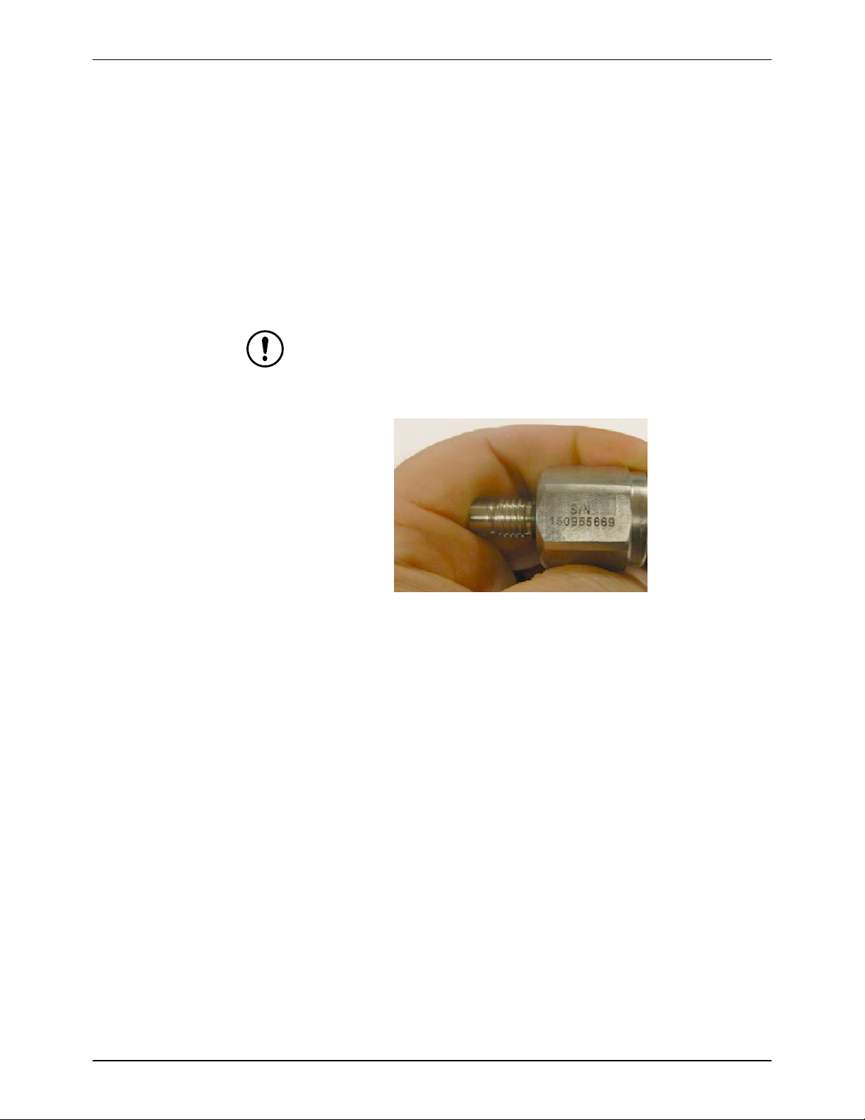
Pressure Transducer Calibration
Pressure transducers are individually calibrated and serial numbered at the
factory.
CAUTION: If an individual pressure transducer requires replacement,
calibration information has to be entered into the control panel.
1. Obtain factory serial number from pressure transducer. See Figure 2.
Figure 2 Pressure Transducer Serial Number
2. Utilize calibration record as a basis to enter control panel calibration
data.
3. Turn control panel OFF.
4. Install new pressure transducers(s).

Dual Servo 801 Dispenser
10
Part 7445673 2020 Nordson Corporation
5. Connect pressure transducers to the control panel.
CAUTION: Ensure the high volume and low volume pressure transducers
are connected to the correct control panel leads.
6. Turn ON the control panel.
7. From the main menu of the control panel, proceed to:
Main Menu
Setup Login
Level 2 Setup (password required)
Pressure Sensor Calibration
8. Refer to the HMI screen display.
9. Ensure internal meter pressure is at or near zero psi.
10. For each pressure transducer, enter the ’0 psi Cal’ value and the ’Full
Scale psi’ value (250 psi) from the calibration sheet.
11. Adjust the ’Zero Offset’ until the ’Scaled Pressure’ at the top of the
screen reads zero.
Maintenance And Cleaning
WARNING:
Allow only qualified personnel to perform the following tasks. Follow the
safety instructions in this document and all other related documentation.
Relieve material pressure prior to servicing system components.
Relieve system air pressure prior to servicing system components.
Disconnect and lock out power to the 801 Dispenser prior to servicing
system components.
CAUTION:
Do not allow any lubricants to enter fluid passageways during repair.
Relieve air and material pressure when equipment is not in use for
prolonged periods of time. Do not allow pressure to remain static when
equipment is idle as this may cause material to pack and harden.
Refer to the Quick Start Guide for additional operating instructions.
NOTE:
The frequencies listed are only guidelines. It’s recommended to inspect
components weekly. It may be necessary to adjust frequencies due to
the facility environment, process parameters, material being applied, or
experience.
Always listen for air leaks, keep your work area clean of material, and
check with the material supplier for specific cleaning procedures for the
material being utilized.
Dual Servo 801 Dispenser 11
Part 7445673
2020 Nordson Corporation
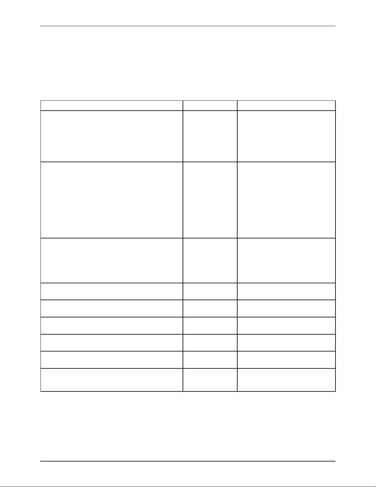
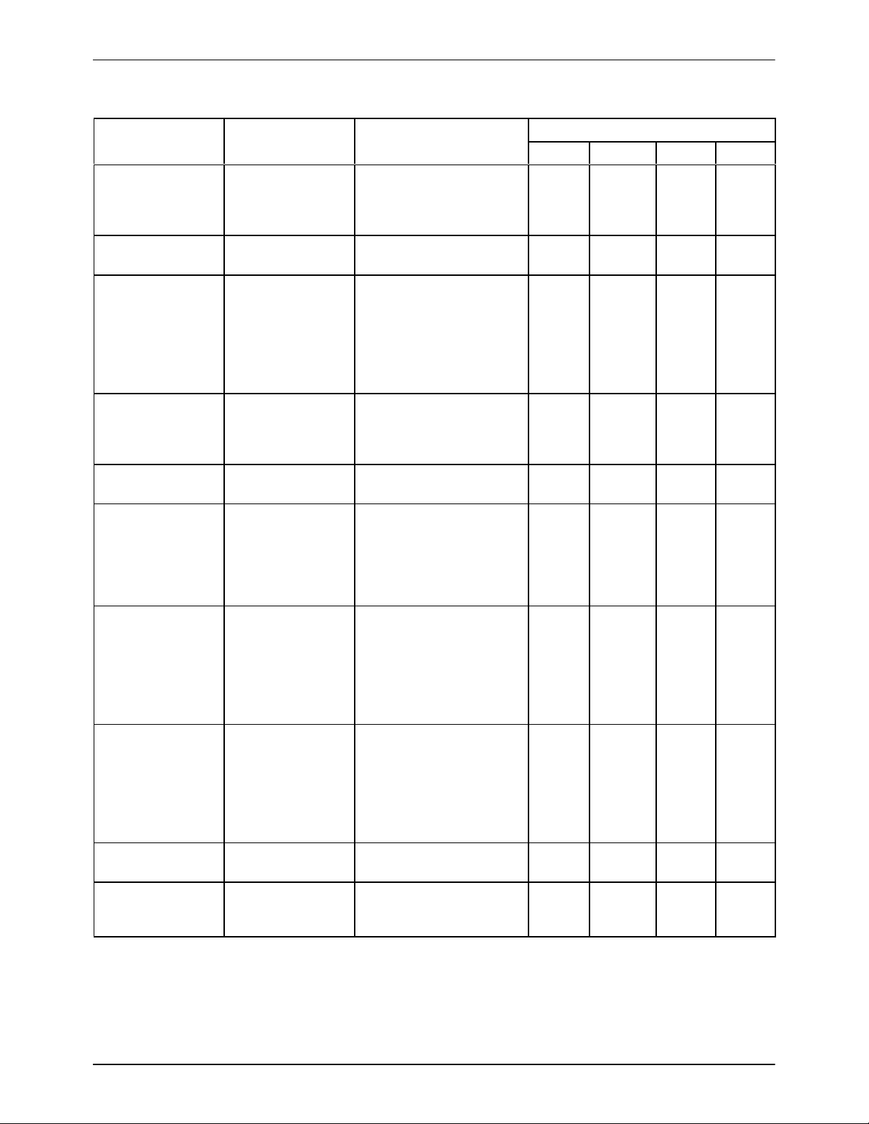
Table 4 Preventative Maintenance Schedule
Component Task Completion Time Frequency
Weekly Monthly Yearly Cycles
Actuator Inspect for loose
connections. In-
spect actuator rod
for damage.
Inspect: 10 Min.
Replace: 30−45 Min. ●
Air fittings and
tubing Inspect for air
leaks. 5 Min. ●
Ball screw
Check for damage
and replace dam-
aged components.
Lubricate ball
screw with Kendall
L−247 Super
Blu.
Inspect: 5 Min.
Apply Grease: 10 Min.
Replace: 30 − 60 Min. ●
Inlet/dispense
valves
Check for leakage
at the weep holes.
Use service kit, if
necessary.
Inspect 5 Min
Replace: 30 − 60 Min. ●
Material fittings
and hoses Check for material
leaks. 5 Min. ●
Material manifold
Check for leakage
and tighten any
loose valve
mounting screws.
Replace if neces-
sary.
Inspect: 5 Min.
Tighten: 5 Min.
Replace: 30 − 60 Min.
●
Metering cylinder
Inspect for leaks
and to damage re-
garding interior
sealing surfaces.
Replace metering
cylinder, if neces-
sary.
Inspect: 15−30 Min.
Replace: 2 −3 Hrs. ●
Metering rod
Inspect for dam-
age to surface of
rod. Prevent any
bypassed or
leaked material
from leaking onto
the rod.
Inspect: 10 Min.
Replace: 30 Min. ●
Pressure
transducer Check for material
leaks. 5 Min. ●
Seal cartridge
wet cups Keep wet cups ¾
full with Seal Sav’r
oil. Inspect: 5 Min.
Replace: Up to 30 Min. ●

Dual Servo 801 Dispenser
12
Part 7445673 2020 Nordson Corporation
Operation
WARNING:
Allow only qualified personnel to perform the following tasks. Follow the
safety instructions in this document and all other related documentation.
Relieve material pressure prior to servicing system components.
Relieve system air pressure prior to servicing system components.
Disconnect and lock out power to the 801 Dispenser prior to servicing
system components.
CAUTION:
Do not allow any lubricants to enter fluid passageways during repair.
Relieve air and material pressure when equipment is not in use for
prolonged periods of time. Do not allow pressure to remain static when
equipment is idle as this may cause material to pack and harden.
Refer to the Quick Start Guide for additional operating instructions.

Dual Servo 801 Dispenser 13
Part 7445673
2020 Nordson Corporation
Troubleshooting
WARNING:
Allow only qualified personnel to perform the following tasks. Follow the
safety instructions in this document and all other related documentation.
Relieve material pressure prior to servicing system components.
Relieve system air pressure prior to servicing system components.
Disconnect and lock out power to the 801 Dispenser prior to servicing
system components.
CAUTION:
Do not allow any lubricants to enter fluid passageways during repair.
Relieve air and material pressure when equipment is not in use for
prolonged periods of time. Do not allow pressure to remain static when
equipment is idle as this may cause material to pack and harden.
NOTE: These troubleshooting procedures cover only the most common
problems. If you cannot solve a problem with the information provided here,
contact your local Nordson Representative for assistance.
Problem Possible Cause Corrective Action
Meter will not cycle
Blocked material path Ensure material is passing through all hoses.
Dispense valve not
opening
Ensure air is on. Inspect dispense valve for binding.
Inspect dispense valve piston for binding. Inspect
dispense valve wearable components for wear or
damage. Ensure there is sufficient air pressure. Ensure
dispense valve solenoid is functioning properly. Check
for material hardening.
Actuator not cycling Ensure power and controller connections are properly
fastened. Be sure there is sufficient power to cycle the
actuator shaft. Reference equipment literature provided
with the System Manual.
Pressure transducer
reading low pressure
Inspect pressure transducer calibration. Inspect position
of the pressure transducer to ensure the part was
installed properly. Ensure the pressure transducer is
properly functioning.
Supply equipment not
cycling Ensure there is sufficient air pressure. Reference supply
equipment literature.
Meter Leakage
Loose fitting Isolate leak(s) and tighten fitting(s).
Material metering
portion failure Ensure all fittings are properly tightened.
Valve seal failure Inspect and replace seal(s) and/or other valve wearable
components.
Dual Servo 801 Dispenser
14
Part 7445673 2020 Nordson Corporation
Repair WARNING:
Allow only qualified personnel to perform the following tasks. Follow the
safety instructions in this document and all other related documentation.
Relieve material pressure prior to servicing system components.
Relieve system air pressure prior to servicing system components.
Disconnect and lock out power to the 801 Dispenser to servicing system
components.
CAUTION:
Do not allow any lubricants to enter fluid passageways during repair.
Relieve air and material pressure when equipment is not in use for
prolonged periods of time. Do not allow pressure to remain static when
equipment is idle as this may cause material to pack and harden.
Apply thread locker strictly in accordance to the replacement procedures
detailed in this section.
Actuator Replacement
See Figures 3 and 4.
WARNING:
Relieve system air and material pressure before making any repairs.
Failure to observe this warning may result in serious personal injury.
Disconnect and lock out power to the meter prior to servicing system
components.
1. Disconnect actuator cables.
2. Remove all guards from the meter.
3. Remove the lower coupler socket head cap screw (1). See Figure 3.
NOTE:
Utilize upper flange access hole to remove lower coupler socket head
cap screw.
Rotate the ball screw until the coupler socket head cap screw aligns with
the upper flange access hole.

Dual Servo 801 Dispenser 15
Part 7445673
2020 Nordson Corporation
1Upper flange
Figure 3 Coupler Socket Head Cap Screw
4. Remove socket head cap screw (5) and washer (4) securing actuator (1)
to upper flange (4). See Figure 4.
5. Separate actuator (1) from upper flange (3). See Figure 4.
NOTE: The actuator (1) is removed with the coupler (2) attached. See
Figure 4.
6. Remove the coupler (2) from actuator (1). See Figure 4.
1
2
3
4
5
Figure 4 Actuator Replacement

Dual Servo 801 Dispenser
16
Part 7445673 2020 Nordson Corporation
7. Installation of the actuator is in the reverse order of removal. Note the
following:
CAUTION:
Apply Loctite 242 or 248, or equivalent thread locker, to socket head cap
screws securing actuator to upper flange.
Allow Loctite 242 or 248, or equivalent thread locker, to fully cure prior to
utilizing system.
Tighten actuator−to−upper flange socket head cap screws to 2.4 Nm
(20.8 in.−lb).
Hand tighten coupler socket head cap screw until it is snug.
Ball Screw and Ball Nut Assembly Replacement
See Figures 5 and 6.
WARNING:
Relieve system air and material pressure before making any repairs.
Failure to observe this warning may result in serious personal injury.
Disconnect and lock out power to the meter prior to servicing system
components.
1. Remove upper flange. Refer to Repair, Upper Flange Replacement for
upper flange replacement procedure.
2. Remove socket head cap screw (1) and washer (2) securing ball nut (3)
to carriage (4). See Figure 5.
1
2
3
4
*Single servo 801 Dispenser shown; Dual Servo 801 Dispenser
is similar.
Figure 5 Ball Screw Replacement
Table of contents
Other Nordson Sealant Equipment Dispenser manuals


Popular Dispenser manuals by other brands


Tuthill
Tuthill Fill-Rite Owners installation, operation, and safety manual

Idex
Idex Fast & Fluid X-SMART Original manual

Stoelting
Stoelting F131-YG2 Operator's manual

Sartorius
Sartorius rLine 5-200ul LS Technical user's manual

BOWMAN
BOWMAN NC010-0111 manual

FIFO Innovations
FIFO Innovations SAUCE GUN BOTTLE manual


