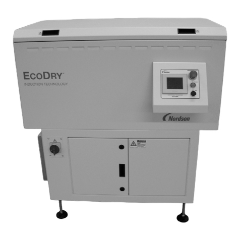
Nordson ISC2 Series User manual

ISC2 Series Induction Dryers
Customer Product Manual
Part 1606739-01
Issued 01/15
NORDSON CORPORATION •AMHERST, OHIO •USA
For parts and technical support, call the
Finishing Customer Support Center at (800) 433-9319.
Check http://emanuals.nordson.com/finishing for the latest version.
This document is subject to change without notice.

Part 1606739-01 E2014 Nordson Corporation
tents
Table of Contents
Safety 1.......................................
Qualified Personnel 1.........................
Intended Use 1..............................
Regulations and Approvals 2..................
Personal Safety 2............................
High-Pressure Fluids 3.....................
Fire Safety 4................................
Halogenated Hydrocarbon Solvent Hazards 5.
Action in the Event of a Malfunction 5...........
Disposal 5..................................
Description 6..................................
Features 6..................................
Induction Dryer Components 7.................
Theory of Operation 8........................
Specifications 9..............................
Manufacturing Data Code 9.................
Operating Parameters 9....................
Power Supply Requirements 9..............
System Weight (Crated) 9..................
Installation 10..................................
Inspection 10.................................
Lift Points 10.................................
System Positioning and Mounting 11............
Flow Direction and Power Supply 11..........
Clearances 11.............................
Mounting and Line Connections 12...........
Coil Tray Installation 13........................
System Wiring 13.............................
Schematics and Wiring Diagrams 13..........
Power Input 14...............................
External Interlock 15..........................
Connecting the External Interlock 15..........
Disabling the External Interlock 16............
Optional Status Contact 16.....................
Motion Sensor 16.............................
Return Shipping Instructions 17.................
Domestic/USA 17..........................
Export 17.................................
Setup 18.......................................
Preparation 18................................
Language Selection 19........................
Option Setup 21..............................
Restore System Defaults 21.................
Motion Sensor Sensitivity Adjustment 22.........
Timer and Motion Sensitivity Settings 23.........
Motion Timer Setting 23.....................
Motion Detect Sensitivity Setting 23...........
External Interlock Activation 24...............
External Interlock Timer Setting (Optional) 24..
Temperature Offset Setting 25..................
Alarm and Temperature Display Settings 26
......
Product Temperature Setpoint 26.............
Temperature Alarm Delay 26.................
Temperature Display Selection 27............
Phase Control Select 27.....................
Line Speed Monitor Select 28................
Operation 29...................................
Operator Controls 29..........................
Startup 30...................................
ISC2 Run Mode 31............................
Adjusting the Temperature Setpoint 31........
High and Low Alarms 32.......................
Faults 32....................................
Navigation Screen 33..........................
Shutdown 33.................................
Maintenance 34................................
Monthly 34...................................
Quarterly 34..................................
Troubleshooting 35.............................
Repair 37......................................
Air Filter Replacement 37......................
Parts 38.......................................
Temperature Conversions 38....................
Celsius−Fahrenheit Temperature Table 38........
Conversion Equations 38......................
Contact Us
Nordson Corporation welcomes requests for information, comments, and
inquiries about its products. General information about Nordson can be
found on the Internet using the following address:
http://www.nordson.com.
Address all correspondence to:
Nordson Corporation
Attn: Customer Service
555 Jackson Street
Amherst, OH 44001
Notice
This is a Nordson Corporation publication which is protected by copyright.
Original copyright date 2014. No part of this document may be
photocopied, reproduced, or translated to another language without the
prior written consent of Nordson Corporation. The information contained
in this publication is subject to change without notice.
Trademarks
Nordson, the Nordson logo, and iDry are registered trademarks of
Nordson Corporation.

Change Record i
Part 1606739-01
E2014 Nordson Corporation
Change Record
Revision Date Change
01 01/15 New Release

Change Record
ii
Part 1606739-01 E2014 Nordson Corporation

ISC2 Series Induction Dryers 1
Part 1606739-01
E2014 Nordson Corporation
ISC2 Series Induction Dryers
Safety
Read and follow these safety instructions. Task- and equipment-specific
warnings, cautions, and instructions are included in equipment
documentation where appropriate.
Make sure all equipment documentation, including these instructions, is
accessible to persons operating or servicing equipment.
Qualified Personnel
Equipment owners are responsible for making sure that Nordson equipment
is installed, operated, and serviced by qualified personnel. Qualified
personnel are those employees or contractors who are trained to safely
perform their assigned tasks. They are familiar with all relevant safety rules
and regulations and are physically capable of performing their assigned
tasks.
Intended Use
Use of Nordson equipment in ways other than those described in the
documentation supplied with the equipment may result in injury to persons
or damage to property.
Some examples of unintended use of equipment include
Susing incompatible materials
Smaking unauthorized modifications
Sremoving or bypassing safety guards or interlocks
Susing incompatible or damaged parts
Susing unapproved auxiliary equipment
Soperating equipment in excess of maximum ratings

ISC2 Series Induction Dryers
2
Part 1606739-01 E2014 Nordson Corporation
Regulations and Approvals
Make sure all equipment is rated and approved for the environment in which
it is used. Any approvals obtained for Nordson equipment will be voided if
instructions for installation, operation, and service are not followed.
WARNING: Never disarm any diagnostic or interlock devices including but
not limited to the following:
SCurrent sensor
SOvertemperature switches
SAir pressure switches
SPower supply door safety switch
Disarming these devices will void the warranty and may cause personal
harm or equipment failure.
Personal Safety
To prevent injury follow these instructions.
SDo not operate or service equipment unless you are qualified.
SDo not operate equipment unless safety guards, doors, or covers are
intact and automatic interlocks are operating properly. Do not bypass or
disarm any safety devices.
SKeep clear of moving equipment. Before adjusting or servicing moving
equipment, shut off the power supply and wait until the equipment
comes to a complete stop. Lock out power and secure the equipment to
prevent unexpected movement.
SRelieve (bleed off) hydraulic and pneumatic pressure before adjusting or
servicing pressurized systems or components. Disconnect, lock out,
and tag switches before servicing electrical equipment.
SWhile operating manual spray guns, make sure you are grounded.
Wear electrically conductive gloves or a grounding strap connected to
the gun handle or other true earth ground. Do not wear or carry metallic
objects such as jewelry or tools.
SIf you receive even a slight electrical shock, shut down all electrical or
electrostatic equipment immediately. Do not restart the equipment until
the problem has been identified and corrected.
SObtain and read Material Safety Data Sheets (MSDS) for all materials
used. Follow the manufacturer’s instructions for safe handling and use
of materials, and use recommended personal protection devices.
SMake sure the spray area is adequately ventilated.
STo prevent injury, be aware of less-obvious dangers in the workplace
that often cannot be completely eliminated, such as hot surfaces, sharp
edges, energized electrical circuits, and moving parts that cannot be
enclosed or otherwise guarded for practical reasons.

ISC2 Series Induction Dryers 3
Part 1606739-01
E2014 Nordson Corporation
High-Pressure Fluids
High-pressure fluids, unless they are safely contained, are extremely
hazardous. Always relieve fluid pressure before adjusting or servicing high
pressure equipment. A jet of high-pressure fluid can cut like a knife and
cause serious bodily injury, amputation, or death. Fluids penetrating the
skin can also cause toxic poisoning.
If you suffer a fluid injection injury, seek medical care immediately. If
possible, provide a copy of the MSDS for the injected fluid to the health care
provider.
The National Spray Equipment Manufacturers Association has created a
wallet card that you should carry when you are operating high-pressure
spray equipment. These cards are supplied with your equipment. The
following is the text of this card:
WARNING: Any injury caused by high pressure liquid can be serious. If
you are injured or even suspect an injury:
SGo to an emergency room immediately.
STell the doctor that you suspect an injection injury.
SShow him this card
STell him what kind of material you were spraying
MEDICAL ALERT—AIRLESS SPRAY WOUNDS: NOTE TO PHYSICIAN
Injection in the skin is a serious traumatic injury. It is important to treat the
injury surgically as soon as possible. Do not delay treatment to research
toxicity. Toxicity is a concern with some exotic coatings injected directly into
the bloodstream.
Consultation with a plastic surgeon or a reconstructive hand surgeon may
be advisable.
The seriousness of the wound depends on where the injury is on the body,
whether the substance hit something on its way in and deflected causing
more damage, and many other variables including skin microflora residing
in the paint or gun which are blasted into the wound. If the injected paint
contains acrylic latex and titanium dioxide that damage the tissue’s
resistance to infection, bacterial growth will flourish. The treatment that
doctors recommend for an injection injury to the hand includes immediate
decompression of the closed vascular compartments of the hand to release
the underlying tissue distended by the injected paint, judicious wound
debridement, and immediate antibiotic treatment.

ISC2 Series Induction Dryers
4
Part 1606739-01 E2014 Nordson Corporation
Fire Safety
To avoid a fire or explosion, follow these instructions.
SGround all conductive equipment. Use only grounded air and fluid
hoses. Check equipment and workpiece grounding devices regularly.
Resistance to ground must not exceed one megohm.
SShut down all equipment immediately if you notice static sparking or
arcing. Do not restart the equipment until the cause has been identified
and corrected.
SDo not smoke, weld, grind, or use open flames where flammable
materials are being used or stored.
SDo not heat materials to temperatures above those recommended by
the manufacturer. Make sure heat monitoring and limiting devices are
working properly.
SProvide adequate ventilation to prevent dangerous concentrations of
volatile particles or vapors. Refer to local codes or your material MSDS
for guidance.
SDo not disconnect live electrical circuits when working with flammable
materials. Shut off power at a disconnect switch first to prevent
sparking.
SKnow where emergency stop buttons, shutoff valves, and fire
extinguishers are located. If a fire starts in a spray booth, immediately
shut off the spray system and exhaust fans.
SShut off electrostatic power and ground the charging system before
adjusting, cleaning, or repairing electrostatic equipment.
SClean, maintain, test, and repair equipment according to the instructions
in your equipment documentation.
SUse only replacement parts that are designed for use with original
equipment. Contact your Nordson representative for parts information
and advice.

ISC2 Series Induction Dryers 5
Part 1606739-01
E2014 Nordson Corporation
Halogenated Hydrocarbon Solvent Hazards
Do not use halogenated hydrocarbon solvents in a pressurized system that
contains aluminum components. Under pressure, these solvents can react
with aluminum and explode, causing injury, death, or property damage.
Halogenated hydrocarbon solvents contain one or more of the following
elements:
Element Symbol Prefix
Fluorine F “Fluoro-”
Chlorine Cl “Chloro-”
Bromine Br “Bromo-”
Iodine I “Iodo-”
Check your material MSDS or contact your material supplier for more
information. If you must use halogenated hydrocarbon solvents, contact
your Nordson representative for information about compatible Nordson
components.
Action in the Event of a Malfunction
If a system or any equipment in a system malfunctions, shut off the system
immediately and perform the following steps:
SDisconnect and lock out system electrical power. Close hydraulic and
pneumatic shutoff valves and relieve pressures.
SIdentify the reason for the malfunction and correct it before restarting the
system.
Disposal
Dispose of equipment and materials used in operation and servicing
according to local codes.

ISC2 Series Induction Dryers
6
Part 1606739-01 E2014 Nordson Corporation
Description
The ISC2 Series induction systems provide simple, efficient, and uniform
drying of side seam coatings and bottom spray coatings. The systems use
solid state induction heating to generate heat within the can body, drying the
coatings at various line speeds dependent on quantity of coil tray units. Coil
trays can be mounted in any position for maximum versatility.
1 M ISC2 Coil Tray
Power Supply
Operator Control Pedestal
Figure 1 ISC2 Series Induction Dryer
Features
Instant on/off When the line starts, heating within the can body starts instantly. Since heat is
created directly within the can surface, there is no thermal inertia. When the
line stops, heating instantly stops or continues per the preset time.
Energy savings Solid state induction heating is extremely efficient. Most of the power
consumed is directly realized as heat in the can body. When the line stops,
almost no power is consumed.
Reliability The solid state design of the dryers minimizes downtime. Fewer moving parts
equals less wear items.
Small footprint Due to the high efficiency of induction drying, the dryer is much smaller than a
conventional oven.
Temperature monitor An infrared sensor, located on the last coil tray, determines the temperature of
the can body. The temperature is displayed on the operator terminal.

ISC2 Series Induction Dryers 7
Part 1606739-01
E2014 Nordson Corporation
Induction Dryer Components
See Figure 2.
Component Description
Coil tray Contains the induction coils with high flow cooling fans.
Motion sensor A laser sensor that monitors the movement of the can body at the entrance to
the coil tray. The controller will only apply power to the induction coil when the
motion sensor detects product moving through the induction dryer.
Operator control
pedestal
Contains the operator touch screen interface with all the operator control
functions, including warnings and faults. The console includes an Emergency
Stop, Power, and Off pushbuttons.
Control enclosure/
power supply
Contains the system controller (PLC), cooling air filters and fan, power inverter
devices, and control circuit boards.
Temperature sensor Senses the product temperature at the exit end of the last coil tray.
Product Flow
Motion
Sensor Coil Tray
Temperature
Sensor
Operator Control
Pedestal
Control Enclosure/Power Supply
Figure 2 ISC2 Series Induction Dryer (shown with one coil tray)

ISC2 Series Induction Dryers
8
Part 1606739-01 E2014 Nordson Corporation
Theory of Operation
The induction coil is connected to the power supply, and the can bodies
travel below or above the coil. When the power supply applies an
alternating current, the coil generates an alternating magnetic field that cuts
through the side seam or dome of the can bodies dependent on the
application. This results in large eddy currents circulating within the can
bodies. The resistance to this circulating current results in heat that cures
the applied coating. In steel cans, there is also heat from magnetic
hysteresis. Careful coil and power supply design ensure close control of
heating rates and uniformity.
Power to the induction coils and distance between the coils and the can
bodies is adjusted during setup to provide the desired temperature of can
bodies exiting the induction dryer. In some cases, an infrared temperature
sensor can be used to provide over or under temperature safety shutdowns.
Accuracy of infrared sensing depends on matching the emissivity of the
product to the sensor.
A laser motion sensor is mounted at the front of the unit to constantly
monitor line movement. If the line stops, power to the induction coil is
stopped. When the line restarts, the inverter is immediately restarted.
WARNING: Never disarm any diagnostic or interlock devices including but
not limited to the following:
SCurrent sensor
SOver temperature switches
SAir pressure switches
SPower supply door safety switches
Disarming these devices will void the warranty and may cause personal
harm or equipment failure.

ISC2 Series Induction Dryers 9
Part 1606739-01
E2014 Nordson Corporation
Specifications
Manufacturing Data Code
Serial Number: BK X X X X −X X X
year month
Operating Parameters
Ambient temperature range: 5−45_C (40−112_F)
Humidity: 0−70% for full system functionality
Elevation (altitude): Less than 1524 m (5000 ft)
Above 1524 m (5000 ft) system must be
de-rated −contact your Nordson
representative
Power Supply Requirements
360-480 Vac 50 Hz or 440-480 Vac 60 Hz, 3 phase
Voltage is preset at factory per specification −NOT FIELD ADJUSTABLE
Class J Bussmann TCF fusing required
System Weight (Crated)
Varies, 363-635 kg (800-1400 lb)

ISC2 Series Induction Dryers
10
Part 1606739-01 E2014 Nordson Corporation
Installation
WARNING: Allow only qualified personnel to perform the following tasks.
Follow the safety instructions in this document and all other related
documentation.
Inspection
The ISC2 system is shipped assembled in a kit form. The coil trays must be
installed by the customer. Unpack and carefully inspect all components for
obvious shipping damage and shortages. If any damage or shortages are
observed, notify the shipper and your Nordson representative immediately.
NOTE: A 5/16-in. hex wrench is required to unlock and lock the control
enclosure doors.
Lift Points
The ISC2 power supply requires a lift truck to remove it from the crate. See
Figure 3 for lift points. The individual coil trays and operator control
pedestal can be manually removed from the crate.
Lift Points
Figure 3 Lift Points for ISC2 Power Supply

ISC2 Series Induction Dryers 11
Part 1606739-01
E2014 Nordson Corporation
System Positioning and Mounting
Flow Direction and Power Supply
ISC2 coil trays are non-directional.
1. After coil trays are positioned on the line, install the motion sensor on
the leading edge of first coil tray.
NOTE: On lines with conveyor speed greater than 15 m/minute
(16 ft/minute) the motion sensor should be positioned up stream.
2. Install infrared sensor on the trailing edge of the last coil tray.
3. For systems with multiple coil trays, coil trays are numbered to facilitate
wiring. Place on line accordingly.
4. Place the power supply within 3 m (10 ft) of the first coil tray. Install
leveling pads on the power supply, making sure there is a minimum
clearance of 50 mm (2 in). under the power supply for air flow.
Clearances
Coil trays
SProvide clearance around coil tray cooling fans.
SDo not obstruct or limit free air to the fans or coil tray exhaust
Power supply
SClear any obstruction from blower intake (filters) and vents on the top
and bottom of the cabinet
SProvide 1 m (39 in.) of clearance at the rear of the power supply to
remove the access panel for power and interlock connections and
repairs
SProvide 1 meter (39 in.) of clearance in front of the power supply to open
the enclosure doors
SProvide a minimum clearance of 50 mm (2 in.) under the power supply

ISC2 Series Induction Dryers
12
Part 1606739-01 E2014 Nordson Corporation
Mounting and Line Connections
Coil trays
SMount on adjustable mounts above or below the conveyor with the can
bodies
SMake wiring connections using the wiring schematic in the addendum
Power supply
SInstall within 3 m (10 ft) of the first coil tray
Operator control pedestal
SPre-wired
SAnchor to floor in desired location

ISC2 Series Induction Dryers 13
Part 1606739-01
E2014 Nordson Corporation
Coil Tray Installation
1. Connect the coil wiring to the terminals (1) located in the junction box (4)
on lid of the coil tray (2).
2. Use the wiring schematics in the addendum to complete wiring
connections.
CAUTION: Do not block air intake (3) or exhaust (6) air flow.
12 3 4
56
Figure 4 ISC2 Coil Tray
1. Terminals
2. ISC2 coil tray
3. Inlet air
4. Junction/terminal box
5. Mounting rail (both sides)
6. Exhaust air (both sides)
System Wiring
Schematics and Wiring Diagrams
Refer to the addendum to this manual for system schematics and wiring
diagrams.

ISC2 Series Induction Dryers
14
Part 1606739-01 E2014 Nordson Corporation
Power Input
See Figure 5 for connections. Service requirement is 360-480 Vac 50 Hz or
440-480 Vac 60 Hz, 3 phase at 50 A. Class J fusing required. Systems are
preset for voltage & frequency at the factory. Verify supply voltage with
wiring schematics in the addendum.
WARNING: If plant supply is not through current-limiting Class J 50 A
fusing, customer is required to follow arc flash hazard criteria and label
appropriately.
WARNING: Install a locking breaker or disconnect in the electrical supply
line ahead of the system so all power to the induction system can be
disconnected and locked out when repairs are made. All electrical
connections must be made according to code, including a proper ground
connection. Failure to observe this warning could result in severe personal
injury or death from electrical shock.
WARNING: DANGER! Line terminals remain live even with the power
supply main disconnect locked out in the Off position.
Line power is supplied to the system through a 3/4-in. (1.9 cm) conduit fitting
in the lower left-hand corner of the dryer exit end.
NOTE: The wire gauge must be copper and comply with local and national
electrical codes.
1. Route three #6 AWG (13.3 mm2) wires to the input terminal block (TBL)
on the input side of the line filter.
2. Route one #6 AWG (13.3 mm2) ground wire to the cabinet grounding
terminal (PE) located next to the input terminal block.
L1 L2 L3
Ground
Figure 5 Power and Ground Connections/Line Terminals

ISC2 Series Induction Dryers 15
Part 1606739-01
E2014 Nordson Corporation
External Interlock
The external interlock is an optional connection that indicates to the dryer
that the production line is running. When the interlock is used, the dryer
controller will not apply power to the induction coil if there is no interlock
signal.
CAUTION: Nordson engineering recommends that the external interlock be
connected and enabled. Without the interlock, a random trip of the line
motion sensor may cause the controller to apply power to the coil while the
line is stopped, which could overheat stationary can bodies near the coil.
Connecting the External Interlock
The external interlock requires an external 24 Vdc source at 100 mA to
power an internal relay coil (refer to Note below). The external 24 Vdc
power source is not referenced to the dryer ground. The interlock indicates
to the dryer system that the production line is running. Without this signal,
the controller will not apply power to the induction coil.
NOTE: The interlock relay coil is relay CR4 (IDEC part number RY22S).
Additional relay voltages are available through an IDEC distributor.
1. Locate the interlock terminal behind the control enclosure doors, in front
of the control panel on the right side.
2. See Figure 6. Drill a hole or use a knockout tool to bring the interlock
cable into the enclosure. Install a properly sized strain relief or conduit
connector in the knockout.
3. Connect the interlock wiring to the terminal TB31-T and TB32-B.
1
2
Figure 6 External Interlock and Status Contact Connections
1. External internal terminal TB31-T 2. Status contact terminal TB32-B

ISC2 Series Induction Dryers
16
Part 1606739-01 E2014 Nordson Corporation
Disabling the External Interlock
If the external interlock will not be used, set the ISC2 system to run with the
signal from the motion sensor only.
1. Use the touch screen to go to the Navigation screen.
2. Select Options to go to the Options Setup screen.
3. Select the External Run Signal button to toggle it to Ignored.
Optional Status Contact
See Figure 6. The status contact provides a Dryer Ready signal. It is used
in conjunction with the customer interlock. The contact indicates when the
dryer is off or in a fault condition. The contact is off when:
SThe dryer is turned off.
SAny fault on the operator control is activated.
Status contact connection: Terminal 32 output contact (output)
Motion Sensor
See Figure 7. The motion sensor requires field mounting and should be
located close to the entry end of the coil tray (coil tray number 1 for systems
with multiple trays.) On lines with conveyor speed greater than 15 m/minute
(50 ft/minute) the motion sensor should be positioned up stream to ensure
the coil tray is on prior to a can body entering the induction field.
Adjust the motion sensor sensitivity as described on page 22.
Figure 7 Motion Sensor Position
Table of contents
Other Nordson Dryer manuals
Popular Dryer manuals by other brands

Kenmore
Kenmore Elite Oasis 110.6703 Series quick start guide

Haier
Haier HDY-D60 owner's manual

Whirlpool
Whirlpool Easy Clean 100 Series Use and care guide

American Dryer Corp.
American Dryer Corp. PHASE 7 OPL user manual

Crosley
Crosley CD-3 2206675 Use & care guide

Philco
Philco PDC 72 Chiva owner's manual

LG
LG DLEY1901 E Series owner's manual

Marta
Marta MT-1950 user manual

Samsung
Samsung DV456 Series technical information

VALERA
VALERA 830.01/R Translation from original instructions

Intelligent Facility Solutions
Intelligent Facility Solutions g-force user manual

Kenmore
Kenmore 29-Inch Wide GAS DRYERS Owner's manual and installation instructions