VSP 310 Quick Start
Rev 1.0
Page2 of 3
Address:S603-604 Weiye Building Torch Hi-Tech Industrial Development Zone Xiamen,Fujian Province, P.R.C
Tel: 00865925771197 Fax:00865925771202
Step 8-power connector
Plug in power cord which has IEC connector, VSP 310
support AC power from 85 to 260 VAC,50-60Hz,
which means world wide compatible.
Step 5 LAN (Ethernet) port
Use CAT5 cross-cable standards such as the bottom. The device's
default IP address is 192.168.0.100. Users can use the RS232 or
USB interface to modify the IP address. CAT5 cross-line, refers to
the end of the T568A standard on one end for the T568B standard.
Ethernet control interface module for non-standard modules Step 1 output resolution
Push OUT button and use UP or DOWN button to go to
the right resolution for the monitor or display system,
and push SEL button to decide to go to the resolution.
VSP 310 support 8output format as following :
800x600x60Hz,1024×768×60Hz , 1280×768×60Hz
1280×1024×60Hz ,1440×900×60Hz, 1400×1050×60Hz
1920×1080×60Hz 1600×1200×60Hz
Output resolution should be the same or
bigger than monitor or display system resolution.。
NOTE
Step 2-Input Switch
PIN T568A
T568B
1绿白
桔白
2green
桔色
3桔白
绿白
4蓝色 蓝色
5蓝白 蓝白
6桔白 绿色
7棕白 棕白
8棕色 棕色
CAT5
T568A
standard one
end, other
end to
T568B
standard
crossover
cable
T568A T568B
Insert Twisted
Pair Wires
RJ-45
Connector
PIN
Step 7-Serial port NOTE
Step 6-USB connector
3 USB interface for computer software AVDSP
Console.exe control. USB interface, 11 and 16 for the
LED control system, control, use the USB cable
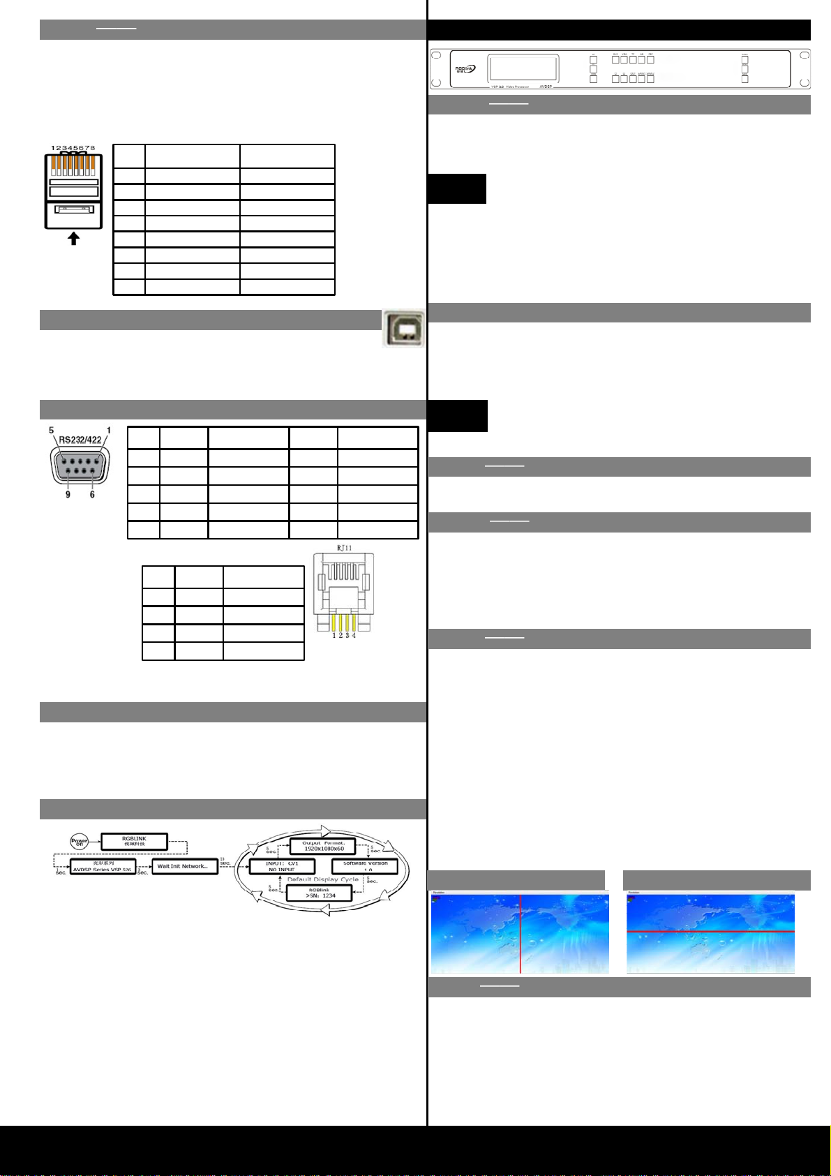
Powering up
Push power button switcher to ON position. LCD
module on the front panel will show RGBLINK and
VSP 310 model information, and go into self
verification before it load the last setting configuration
data and send the processed image to the target display
or device. For the first time running, CV1 input is the
default input source. User can operate with VSP 310
with local front panel and remote control with the
software run on the PC, remote control by RS232, USB
or TCP/IP.
Step 3 Pattern setting
Step 4 scale
Press TP button, enter Test Pattern menu 【Pattern】:
standard seven color bar
Push Scale button and go into scale setting menu. Use UP or
DOWN to go to Horizontal size, Vertical size, Horizontal
position, Vertical position setting page, and push SEL to
decide to set, and use UP or DOWN to change the size or
position value. Push SEL to send and exit from the setting.
First press the AB button to activate the main menu of
seamless transitions, press UP / DOWM button to enter the
main menu screen in different sub-effects, press the SEL
button to confirm the effects of the selected view mode is also
available on the effects menu. effects of the values set; such as
fade switch delay settings. Secondly, the touch input source
button to see a seamless transition effects.
Step6 Seemless switch
VSP 310 can handle any input source to fine 2 DVI outputs,
two DVI outputs which can each support full HD resolution
of 1920 * 1080 * 60Hz; and support for the second monitor
or projector-screen function.
press the MENU button to enter the main menu, press UP /
DOWN button to enter the sub-screen setup menu, press the
SEL button to enter the feature set to confirm, press UP /
DOWN button to set the horizontal or vertical screen split
screen. press the SEL button to view this feature; or directly
click the horizontal split-screen, vertical screen
Horizontal screen Vertical Screen
LED screen applications, the split-screen set of coordinates
set to support full-screen run
Step 5 separate setting
End 1
Wire color End 2
Wire color
1White-green White-orange
2
Green
Orange
3White-orange White-green
4Blue Blue
5White-blue White-blue
6Orange Green
7White-brown White-brown
8Brown Brown
RS-232 Function
2TX Transmit
3RX Receive
5GND Signal Ground
7--- Not used
8--- Not used
Pin RS-422 Function
TX- Transmit(-)
RX- Receive(-)
GND Signal Ground
RX+ Receive(+)
TX+ Transmit(+)
Insert Twisted
Pair Wires
RS232/RS422
Connector
Insert Twisted
Pair Wires
RJ11
Connector
RJ-11 Function
1
TX Transmit
2RX Receive
3
GND Signal Ground4
--- Not used
Pin
Local control -- Front Panel Operation
VSP 310 support DVI and VGA inputs, push DVI or
VGA button, switch to the corresponding input signal
and the signal output by setting the display resolution
and the SCALE value to the terminal device
Currently selected input signal when no signal
input, VSP 310 will remain displayed on a
static screen image.


