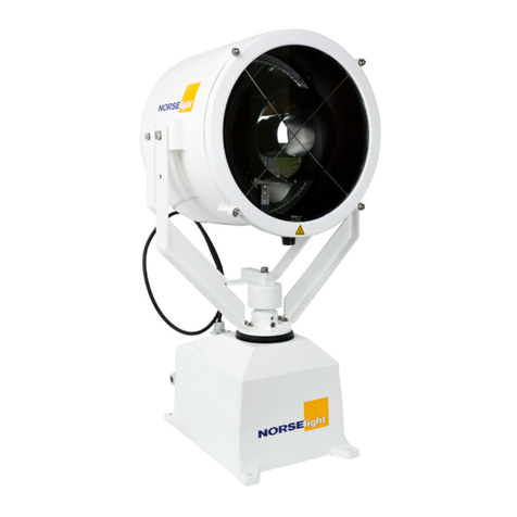
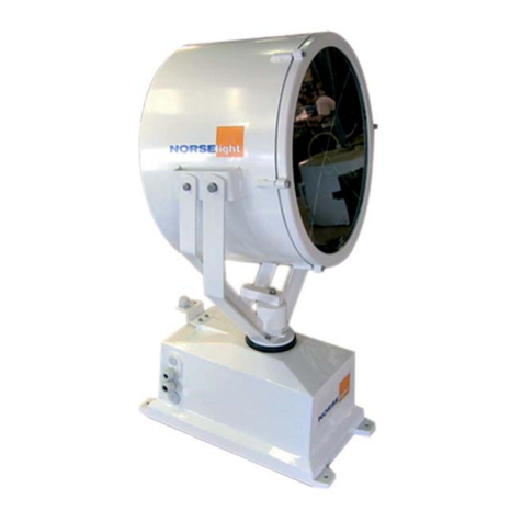
NORSELIGHT XENON SL40 R5 Instruction Manual

1
INSTALLATION & USER
MANUAL
SEARCHLIGHTS XENON SL40 R5

2
Technical Manual for
Xenon Searchlight
□XS 1000 R5
□XS 2000 R5
□1 x 230 VAC 50/60 Hz
□1 x 115 VAC 50/60 Hz
This manual refers to product:
Serial no.: ____________________
Controlled by: ____________________
Date: ____________________

3
Table of contents:
Introduction 4
1.0 General description 5
1.1 Options 6
2.0 Technical data and dimensions 7
2.1 Specifications power supply 8
2.2 Overall searchlight dimensions & electrical cable dimensions 9
2.3 Cut/out main/slave panel 10
2.4 Overall dimensions Power supply 11
3.0 Direction for use 16
3.1 Parameter setting for xbo HTP OFR 17
3.2 Program menu - Parameter setting 18
3.3 Operation modes 19
3.4 Program menu - Parameter mode setting 20
4.0 Electrical Installation 21
4.1 Layout XS1000 22
4.2 Layout XS2000 23
4.3 Wiring Searchlight XS1000 with integrated Power supply NP-0725 24
4.4 Wiring Searchlight XS2000 with external Power supply N3-80E 25
4.5 Wiring Searchlight XS1000 with external Powers supply PX-50N 26
4.6 Wiring Main panel XS and SH with focus 27
4.7 Power supply NP-0725 for 500-1000W 28
4.8 Power supply PX-50N for 1000W 29
4.9 Power supply N3-80E for 1600-2000W 30
4.10 Power supply EX-100 D/1 for 1000-3000W 31
5.0 Maintenance 32
5.1 Spare Parts List 33
5.2 Lamp replacement 34
5.3 Trouble shooting 37
6.0 Warranty 38

4
Introduction:
For more than 90 years,
Norselight have designed and manufactured lighting products for marine vessels.
Through ongoing customer focused product development, Norselight continue
to deliver quality products as demanded both at sea and on the rugged coastlines of Norway.
This commitment to quality and expertise provides the foundation for Norselight to be possibly the
world’s leading supplier of maritime lighting.
However, in order to stay in front, Norselight would very much appreciate all comments that you
may have regarding our quality products or services.
Customer Service:
The Customer Service department of GLAMOX Production GmbH & Co. KG will be pleased to
help you when ordering spare parts, for maintenance and repair work as well as in case of
problems and questions.
Manufacturer: Customer Service contact:
GLAMOX Production GmbH & Co. KG GLAMOX Marine and Offshore GmbH
Glasower Weg 5 Tel. : +49 421 48 93-0
Germany Internet: www.glamox.com/gmo
We would also like to use this opportunity to thank you for choosing Norselight.

5
1.0 General description:
Searchlight
The R5 searchlights XS 1000 and XS 2000,
are made from seawater resistant aluminium, welded and
finished with white powder coat.The forks are made of stainless steel
- The lamp housing contains one lamp, ignitor, silverplated glass-reflector,
hardened frontglass, noise filters and a focus-motor for adjustment of the light beam.
- The motor housing contains a complete gear with motors for
horizontal and vertical movement, a thermostat driven heating element and the electronic
control system.
Control Panel
Main Operation Panel.
it contains the following functions:
- Lamp On/Off
- Joystick for horizontal and vertical movement.
- Speed regulator for horizontal
- Focus +/- (light beam adjustment)
- Designed for console or bulkhead mounting.

6
1.1 Options
- Other RAL colours
- Upside down mounting
- Pedestal standard and custom sizes on request
- Special cable glands on request

7
2.0 Technical data and dimensions
General specifications searchlight unit:
Article no. Model Watt Voltage
500201340 SL 40 R5 XS1000 230V 1000W CFP 1000 230 VAC 50/60Hz
500201540 SL 40 R5 XS2000 230V 2000W CFP 2000 230 VAC 50/60Hz
500221340 SL40 R5 XS1000 115V 1000W CFP 1000 115 VAC 50/60Hz
Technical spec. for all XS models
IP Classification 56
Maximum ambient temperature 50ºC
Minimum ambient temperature -40ºC
Horizontal movement 360º
Vertical movement +-27,5º
Inclination speed V/H ≤4°/s
Colour RAL 9016
Forks Stainless steel
Technical spec.main panel
IP Classification 67 (front)
Maximum ambient temperature 50ºC
Minimum ambient temperature -20ºC
Connection terminal 12x max 1,5mm²
Dimensions 96 x 96 x 45mm
Power consumption 0

8
2.1 Technical data and dimensions
N3-80E 1600-2000W
Art No. 1009160
IP classification IP20
Temperature ambient 0°-40 ºC
Input Voltage 208-242VAC; 3-phase 50/60Hz
Cable input max Ø 27mm
Cable output (DC) max Ø 27mm
Cable remote signal max Ø 27mm
Dimensions ABH 320 x 380 x 770mm
Weight 105kg
Specifications Power supply:
NP-0725 500-1000W
Art No. 1009158
IP classification IP20
Temperature ambient -30°...50°C
Input Voltage 90-264VAC; single phase
Dimensions ABH 180 x 254 x 82,5mm
Weight 3,35kg
EX-100D/1 1000-3000W
Art No. 1009165
IP classification IP20
Temperature ambient -5°-45°C
Input Voltage 185-265VAC; single phase or double phase
Cable Input max Ø 8/20mm
Cable output (DC) max Ø 2 x 20mm
Cable remote signal max Ø 20mm
Dimensions ABH 265 x 436 x 440mm
Weight 19,5kg
PX-50N 1000W
Art No. 1009155 (115V) / 1009156 (230V)
IP classification IP20
Temperature ambient 0°-40°C
Input Voltage 100-132VAC; single phase
Input Voltage 208-230VAC; single phase
Cable input max Ø 24mm
Cable output (DC) max Ø 24mm
Cable remote signal max Ø 24mm
Dimensions ABH 245 x 595 x 238mm
Weight 63kg
NP-0725 500-1000W with heat sink
Art No. 8SL0018800
IP classification IP20
Temperature ambient -30°...50°C
Input Voltage 90-264VAC; single phase
Dimensions ABH 507 x 305 x 114mm
Weight 8,40kg

9
2.2 Overall searchlight dimensions & electrical cable dimensions
XS 1000-2000:
1
2
3
4←Front of motorhouse
←Common for all
R5 models.
Entry / Description 1 2 3 4
Cable gland M20 M20 M25 M32
Cable Ø min / max 6-13mm 6-13mm 9-17mm 13-21mm
Cable entry
(*Options are available)
Remote signal
to rectifier * LAN
24V DC /
115V AC /
230V AC *
DC from Xenon
rectifier
Entry / Description 1 2 3 4
Cable gland M20 M20 Blind plug Blind plug
Cable Ø min / max 6-13mm 6-13mm - -
Cable entry 115 V AC
230 V AC LAN - -
XS 1000
XS 2000

10
2.3 Cut/out main/slave panel
Hole dimensions for installing main panel:

11
2.4 Overall dimensions Power supply
For 500-1000W
NP-0725 (for mounting in the motor-house)
This single-phase rectifier has been designed to ensure correct operation and long life to short
arc Xenon lamps up to 1000W. It is characterized by galvanic insulation, a soft inrush current,
alow residual ripple value and a stable output current. Weight 3,35kg.
Further instructions in Installation guide for Rectifier see page 28.
A:180 mm
B:254 mm
H:82,5 mm
Note (1) The switch SW1 must remain in OFF position when the remote ON/OFF signal is
used.
1. Ta 50°C max running time until the searchlight will switch offis 2 hours.
2. Ta 45°C max running time until the searchlight will switch offis 6 hours.
3. Ta 35°C and less the searchlight is continuously running.
Note: After an automatic safety shutdown of the power supply due to overheating,
the input power of the search light (L,N) has to be interrupted and connected
again for a reset of the power supply.
(Keep the unit with the fan running for a few minutes and disconnect the
mains input for >5 seconds).
Note (2) Put the switch in the ON position to select the lamp power. The rest of switches
must remain in the OFF position.
Setting 500W Setting 1000W Setting 3000W

12
For 500-1000W
NP-0725 with heat sink
(for mounting in the motor-house)
This single-phase rectifier has been designed for higher temperature ensure correct operation and
long life to short arc Xenon lamps up to 1000W.
It is characterized by galvanic insulation, a soft inrush current, alow residual ripple value and a sta-
ble output current. Weight 8,4kg. Further instructions in Installation guide for Rectifier see page 28.
o
use
)
Settings: 30A = 500W
Settings: 50A = 1000W
→
→
Note: Current adjustments when the bulb is switched on.
The switch SW1 must remain in OFF position when the remote ON/OFF signal is used.
Setting 1000W
Setting 500W

13
PX-50N for 1000W
These extremely compact rectifiers for single-phase inputs have been designed to feed
1000W Xenon lamps, meeting the requirements of lamps manufacturers to ensure
correct operation and long life of the lamp. The units are fitted with a transformer with taps for
output lamp power regulation and a special circuit to avoid the lamp turn offduring the tap
switching.
The cabinet, equipped with carrying handles, permits an easy inspection of the inside components.
Weight 63kg.
Further instructions in Installation guide for Rectifier see page 29.
A:245mm
B:595mm
H:238mm

14
For 1600-2000W
N3-80E
These high quality rectifier power supplies have been expressly designed to ensure the correct
operation and long life of short arc Xenon lamps.
These units, developed to meet the recommendations of Xenon lamp manufacturers, are fitted
with special IREM transformers with adjustable magnetic shunt for continuous output regulation
over the entire operating range.
The new and peculiar design guarantees a low acoustical noise, i.e. less than 55dB(A).
The special design, including an auxiliary filter unit, ensures a low ripple with a negligible starting
energy. Weight 105kg.
Further instructions in Installation guide for Rectifier see page 30.
Adjust
current
by
turning
hand wheel.
Current
applied
to the lamp
should be
for.
A:320 mm
B:380 mm
H:770 mm
Electric installation
The main operation panel requires 24V DC connected in series with a 3A slow fuse
to the positive (+) conductor.
• The switch requires 24V DC in addition to grounding.
• Depending on the searchlight model it requires 115V AC or 230V AC.
• Power supplied to the power supply unit must be 3-phase and PE.
• Current supplied to the lamp unit must be specific, (see Technical data for specific type Omron).
Lamp set-point see page 30.
*To be able to turn offthe searchlight from the main panel, the switch on top of the power supply
N3-80 must be in position “0” (Zero).
Note: Disconnect the power when working on the equipment!
Electrical equipment must be installed by authorized personnel!
Check the polarity when connecting 24V DC!
All searchlight system equipment MUST BE connected to ground/earth!
*

15
For 1000-3000W
EX-100 D/1
This electronic power supply for single phase or double phase 230Vac 50/60Hz input has been
designed to feed from 1000W to 3000W short arc Xenon lamps, meeting all the requirements
of lamp manufacturers to ensure correct operation, long life to the lamp, and high reliability.
Weight 19,5kg. Further instructions in Installation guide for Rectifier see page 31.
Control devices
1. Synoptic panel
2. Output terminal block
3. Input terminal block
4. RS232 connector
5. Auxiliary connector

16
3.0 Directions for use
Parameter setting for xbo HTP OFR (only for: EX-100 D/1 with factory settings)
Lamp Pmax (operating range: 1000 and 2000W): max: power of the lamp.
When entered, an automatic control will avoid exceeding this value. Factory setting: is on 1000W.
Lamp lmax (operating range: 55A - 85A): max. admitted current of the lamp.
When entered, an automatic control will avoid exceeding this value. Factory setting: 55A.
Lamp lmax (operating range: 40 - 50A): min. admitted current of the lamp.
When entered, an automatic control will avoid exceeding this value. Factory setting: 40A.
Lamp stand-by (operating range lmax - lmin): lamp stand-by current when contacts 11 and 12 of
J/P2 have been closed. When the contacts are closed, an automatic control will be change the
current according to the admitted operating range. Factory setting: 40A.
Lamp set-point (operating range: lmax - lmin : value of the current delivered in output.
Factory setting: 40A.
Remarks:
1) When entering an lmax value lower than lmin , lmin will be set to lmax . Enter a new lmin value.
2) When entering a lmax exceeding lmax value, lmin will correspond to lmax .
EX-100 D/1
Lamp Pmax 2000W 1000W
Lamp Imax 85A 55A
Lamp Imin 50A 40A
Lamp stand-by 50A 40A
Lamp set-point 70A 50A

17
3.1 Program menu - Parameter setting
Example for 3000W Xenon

18
3.2 Program menu - Parameter setting

19
3.3 Operation modes
The tree operation modes can be used alternately but not all at the same time.
Act on the keys of the synoptic panel to shift from one mode to the other. The default mode is:
manual mode from synoptic panel.
When the RS232 serial line is ON, the operating parameters will be sent through this line.
From any mode, press the keys to change the operation mode.
Manual mode
Under this condition the lamp current setting is managed through the synoptic panel
(press left -decreasing- key and right -increasing- key). Press and hold one of the two setting keys
for at least 2 seconds, then enter the password within 30 seconds. The current setting is now
enable (a question mark is present on the right side of the current value).
The lamp current range has to be within 40A and 85A.
Press The ON/OFF key to switch on/offthe lamp.
Note:
under manual mode from remote control, the switching on must be forced by shorting contacts
3 and 4 of J/P2 connector. Please check the contacts 5 and 6 (set jumper), see page 30.
Under this operating condition the synoptic panel is no longer active.

20
3.4 Program menu - Parameter mode setting
This manual suits for next models
4
Table of contents
Other NORSELIGHT Floodlight manuals
Popular Floodlight manuals by other brands
HQ Power
HQ Power VDPLP1803RGB user manual
STUDIODUE
STUDIODUE RGBWA ArchiLed 300 User's and operator's manual

HAMPTON BAY
HAMPTON BAY HD39377 quick start guide
ARTFOX Lighting
ARTFOX Lighting LED Spot 150W RGBW Quad user manual
Powerplus
Powerplus LIGHT POWLI20100 quick start guide

COLORKINETICS
COLORKINETICS eW Burst Powercore gen2 installation instructions
