Nortek Security & Control 2GIG 2GIG-PAD1-345 User manual

Copyright © 2015 Nortek Security & Control LLC 1
2GIG-PAD1-345
WIRELESS KEYPAD
INSTALLATION INSTRUCTIONS
The2GIGWirelessKeypad(2GIG‐PAD1‐345)isawall‐mountedunit
designedforuseasasecondarykeypadforthe2GIGsecuritysystem.
ItcommunicateswiththeControlPanelusingthe345MHzfrequency
andprovidesuserswiththefollowingfeatures:
•ArmthesysteminStayorAwaymode
•Disarmthesystem
•ActivateFireandPanicemergencyfunctions
Figure 1 Wireless Keypad
Contents
Verifythatthepackageincludesthefollowing:
•1—WirelessKeypad
• 4—PlasticWallAnchorsandPhillipsHeadScrews
• 2—LithiumCoinBatteries(installed)
Programming
UsetheControlPaneltoconfiguretheWirelessKeypadtoworkwith
thesecuritysystem.Fordetails,see“Wireless(RF)Keypad
Programming”intheControlPanel’sInstallation&Programming
Guide.
Testing
BeforemountingtheWirelessKeypadinthedesiredlocation,verify
thatthelocationprovidesforgoodradiofrequency(RF)
communicationtotheControlPanel.
TotesttheWirelessKeypad:
1PlacetheControlPanelintosensortestmode.Forinstructions,
seetheControlPanel’sInstallation&ProgrammingGuide.
2PressandholdanynumerickeyontheWirelessKeypadforatleast
two(2)seconds.
3Listenforasirenorkeypadbeepstodeterminetheappropriate
response.Forinformation,seetheControlPanel’sInstallation&
ProgrammingGuide
4Exitsensortestmode.
NOTE: Itisstronglyrecommendedthatyouperformasystemtest
usingtheinstructionsintheControlPanel’sInstallation&
ProgrammingGuide.
Mounting the Wireless Keypad
TomounttheWirelessKeypad:
1SimultaneouslypressthehingedtabsontopoftheWireless
Keypadtoseparatethemountingplatefromthekeypad.Seein
Figure2below.
Figure 2 Wireless Keypad—Hinged Tabs
2Placethemountingplateinthedesiredlocationonthewall.Then
ensurethemountingplateislevel.
3Securethemountingplatetothewallusingthefour(4)Plastic
WallAnchorsandPhillipsHeadScrews(provided).SeeFigure
2below.
Figure 3 Wireless Keypad—Mounting Plate

2Copyright © 2015 Nortek Security & Control LLC
4Connectthebatteriesbyremovingthetwobatterypulltabs.The
pulltabsarelocatednearthemetalclipsoneachbattery.See
Figure4below.
Figure 4 Wireless Keypad—Battery Compartment
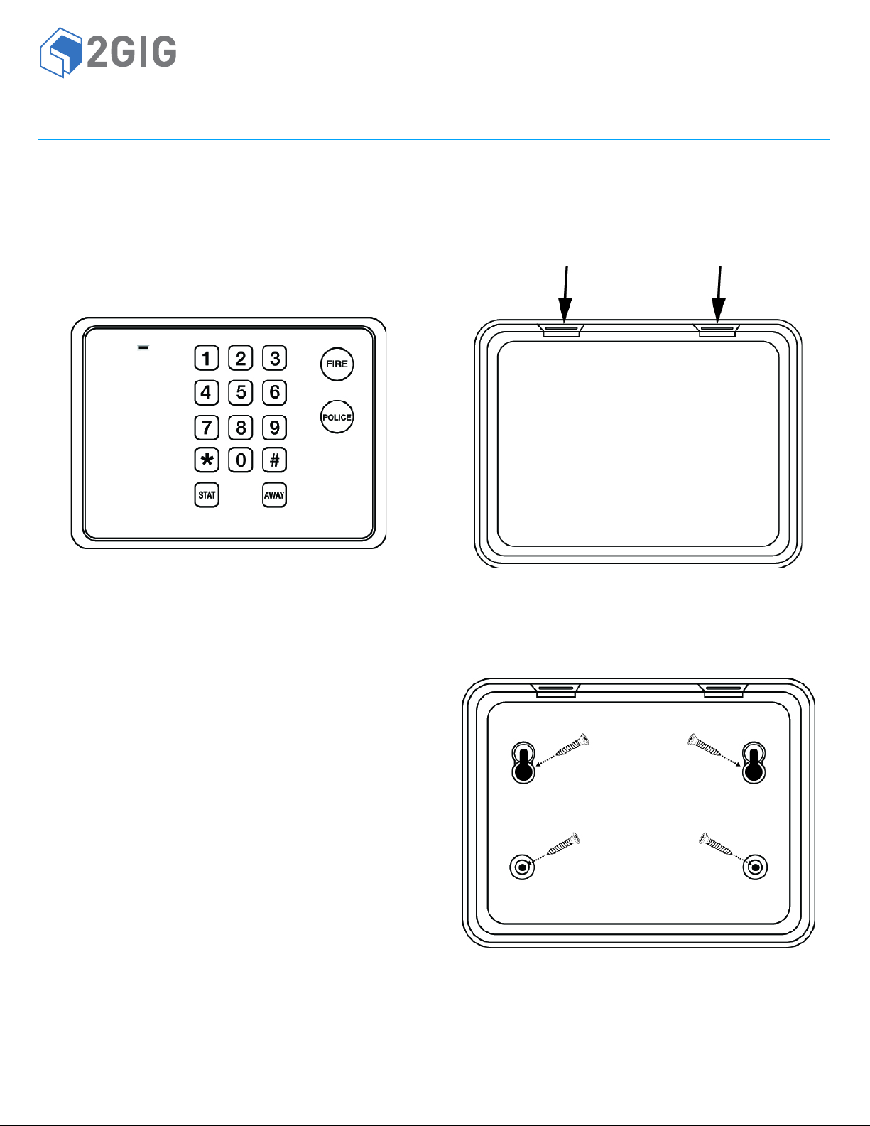
5Reattachthemountingplatetotheunitbyaligningthebottomof
theplatewiththeunitandtiltingtheunitupuntilitsnapsinto
place.
Installing and Replacing the Batteries
Toinstallandreplacethebatteries:
1Pressthehingedtabsontopofthekeypadtoseparatethe
mountingplatefromtheunit.SeeFigure2onpage1.
2Placeasmallflatheadscrewdriverintheslotbetweenthemetal
clipandthebattery.SeeFigure4above.
3Twistthescrewdriverslightlywhileholdingtheblackplasticedges
holdingthebattery.SeeFigure4above.
4Insertthereplacementbatteriesinthecompartment.Theplus(+)
signofbothbatteriesshouldbefacingupandtheminus(‐)side
facingdown.
5Ensurethattheprogrammingsettingsarecorrect.Fordetails,see
“Wireless(RF)KeypadProgramming”intheControlPanel’s
Installation&ProgrammingGuide.
WARNING: Failuretofollowthesewarningsandinstructionscan
leadtoheatgeneration,rupture,leakage,explosion,fire,or
otherinjury,ordamage.Donotinsertthebatteryintothe
compartmentinthewrongdirection.Alwaysreplacethe
batterywiththesameorequivalenttype(seeSpecifications
onpage2).Neverrechargeordisassemblethebattery.Never
placethebatteryinfireorwater.Alwayskeepbatteriesaway
fromsmallchildren.Ifbatteriesareswallowed,promptlysee
adoctor.
CALIFORNIA ONLY: ThisproductcontainsLithiumManganese
DioxideBatteries.PerchlorateMaterial‐specialhandlingmay
apply.http://www.dtsc.ca.gov/hazardouswaste/perchlorate/
6TesttheunitforgoodRFcommunications.SeeSpecifications.
SPECIFICATIONS
WirelessSignalRange 350ft(106.7m),openair,withWireless
ControlPanel
CodeOutputs KeyPress0‐9;*;#;Stay;Away;Fire;Police;
Supervisory;LowBattery
TransmitterFrequency 345.00MHz(crystalcontrolled)
UniqueIDCodes Overone(1)milliondifferentcode
combinations
SupervisoryInterval 70minutes
Dimensions(LxWxH) 5.73x4.25x1.00in(14.6x0.8x2.5cm)
Weight(includingbattery) 7.75oz(219.7g)
HousingMaterial ABSPlastic
Color WhitewithSilverTrim
OperatingTem p e rature 32°to120°F(0°to49°C)
RelativeHumidity 5‐90%Non‐Condensing
Battery(installed) Two(2)CR20323VorequivalentLithium
coinbatteries
Certification Anatel,ETL,FCC,IC,IFETEL,andNOM
REGULATORY INFORMATION
FCC Notice
ThisdevicecomplieswithPart15oftheFCC'sRules.Operationis
subjecttothefollowingtwoconditions:
1Thisdevicemaynotcauseharmfulinterference,and
2Thisdevicemustacceptanyinterferencereceived,including
interferencethatmaycauseundesiredoperation.
Thisequipmenthasbeentestedandfoundtocomplywiththelimits
foraClassBdigitaldevice,pursuanttoPart15oftheFCCRules.These
limitsaredesignedtoprovidereasonableprotectionagainstharmful
interferenceinaresidentialinstallation.
Thisequipmentgenerates,usesandcanradiateradiofrequency
energyand,ifnotinstalledandusedinaccordancewiththe
instructions,maycauseharmfulinterferencetoradio
communications.However,thereisnoguaranteethatinterference
willnotoccurinaparticularinstallation.Ifthisequipmentdoescause
harmfulinterferencetoradioortelevisionreception,whichcanbe
determinedbyturningtheequipmentoffandon,theuseris
encouragedtotrytocorrecttheinterferencebyoneormoreofthe
followingmeasures:
• Reorientorrelocatethereceivingantenna.
•Increasetheseparationbetweentheequipmentandreceiver.
• Connecttheequipmentintoanoutletonacircuitdifferent
fromthattowhichthereceiverisconnected.
•Consultthedealeroranexperiencedradio/TVtechnicianfor
help.
ThisproductcomplieswithFCCradiationexposurelimitsforan
uncontrolledenvironment.Avoidoperatingthisproductatadistance
lessthan20cmfromtheuser.
CAUTION: Anychangesormodificationsnotexpresslyapproved
bythepartyresponsibleforcompliancecouldvoidtheuser's
authoritytooperatethisequipment.
AMetalClips
BHingedTabs

Copyright © 2015 Nortek Security & Control LLC 3
Industry Canada (IC) Compliance
ThisdevicecomplieswithIndustryCanadalicense‐exemptRSS
standard(s).Operationissubjecttothefollowingtwoconditions:(1)
thisdevicemaynotcauseinterference,and(2)thisdevicemustaccept
anyinterference,includinginterferencethatmaycauseundesired
operationofthedevice.
Repairstocertifiedequipmentshouldbemadebyanauthorized
Canadianmaintenancefacilitydesignatedbythesupplier.Anyrepairs
oralterationsmadebytheusertothisequipment,orequipment
malfunctions,maygivethetelecommunicationscompanycauseto
requesttheusertodisconnecttheequipment.
Usersshouldensurefortheirownprotectionthattheelectrical
groundconnectionsofthepowerutility,telephonelinesandinternal
metallicwaterpipesystem,ifpresent,areconnectedtogether.This
precautionmaybeparticularlyimportantinruralareas.
Usersshouldnotattempttomakesuchconnectionsthemselves,but
shouldcontacttheappropriateelectricinspectionauthority,or
electrician,asappropriate.
LIMITED WARRANTY
ThisNortekSecurity&ControlLLCproductiswarrantedagainst
defectsinmaterialandworkmanshipfortwo(2)years.Thiswarranty
extendsonlytowholesalecustomerswhobuydirectfromNortek
Security&ControlLLCorthroughNortekSecurity&ControlLLC’s
normaldistributionchannels.NortekSecurity&ControlLLCdoesnot
warrantthisproducttoconsumers.Consumersshouldinquirefrom
theirsellingdealerastothenatureofthedealer’swarranty,ifany.
TherearenoobligationsorliabilitiesonthepartofNortekSecurity&
ControlLLCforconsequentialdamagesarisingoutoforinconnection
withuseorperformanceofthisproductorotherindirectdamages
withrespecttolossofproperty,revenue,orprofit,orcostofremoval,
installation,orreinstallation.Allimpliedwarrantiesforfunctionality,
arevalidonlyuntilthewarrantyexpires.ThisNortekSecurity&
ControlLLCWarrantyisinlieuofallotherwarrantiesexpressedor
implied.
2GIG
1950CaminoVidaRoble,Suite150
Carlsbad,CA92008USA
FortechnicalsupportintheUSAandCanada:
Dial:855‐2GIG‐TECH(855‐244‐4832)
Email:2gigtechsupport@nortek.com
Visitwebsitefortechnicalsupporthoursofoperation
FortechnicalsupportoutsideoftheUSAandCanada:
Contactyourregionaldistributor
Visitdealer.2gig.comforalistofdistributorsinyourregion
10004966Rev.A
ANortekCompany
Other Nortek Security & Control Keypad manuals
Popular Keypad manuals by other brands

Tyco Security Products
Tyco Security Products Visonic KP-160 PG2 user guide

Clicker
Clicker K3 user manual

Crestron
Crestron INET-CBDEX-E Installation & operation guide

Storm Interface
Storm Interface Nav-Pad Technical manual

RSI VIDEO TECHNOLOGIES
RSI VIDEO TECHNOLOGIES videofied CMA200 Installation datasheet

General Lock
General Lock L100 Series installation instructions