manuals.online logo
Brands
  1. Home
  2. •
  3. Brands
  4. •
  5. Nortek
  6. •
  7. Heater
  8. •
  9. Nortek REZNOR GUARDIAN GB Series User manual

Nortek REZNOR GUARDIAN GB Series User manual

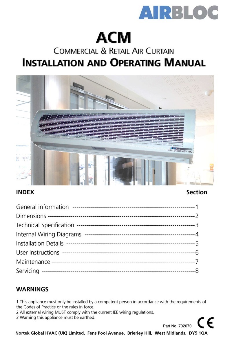
MANUAL PART NO. D301214 ISS B
INSTALLATION MANUAL
GUARDIAN GB, GR AND GS
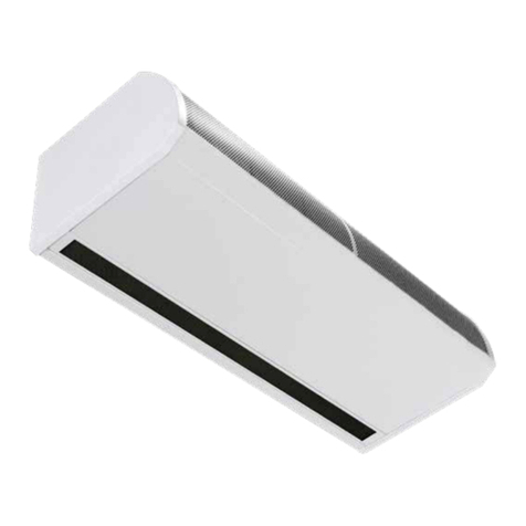
COMMERCIAL AIR CURTAIN RANGE
BS EN ISO 12100:2010 Safety of machinery.
BS EN 60204-1:2018 Safety of machinery. Electrical equipment of machines.
BS EN 55014-1:2017 Electromagnetic compatibility.
BS EN 60335-2-30:2009+A11:2012 Safety. Requirements for room heaters to the following
European CE directives- 2006/95/EC - low voltage; 2014/30/EU - electromagnetic compatibility
Please read this document carefully before commencing installation, commissioning and/or servicing.
Leave it with the end user/site agent to be placed in their premises technical file after installation.
WARNING
Improper installation, adjustment, alteration, service or maintenance can cause property damage, injury or death.
All work must be carried out by appropriately qualified persons.
The manufacturer does not take any responsibility in the event of non-observance of the regulations concerning the connection of the apparatus causing a
dangerous operation possibly resulting in damage to the apparatus and/or environment in which the unit is installed.
AMBIENT, LPHW AND ELECTRIC HEATED
General Information (G)
Guardian air curtain range .................................4
General product information...............................4
Health and safety ...............................................4
Requirements .....................................................5
Clearance distances ............................................5
Electrical ............................................................5
SmartElec controller ............................................5
Important notice to installers ..............................5
Using this manual ..............................................5
Technical Data (TD)
Technical data .....................................................6
Fuses .................................................................7
Dimensions. GS Surface mounted models ...........8
Clearance distances ............................................8
Dimensions. GR Recessed models........................9
Clearance distances ............................................9
Dimensions. GB Bulkhead mounted models ......10
Clearance distances ..........................................10
Program panel dimensions................................11
Component layout ...........................................12
LPHW coil technical data ..................................37
Installation (I)
Installation .......................................................13
Mounting .........................................................13
Electrical supply. ...............................................13
Installation process ...........................................14
Suspending on threaded rods ..........................15
Wall mounting bracket ....................................15
Installation details - LPHW Only.........................16
Program panel ..................................................17
Standard and high capacity fan & heat settings 18
Fan speed setting .............................................18
Ambient and LPHW model................................18
Wiring diagrams. ..............................................19
Installer wiring Ambient single phase ...............19
Protection .........................................................19
Installer wiring Electric heated three phase only 20
Protection .........................................................20
Installer wiring LPHW single phase ....................21
Protection .........................................................21
Optional wiring.................................................22
Controller (C)
Networking.......................................................22
Air curtain addressing .......................................22
Power-up manual reset .....................................23
Ambient & LPHW models..................................23
Standard settings .........................................23
Engineers settings........................................24
Door link settings.........................................24
Link-group interlock.....................................24
All controllers...............................................24
External temperature ...................................24
External temperature offset..........................24
Temperature limits .......................................25
Air return & pipe cold sensors ......................25
Electric Heated models......................................25
Keypad display.............................................25
Normal mode displays..................................25
Normal operation.........................................25
OFF mode....................................................25
Settings mode..............................................25
Settings display............................................26
Setup configurations....................................26
Set fan speed...............................................26
Set temperature...........................................26
Networked air curtains.................................26
Engineer settings .........................................26
Door link settings .......................................26
Link-group lockout.......................................27
External temperature ...................................27
External temperature offset..........................28
Temperature limits ......................................28
keypad sequences.............................................28
Modbus protocol ..............................................29
Modbus address ...............................................29
Modbus function codes supported....................29
Maintenance & servicing (MS)
Maintenance and servicing................................31
Inlet foam filter replacement GS........................31
Inlet foam filter replacement GR ......................32
Honeycomb outlet replacement .......................32
Fault Finding (FF)
Fault finding. ....................................................33
General.............................................................33
Electrically heated units only. ............................33
Program panel. .................................................33
SmartElec fault codes........................................34
Spare Parts (SP)
Spare parts. ......................................................35
General.............................................................35
Parts Replacement (PR)
Parts replacement. ............................................36
Control panel ..................................................36
Heating element ..............................................36
Fan deck...........................................................36
Contents
Page No 4 Reznor, Guardian GB GR and GS, Installation Manual, EN 2020-06, D30121 Iss B
GGuardian air curtain range
General product information
Models
• GS Surface mounted model
• GR Recessed mounted model
• GB Bulkhead mounted model
Three sizes
• 1000mm
• 1500mm
• 2000mm
Three variations
• Ambient (not heated)
• Electrically heated
• LPHW (low pressure hot water)
The new design allows for quick and easy access to
the control panel and the installers terminal block,
the GS range has two access panels on the 1000,
three on the 1500 and four on the 2000. The GR has
hinged access panels which can be removed with
ease
Electric heated versions require a three phase (415v)
electrical supply, whilst all other versions need a
single phase (230v) supply
All units have fans capable of providing standard &
high capacity air duties. Electric & LPHW also offer
standard & high capacity heating outputs.
Units are designed for versatile installation, options
of wall mounted, recessed within a false ceiling,
fitted in a bulkhead, or on drop rods in front of glass
fronted entrances.
A wall mounting bracket is available as an optional
extra. Units can be mounted adjacent to each
other to cover the full door opening across wider
entrances.
All models are supplied with a program panel and
10m length of RJ45 communication cable.
The program panel allows the user to control either
a single air curtain, or a network of up to 16 air
curtains.
Easy programming the end users simply select
whether they require the heat on or off (not ambient
models), the required fan setting (1,2 or 3 speed),
and the outlet temperature setting
Options for BMS compatible via Modbus
communication can be linked to optional external
thermostat for proportional control in various set
temperatures
Health and safety
Before installing, carefully read the instructions and
follow the processes explained by the manufacturer
Check that the temperature ranges given and
those of the location match. The appliance must be
powered with a voltage corresponding to the value
shown on the rating plate.
Ensure that anchoring points are suitable for the
weight and loading of the product and if required,
add suitable reinforcement to the anchoring points
area.
Installing, programming, commissioning, and
maintenance of these products must only be carried
out by suitably qualified and trained technicians and
in full compliance of all applicable regulations and
current best practices.
Due consideration should be taken for workplace
safety, risk assessments and waste disposal.
Any modification of the product may be hazardous
and the manufacturer is not liable for any damage or
injury caused by improper use
Reznor, Guardian GB GR and GS, Installation Manual, EN 2020-06, D30121 Iss B Page No 5
G
Requirements
Clearance distances
For installation and maintenance clearances, please
see the information on page 8 for the GS models,
page 9 for the GR models and page 10 for the GB
models.
Electrical
For full electrical loadings, please refer to the
technical data section on page 6 of this manual.
It is recommended that the electrical supply to the
base unit in the air curtain is via an appropriate
switched isolator, fitted in accordance with the
regulations in force in the country of use and must
be via a fused isolator having a contact separation of
greater than 3mm in all poles.
For safety reasons a good earth
connection must ALWAYS be made to
the heater and control box.
SmartElec controller
Electric heated models have a supply requirement of
415V 3 phase, neutral and earth. Maximum cable
inlet size is 10mm².
Program panel is wired to the control base unit via a
RJ45 pre-wired cable.
Networked air curtain interconnects via a RJ45 pre-
wired cable
Important notice to installers
Before installation, check the local
distribution conditions, supply
voltage and nature of
water and pressure (LPHW), are
compatible.
Installation, assembly, commissioning,
service and maintenance procedures
must be carried out only by suitable
competent qualified persons.
Unauthorised modifications to the
appliance, or departure from the
manufacturer’s guidance on
intended use, or installation
contrary to the manufacturer’s
recommendations may constitute
a hazard.
Note
To ignore the warning and caution notices, and
to ignore the advice from the manufacturer on
installation, commissioning, servicing, or use,
will jeopardise any applicable warranty, such
a situation could also compromise the safe and
efficient running of the appliance itself, and
thereby constitute a hazard.
Using this manual
Contained within the text of the manual, the
symbols for ‘Caution’ and ‘Warning’ these are used
to highlight certain points.
Caution is used when failure to follow
or implement the instruction(s) can
lead to premature failure or damage
to the unit or its component parts.
Warning is used when failure to heed
or implement the instruction(s) can
lead to not only component damage,
but also to a hazardous situation
being created where there is a risk of
personal injury.
Page No 6 Reznor, Guardian GB GR and GS, Installation Manual, EN 2020-06, D30121 Iss B
TD
Technical data
Data Fan speed Unit 1000 1500 2000
All models
Maximum door width L, M, H m 1.0 1.5 2.0
Maximum mounting height standard capacity L, M m 3.0
Maximum mounting height high capacity H m 4.0
Maximum air volume
L m3/h 1150 1730 2300
M m3/h 1440 2270 2880
H m3/h 1800 2700 3600
Maximum velocity at 0 metre
L m/s 6.4
M m/s 8 8.4 8
H m/s 10 10.1 10
Maximum velocity at 1 metre H m/s 5.6 5.2 5.4
Maximum velocity at 2 metre H m/s 3.8 3.5 3.7
Maximum velocity at 3 metre H m/s 2.8 2.5 2.8
Motor power L, M, H W 365 530 730
Noise level @ 3m free field
L dB(A) 52
M dB(A) 55
H dB(A) 59
Program panel control wiring RJ45 (pre-wired cable required)
Cable terminal size 1.5mm^2 MAX
Electric Heated Models
Electrical supply L, M, H 415V 3 phase 50Hz
Heating capacity - standard L, M, H kW 9 12 18
Heating capacity - high L, M, H kW 12 18 24
Total electrical load -per phase standard
L A 13.7 18.3 27.4
M A 13.8 18.4 27.7
H A 13.8 18.5 27.8
Heat current per phase standard
L A 12.53 16.78 25.08
M A 12.51 16.66 25.05
H A 12.44 16.53 25.00
Total electrical load -per phase high
L A 17.9 26.6 35.7
M A 18.0 26.8 36.0
H A 18.0 27.0 36.2
Heat current per phase high
L A 16.73 25.08 33.38
M A 16.71 25.06 33.35
H A 16.64 25.03 33.40
Temperature rise - Standard
(No Jumpers 9/12/18kW)
L °C 28 27 27
M °C 23 24 23
H °C 18 17 19
Temperature rise - High
(Jumpers in 12/18/24kW)
L °C 34 33 33
M °C 29 28 29
H °C 24 22 24
Weight L, M, H kg 34.5 52 64.5
External fuse size (D type MCB) H A 20 32 40
Reznor, Guardian GB GR and GS, Installation Manual, EN 2020-06, D30121 Iss B Page No 7
TD
Ambient Models
Electrical supply L, M, H 230V single phase 50Hz
Total electrical load
L A 1.17 1.52 2.32
M A 1.29 1.74 2.65
H A 1.36 1.97 2.8
Weight L, M, H kg 32 48.5 60
External fuse size (D type MCB) H A 6
LPHW Heated Models
Electrical supply L, M, H 230V single phase 50Hz
Maximum heating capacity standard L, M, H kW 9 12 18
Maximum heating capacity high L, M, H kW 12 18 24
Total electrical load
L A 1.17 1.52 2.32
M A 1.29 1.74 2.65
H A 1.36 1.97 2.8
Temperature Rise - Standard
(9/12/18kW)
L °C 28 27 27
M °C 23 24 23
H °C 18 17 19
Temperature Rise - High
(12/18/24kW)
L °C 34 33 33
M °C 29 28 29
H °C 24 22 24
Weight (incl water) L, M, H kg 38.5 58 72
External fuse size (D type MCB) H A 6
Table 1 Technical data
Standard Capacity is the factory default. High Capacity is achieved by using the Jumpers provided in the
installation pack, (see parts table on page 35) and additional information on standard and high capacity
fan and heat settings on page 18, Standard = default heating capacity.
High = jumpers fitted in terminals 1a to 6a selectable by installer
LPHW kW ratings based upon a flow & return water temperature of 82/72°C
Fuses
All of the circuit boards in the Guardian air curtain range have a control fuse T1H which covers the fans. The
electric model with the SmartElec board has two additional large fuses to protect the heating elements. F2
and F3
Figure 1 Fuse location electric model board shown
Page No 8 Reznor, Guardian GB GR and GS, Installation Manual, EN 2020-06, D30121 Iss B
TD
Dimensions. GS Surface mounted models
Clearance distances
It is recommended that a minimum clearance of 100mm is allowed around the top and front of the unit.
The clearance allows for cable entry and prevents combustible surfaces overheating.
The minimum mounting height (floor to grille outlet) is 1.8m. The recommended maximum mounting height
is 3m for standard fan setting & 4m for high
Figure 2.2 GS Bottom view
Figure 2.1 GS Front view
Figure 2 GS Top view
Reference GS 1000 GS 1500 GS 2000
1 440
2 1094 1620 2148
3 227
4 70
5 132 130 132
6 830 1360 1884
7 306
8 440
9 >100
Figure 2.3 GS Side view
Table 2 GS dimensions
Reznor, Guardian GB GR and GS, Installation Manual, EN 2020-06, D30121 Iss B Page No 9
TD
Table 2 GS dimensions
Reference GR 1000 GR 1500 GR 2000
1 1125 1650 2177
2 457
3 1060 1584 2111
4 70
5 114 112 114
6 830 1360 1884
7 298
8 438
9 273
Clearance distances
It is recommended that a minimum clearance of 100mm is allowed around the case. The clearance allows
for cable entry and prevents combustible surfaces overheating.
The minimum mounting height (floor to grille outlet) is 1.8m. The recommended maximum mounting height
is 3m for standard fan setting & 4m for high.
Figure 3.2 GR Bottom view
Figure 3.1 GR Front view
Figure 3 GR Top view
Figure 3.3 GR Side view
Dimensions. GR Recessed models
Table 3 GR dimensions
Page No 10 Reznor, Guardian GB GR and GS, Installation Manual, EN 2020-06, D30121 Iss B
TD
Dimensions. GB Bulkhead mounted models
Figure 4 GB Top view
Figure 4.1 GB Front view
Figure 4.2 GB Bottom view
Reference GB 1000 GB 1500 GB 2000
1 70
2 114 112 114
3 830 1360 1884
4 226
5 1060 1584 2111
6 448
7 1125 1650 2177
8 436
9 300
10 427-487
Figure 4.3 GB Side view
Table 4 GB Dimensions
Clearance distances
It is recommended that a minimum clearance of 100mm is allowed around the case. The clearance allows
for cable entry and prevents combustible surfaces overheating.
The minimum mounting height (floor to grille outlet) is 1.8m. The recommended maximum mounting height
is 3m for standard fan setting & 4m for high.
Reznor, Guardian GB GR and GS, Installation Manual, EN 2020-06, D30121 Iss B Page No 11
TD
Program panel dimensions
The program panel is supplied with an industry standard plastic double surface mounted socket box.
Alternatively, the program panel can be flush mounted using a customer supplied metal flush conduit box as
shown in Figure 5.2
Figure 5 Surface mount box
Figure 5.2 Surface mounting back box dimensions
Figure 5.1 Flush mounting using metal conduit
box (by others)
Page No 12 Reznor, Guardian GB GR and GS, Installation Manual, EN 2020-06, D30121 Iss B
TD
Component layout
Figure 6 Component layout GS
Location Component
1 Control panel
2 Installer terminal block
3 Fan
4 Fan motor
5 Fan deck
6 Transformer (1500 only)
7 Heating element
Table 5 GS & GR components
Figure 7 Component layout GR
Reznor, Guardian GB GR and GS, Installation Manual, EN 2020-06, D30121 Iss B Page No 13
I
Installation
Mounting
Guardian GS,GR and GB air curtain units are
designed to be installed horizontally directly over the
door opening on the inside of the building, against a
wall or ceiling.
Care must be taken to allow complete
free air movement into the inlet
grilles of the unit to ensure the
correct working operation of the
air curtain. The honeycomb outlet
should be as close to the top of the
door as possible and can be angled
towards the door from 0° to -5°.
Ensure to cover the entire door
width. See figure 8
Units can be mounted adjacent to each other to
cover the full door opening across wider entrances.
The GS units are designed for surface
mounting and should not be placed
into a ceiling void, due to possible
obstruction of airflow and difficulty
in routine cleaning and maintenance.
Use the GR for these types of
applications
It is the sole responsibility of the
installer to ensure that the points of
attachment to the building are
sound.
Verification with the consultant/
architect or owner of the building is
recommended to ensure that a sound,
stable installation can be achieved.
Figure 8 Honeycomb outlet position near to the
door adjustable angle of 0 to -5°
Electrical supply.
Electrically heated units require a connection to 3
phase 415V power supply only.
Ambient and LPHW models require a connection to
single phase 230/240V supply only.
Electrically heated models consume 9kW, 12kW,
18kW & 24kW at 415 Volts when switched to the
full heat position depending on the model and
capacity setting.
The appliance shall be connected to the supply via
an appropriate a switched fused isolator, having
a contact separation of greater than 3mm. See
technical data for fuse rating on page 6
Once the covers have been removed, the installation
engineers terminal block is located to the right
hand side of the unit. This terminal block is used
for the connection of the mains supply and
additional controls, for example door switch. Wire in
accordance to the appropriate unit diagrams in the
wiring section, starting on page 19
For safety reasons, a sound earth
connection must always be made to
the unit before it is put in to use. The
unit should be wired in
accordance with IEE Regulations for
the Electrical Equipment of
Buildings.
The program panel is connected to
the control panel (base unit) via a
pre-wired RJ45 cable maximum length
of 100m. (10m supplied as standard).
It is recommended that this cable is
run separately within its own
trunking to avoid external
interference.
Page No 14 Reznor, Guardian GB GR and GS, Installation Manual, EN 2020-06, D30121 Iss B
I
Installation process
1. Remove all packaging and covers
Note All outer metal surfaces are covered by a
protective plastic film, which must be removed
before final fixing and operation of the unit.
2. GS units, Loosen (DO NOT REMOVE) the screws
in the top of each front inlet cover [1] (see figure
9.1and 10 dog bone slot) then slide the left
cover to the left [2] which will allow the cover to
slide under the end cap. This will allow the next
cover to be pushed to the left [3] (see figure 9.1)
allowing it to be released from the screw slot [4]
by pulling forward and lifted upwards out of the
lower grove in the case.
3. The first cover can then be pushed to the right
to release it from the screw slot, (see figure
10) then pull forward and lift upwards to be
removed. For additional covers fitted on the
1500 or 2000 units loosen the fixing screws and
remove as with the previous covers.
Figure 9 GS cover fixing point
Figure 9.1 GS cover fixing point
Figure 9.2 GS cover fixing point
Figure 10 Dog bone screw fixing slot
4. On the GS units the lower cover can be removed
by removing the two screws at the top of this
cover and then pulled out of the tabs from the
main case
Figure 11 GS lower access panel
1. The GR has two captive screws in each panel,
loosen these and hinge the panel down.
2. The panel can be removed completely by
releasing the bolt hinges on either side of the
panel (see figure 13).
Figure 12 GR cover fixing point
Figure 13 GR bolt hinge
1
1
1
1
2
3
4
4
Reznor, Guardian GB GR and GS, Installation Manual, EN 2020-06, D30121 Iss B Page No 15
I
Suspending on threaded rods
1. The product is installed using 4 x M10 threaded
rods fitted into the fixing points in the top of
casing.
2. The threaded rods must completely pass through
the fixing points in the case without being too
long to cause damage to products inside the
case.
3. Ensure that the secure mounting point in the
ceiling is capable of supporting the weight of the
unit.
4. Lift the unit (using lifting equipment) onto
threaded rods ceiling fixing point.
Figure 14 Suspending from threaded rods
5. Level the unit and tighten the fixing points.
Carryout a final check to ensure the unit remains
level
6. Holes are provided in the casing for cable
entry. Choose the appropriate hole to suit the
installation. Note the terminal connection block
is located to the right of the unit.
7. Install the cable into the case using a suitable
cable gland for size of cable
8. Two RJ45 ports are located in the case to
connect the program panel and any other air
curtains to be controlled
9. Adjust outlet to required angle to give desired
performance and tighten outlet grille.
10. Fit the Program panel and commission the unit
Wall mounting bracket
Figure 15 Wall mounting bracket
Figure 15.1 Side view
Figure 15.1 shows the overall dimensions of the wall
bracket assembly.
Figure 15.2 Front view
Figure 15.2 shows the dimensions of the bracket
that is to be fixed to the wall, along with fixing
positions. Please ensure that adequate fixings and
wall structure are present to support the unit weight.
355
25
47
300
82
30
150120
Ø
11
Ø
11
Page No 16 Reznor, Guardian GB GR and GS, Installation Manual, EN 2020-06, D30121 Iss B
I
Figure 15.3 Mounting bracket top view
Figure 15.3 shows the dimensions of the bracket
section that is to be fixed to the unit using 4 x M10
x 30mm 8.8 set screws, 4 x shake prove washers and
4 x flat washers. Use the four fixing points supplied
in the casing
1. Using the details supplied with the bracket
position the bracket against the wall at the
desired mounting height and mark through the
holes
2. Drill the wall then fix the brackets in position. Lift
the chassis (using lifting gear if necessary) onto
drop rods in the bracket
3. Ensure the unit is level and then tighten the
fixing points with a final check to ensure the unit
is level
4. Follow the instructions 6 to 10 of the drop rod
mounting instructions grille.
Figure 16 Mounting bracket option
Figure 16.1 Mounting bracket fitted to GB unit
Installation details - LPHW Only
Installation of the LPHW unit is as described earlier.
Once situated, access to the heating coil and
controller base unit is via removal of the case front.
The LPHW copper tubing connections are 22mm
outside diameter. Ensure correct water seal fittings
are used. It is recommend to use a suitable water
mains isolation valve to ease any maintenance.
The unit is handed for right hand pipe connection.
Figure 17 Typical schematic of a 3-port valve
system.
Reznor, Guardian GB GR and GS, Installation Manual, EN 2020-06, D30121 Iss B Page No 17
I
Program panel
The program panel can be installed using the
standard double surface box supplied with the
program panel or recessed using a suitable flush
mounted double conduit box. see “Figure 5.2
Surface mounting back box dimensions” on page
11 for details
Figure 18 Program panel
The program panel can be connected up to a
maximum of 16 air curtains in one network.
For mains wiring refer to the wiring diagram relating
to the model being used see “Wiring diagrams.” on
pages 19 to 21
The program panel is connected to the base unit in
the air curtain via pre-wired RJ45 cable/plugs. These
cables are available in 2, 10, 20, 30, 50 and 100m
lengths. It is recommended that this control cable
is run separately within its own trunking to avoid
external interference.
Maximum cable run in any network
must not exceed 100m in total
including program panel cable.
Note: All air curtains connected within the
network system will operate under the settings
of the single program panel.
Any air curtain within the network can be
connected with and respond to the following
optional circuits:
• External switch (ie BMS enable) where required,
to be volt free and wired in PARALLEL via
normally open contacts to each terminal pair
‘TIMER’. (Contacts closed to enable). Only air
curtain(s) wired this way will respond to the
enable signal.
• Door switches where required, to be volt free
and wired to INDIVIDUAL base units via normally
closed contacts to each terminal pair ‘DOOR’.
(Contacts open to enable door mode). Only air
curtain(s) wired this way will respond to the door
mode.
• An external sensor, where required, can be wired
to INDIVIDUAL base units to each terminal pair
‘EXT’. Only air curtain(s) wired this way will
respond to the sensor setting.
Page No 18 Reznor, Guardian GB GR and GS, Installation Manual, EN 2020-06, D30121 Iss B
I
Standard and high capacity fan and heat settings
All units are supplied as standard capacity
All units have fans capable of providing standard &
high capacity air duties (speeds Medium and High)
which are controlled via the program panel supplied
with every unit.
Electrically heated units provide standard & high
capacity heating outputs.
These settings can be quickly changed from standard
to high capacity on site by the installation engineer.
Fan speed setting
On the Program panel during normal operation
mode the display is dimmed.
Pressing the SELECT button, will put the panel
into active mode. If no button is pressed for several
seconds the display reverts to normal mode.
Once the display becomes illuminated press the
SELECT button once.
Display shows the fan speed. (default is F0)
Press +to increase fan speed.
Press – to decrease fan speed.
Three speeds and an ‘off’ setting are available:
[0 F1] = Speed 1 (Low)
[0 F2] = Speed 2 (Medium-Standard)
[0 F3] = Speed 3 (High)
[0 F0] = Fan off
Ensure the supply cables are adequate
for the higher loading with the high
capacity settings of the fans. See
technical data on page 6
Ambient and LPHW model
The Ambient models have no heat elements, and the
LPHW models has a coil which the capacity cannot
be controlled by the internal circuit board, therefore
only the fan capacity can be changed to suit site
requirements.
This is achieved by altering the fan speed setting in
the program display.
Note: The LPHW heat output can be controlled
via a 3rd party thermostat and valve connected
to the heat network control system.
Electrically heated model
On the electrically heated models the fan capacity
can be adjusted in the same as the ambient by
setting the fan speed to F1, F2 or F3
The heat capacity can be changed by fitting the
jumpers E1, E2 and E3 in to the installers terminal
block 1a to 6a see wiring diagram on page 20
Figure 19 Heat capacity jumpers factory setting
(no jumpers fitted)
Figure 19.1 Heat capacity jumpers HIGH
capacity (jumpers fitted)
Figure 19.2 Heat capacity jumper pack part
number 1026901
0 F1
0 F2
0 F3
0 F0
Reznor, Guardian GB GR and GS, Installation Manual, EN 2020-06, D30121 Iss B Page No 19
I
Wiring diagrams.
NOTE External switch inputs (e.g. Timer) to be volt free and wired via normally open contacts to
terminal pair marked e.g. ‘timer’ (contacts closed to enable). Remove relevant factory fitted jumper
for any optional input.
Installer wiring - Ambient models, single phase
N
L
E
CONTROL BOARD
(located in air curtain)
CHASSIS
EARTH
NLE
3
4
5
6
1 2 3N
FAN
1 2 3 4
ON
Comms
RS485
EXT
DOOR
PIPE COLD
AIR RETURN
STAT
TIMER
FILTER
FAN 0-10v
FAIL O/P
VALVE 0-10v
AIR OUTLET
Ext Timer
(BMS)
Door Switch
Ext Temp
Sensor
J1 J2
Programmer
Keypad
SELECT
RJ45 Cable
230v 50Hz
MAINS SUPPLY
Factory Connections
Installer Wiring
900698 Guardian Series Ambient - Installer Connections
1
2
Violet
Yellow
Red
Green / Yellow
Brown
Blue
Figure 20 Wiring diagram ambient
Terminal Description Cable
N Neutral
1.5mm²
L1 Phase 1 (or 1 Phase
supply)
E Mains earth
Timer BMS (J1) Optional external
switch
Door (J2) Optional door contact
Ext Optional external sensor
PCB Fuses Rating (A)
F1 T1H (slow blow)
Table 6 Cable specification ambient
Protection
External circuit breaker with the appropriate
rating should be installed for the protection of the
installation.
Page No 20 Reznor, Guardian GB GR and GS, Installation Manual, EN 2020-06, D30121 Iss B
I
Installer wiring - Electric heated models, three phase only
12 3 N N
HEHEHE
L1 L2 L3
EXT
DOOR
STAT
TIMER
TEMP
FAN CHASSIS
EARTH
415v 50Hz
MAINS SUPPLY
SMARTELEC
(located in air curtain)
RJ45 Cable
Comms
RS485
Programmer
Keypad
L1L2L3NE
External Switch
(BMS)
Door Switch
External Temp
Sensor
J1 J2
Factory Connections
Installer Wiring
900697 Guardian Series Electric - Installer Connections
FAN 0-10v
FAIL O/P
1 2 3 4
ON
SELECT
5
6
1
2
3
4
5a
6a
1a
2a
3a
4a
E1 E2 E3
Connections
to Elements
Heat Capacity
Jumpers
Violet
Yellow
Red
Green / Yellow
Blue
Brown
Grey
Black
Figure 21 Wiring diagram electric heated
Terminal Description Cable
E Mains earth
10mm²
N Neutral
L1 Phase 1
L2 Phase 2
L3 Phase 3
1a to 6a Capacity jumpers see page 18
Table 7 Cable specification electric heated
Protection
There are two high speed fuses on the base
unit to protect the switching thyristors for
the heater. An external circuit breaker with
the appropriate rating should be installed
for the protection of the installation
Terminal Description Cable
Timer/BMS
(J1) Optional external switch
1.5mm²
Door (J2) Optional door contact
Ext Optional external sensor
Fail o/p Fault output (0-5v)
Fan Optional 0-10v fan output
Thermostat Internal high limit thermostat
PCB Fuses Rating (A)
F1 T1H (slow blow)
F2 & F3 400v
Table 7.1 Cable specification electric heated
continued

This manual suits for next models

11

Other Nortek Heater manuals

Nortek Reznor 85 User manual

Nortek

Nortek Reznor 85 User manual

Nortek Reznor 30 User guide

Nortek

Nortek Reznor 30 User guide

Nortek C84DA Series User manual

Nortek

Nortek C84DA Series User manual

Nortek NRV24M User manual

Nortek

Nortek NRV24M User manual

Nortek C8QA Series User manual

Nortek

Nortek C8QA Series User manual

Nortek AIRBLOC ACM900SE6 User manual

Nortek

Nortek AIRBLOC ACM900SE6 User manual

Nortek Reznor FSE Series Guide

Nortek

Nortek Reznor FSE Series Guide

Nortek REZNOR UDSBD 015-3 Guide

Nortek

Nortek REZNOR UDSBD 015-3 Guide

Nortek RENZOR GUARDIAN GB User manual

Nortek

Nortek RENZOR GUARDIAN GB User manual

Nortek H9HK Series User manual

Nortek

Nortek H9HK Series User manual

Nortek Reznor RHC DJL 8000 Guide

Nortek

Nortek Reznor RHC DJL 8000 Guide

Nortek Reznor RHC21 8000 User guide

Nortek

Nortek Reznor RHC21 8000 User guide

Nortek C6B-T User manual

Nortek

Nortek C6B-T User manual

Nortek Reznor GUARDIAN GB User manual

Nortek

Nortek Reznor GUARDIAN GB User manual

Nortek Reznor UDSA-4 User manual

Nortek

Nortek Reznor UDSA-4 User manual

Nortek C84QA Series User manual

Nortek

Nortek C84QA Series User manual

Nortek C8QV Series User manual

Nortek

Nortek C8QV Series User manual

Nortek Ambirad Vision VSX Installation guide

Nortek

Nortek Ambirad Vision VSX Installation guide

Popular Heater manuals by other brands

Frico AGS5000 Original instructions

Frico

Frico AGS5000 Original instructions

Atlas 634/0458 Assembly instructions

Atlas

Atlas 634/0458 Assembly instructions

German pool HTW-330 user manual

German pool

German pool HTW-330 user manual

Jaga STRADA HYBRID MM Installation and operation manual

Jaga

Jaga STRADA HYBRID MM Installation and operation manual

KASTOR KARHU-22 T Installation and user manual

KASTOR

KASTOR KARHU-22 T Installation and user manual

Aspira ASPIRCOMFORT CLASS 620H Installation, use and maintenance manual

Aspira

Aspira ASPIRCOMFORT CLASS 620H Installation, use and maintenance manual

VOLTOMAT HEATING FH-109313.1 instruction manual

VOLTOMAT HEATING

VOLTOMAT HEATING FH-109313.1 instruction manual

Sealey RD800 instructions

Sealey

Sealey RD800 instructions

Akai FH11AL instruction manual

Akai

Akai FH11AL instruction manual

RESTAURANTDOORS.COM AIR-PRO AP-2-36-1-S S installation instructions

RESTAURANTDOORS.COM

RESTAURANTDOORS.COM AIR-PRO AP-2-36-1-S S installation instructions

Logik L20ORW14E instruction manual

Logik

Logik L20ORW14E instruction manual

Heylo KS 85 T Translation of the original instruction manual

Heylo

Heylo KS 85 T Translation of the original instruction manual

Beper RI-085 use instructions

Beper

Beper RI-085 use instructions

Reznor UDBP Installation & operation

Reznor

Reznor UDBP Installation & operation

Thermon HELLFIRE 400 Installation, operation & maintenance instructions

Thermon

Thermon HELLFIRE 400 Installation, operation & maintenance instructions

EUROLAMP LX-1602 instructions

EUROLAMP

EUROLAMP LX-1602 instructions

Stroco 15.00 M Service instructions

Stroco

Stroco 15.00 M Service instructions

Flagro FLE-60CSA Installation and maintenance manual

Flagro

Flagro FLE-60CSA Installation and maintenance manual

manuals.online logo
manuals.online logoBrands
  • About & Mission
  • Contact us
  • Privacy Policy
  • Terms and Conditions

Copyright 2025 Manuals.Online. All Rights Reserved.